

Page 1

Parts Catalog
3600N Slicer
SLICING MACHINES
MODELS:
3600N, 3850N & 3975N
12-13-13
IMPORTANT!
TO EXPEDITE SHIPMENT OF PARTS, ALWAYS SPECIFY MODEL, REV,
PART NUMBER, AND SERIAL NUMBER OF SLICER.
GLOBE FOOD EQUIPMENT COMPANY
2215 East River Road
Dayton, Ohio 45439
Parts Department
Toll Free 1-800-745-6238 · Fax (937) 290-0585
E-Mail: globeinfo@globeslicers.com
Website: www.globeslicers.com
Not for resale
Page 2

Page 3

TABLE OF CONTENTS
Page
Slicer Base and Gear Housing 1
Base Shroud and Components 2
Knife Rim Guard 3
Knife and Knife Cover 4
Knife Sharpener 5
SS Carriage Assembly, Support and Endweight 6
Knife Motor Bearing Assembly 7
Knife Motor Components 8
Slicer Gauge Plate Assembly 9
Gauge Plate Adjustment Components 10
Carriage Slide System Components 11
Carriage Drive Components, Automatic Slicer 12
Carriage Drive Motor, Automatic Slicer 13
Automatic Base Apron and Lift Lever Assembly 14
Electrical System Components, Manual Slicer 15
Electrical System Components, Automatic Slicer 16
Carriage Fence Accessories 17
Vegetable Hopper Accessory 18
Schematic, 3600N 19
Schematic, 3850N and 3975N 20
Page 4
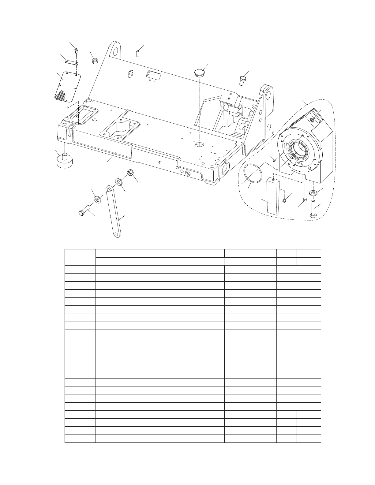
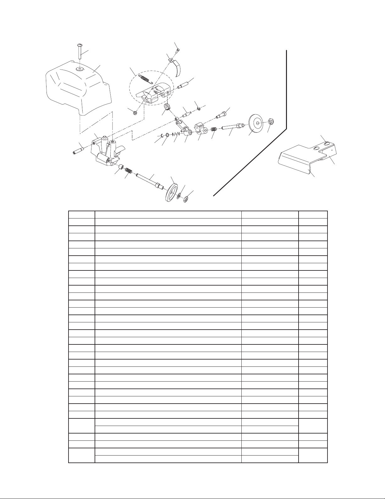
3000N SLICER BASE
5
22
6
1
16
21
20
4
3
2
23
7
8
9
10
11
13
14
16
15
12
17
18
QUANTITY
ITEM PART DESCRIPTION PART NUMBER MAN AUTO
1
2 Slicer Foot 817-S 4
3 Motor Screen 1148 1
4 Motor Screen Brace 1255 2
5 Screw, Motor Brace 1227 4
6 Split Bushing 550002 3
7 Dowel Pin 1091 2
8 Hole Plug 1208 1
9 Screw, Gauge Plate Slide Rod 975-1 1
10 Gear Housing Assembly 070051 1
*11 Vent Plug (Included with Gear Housing) - 1
12 Drain Plug 890082 1
*13 Set Screw 700-3 1
*14 O-Ring 840001 1
*15 Oil Drain Chute 520100 1
*16 Drain Chute Mounting Screw 810305 1
17 Flat Washer 763-4A 4
18 Hex Bolt 369-1 4
*19 Gearbox Oil, 6.5 oz. Bottle (Not shown) 920000 1
20 Cleaning Brace 873-CB 1 -
21 Bolt, Hex Head 477 1 -
22 Flat Washer 763-4A 2 -
23 Nut, Nylon Insert 873-CB-1 1 -
*Used only on Oil Bath & Serrated Knife Units.
Base, Manual 1385 1 Base, Automatic 460040 - 1
1
Page 5
7
2
Close The Slicer Table After Each Use
Turn Off And Unplug Before Cleaning
Or Servicing
WARNING
SHARP
KNIFE
BLADE
TO AVOID SERIOUS PERSONAL INJURY
Read Owner’s
Manual First
Do Not Use
Without
Training
Keep
Hands
Away
From
Knife And
Moving
Parts
Do Not Use
Your Hand
When Slicing, Use
The End Weight
Thoroughly Clean And Sanitize
Entire Unit
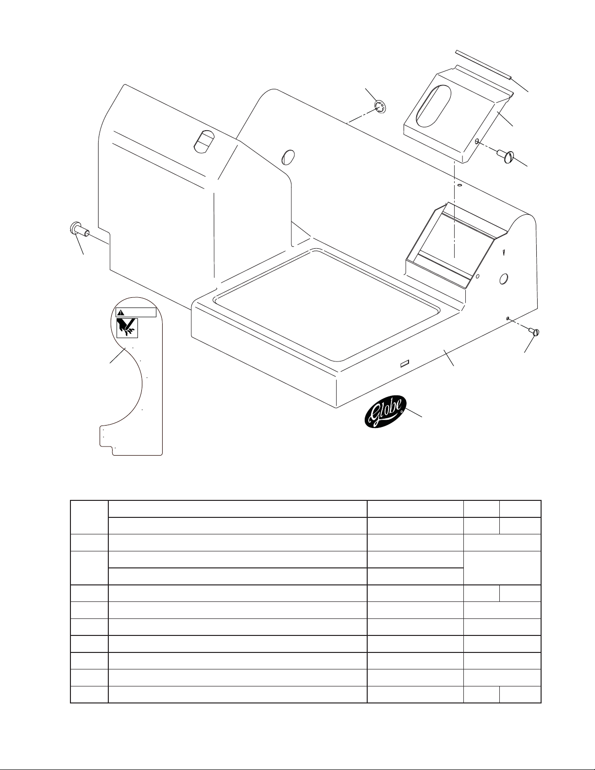
3000N BASE SHROUD AND COMPONENTS
9
5
4
6
8
1
R
MADE IN USA
3
QUANTITY
ITEM PART DESCRIPTION PART NUMBER MAN AUTO
Base Shroud, Manual 330124-01 1 -
1
Base Shroud, Automatic (Not shown) 330124-03 - 1
2 Warning Label, English 910242 1
Warning Label, French (CSA Units) (Not shown) 910243-01
2A
1
Warning Label, Spanish (Option) (Not shown) 910243-02
3 Label, Globe Logo 871-2 - 1
4 Cover, Gauge Plate Mechanism 320071 1
5 Gasket, Gauge Plate Mechanism Cover 530017 1
6 Screw, Gauge Plate Mechanism Cover 900-1 1
7 Screw, Motor Support 762-6 2
8 Screw, Shroud 1227 1
9 Hole Plug, EZ Glide System 890200 1 -
2
Page 6
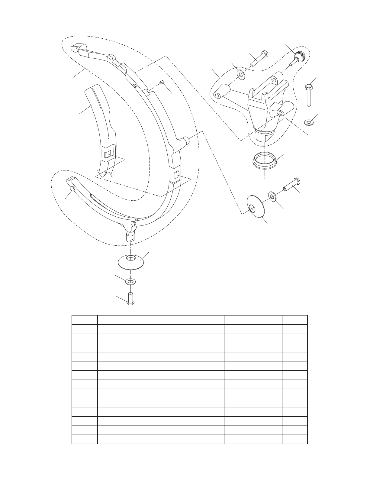
3000N SLICER KNIFE RIM GUARD
1
2
11
12
7
10
14
13
7
9
8
3
7
4
4
5
6
ITEM PART DESCRIPTION PART NUMBER QTY
1 Knife Rim Guard Assembly 520250 1
2 Set Screw 810382 1
3 Locator Pin 460036 2
4 Mounting Boot 520220 2
5 Flat Washer 825-2 1
6 Screw, Button Head 1217 1
7 Flat Washer 825-2 4
8 Screw, Button Head 1217 1
9 Sharpener Bracket Foot 520221 1
10 Rim Guard/Sharpener Mounting Bracket 520261 1
11 Sharpener Release Knob 520330 1
12 Screw, Hex Head 890460 2
13 Product Retainer 520219 1
14 Screw, Hex Head 890470 1
3
Page 7
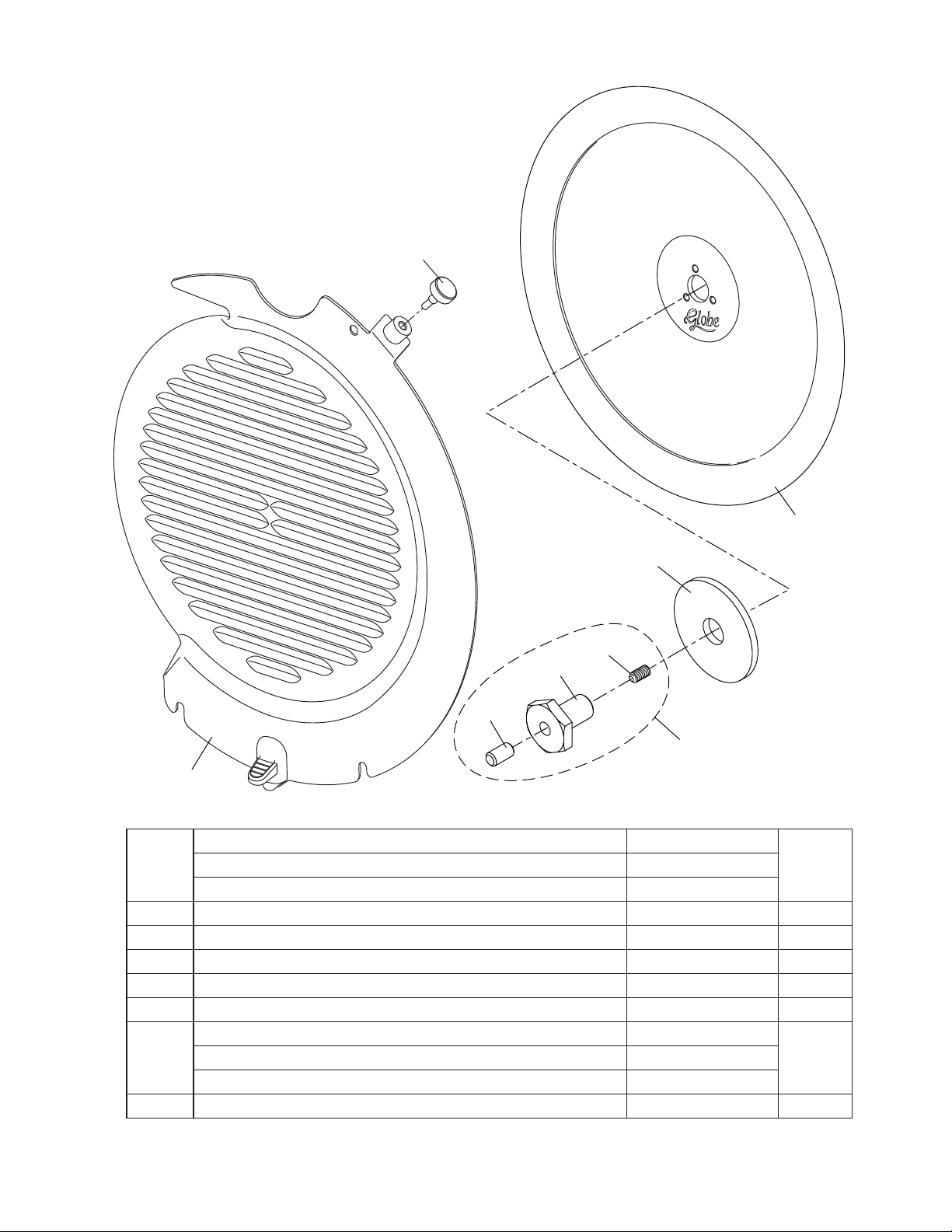
3000N KNIFE AND KNIFE COVER
8
1
2
6
5
4
3
7
ITEM DESCRIPTION PART NUMBER QTY
Carbon Knife 460026
1
Serrated Knife, Carbon Steel (Not shown) *460028
2 Flat Washer 1092 1
3 Knife Bolt Assembly 800001 1
4 Plug 1193 1
5 Bolt 1093 1
6 Set Screw 1194 1
Knife Cover Assembly, Standard (Includes 460045) 330205-01
7
Knife Cover Assembly, Quick Clean (Includes 460045) 330205-03
8 Knife Cover Release Knob (Not used on 330205-02) 460045 1
*Use only on Frozen Meat/Oil Bath & Serrated Knife units.
4
1Stainless Steel Knife 460027
1Knife Cover Assembly, Security 330205-02
Page 8
3000N KNIFE SHARPENER ASSEMBLY COMPONENTS
26
3
25
2
4
29
24
28
22
27
23
11
12
5
6
7
21
14
15
9
10
13
8
Item 1
Knife Sharpener Assembly
20
18
17
16
Item 29
Sharpener Inlay
Used with Serrated Knife
and Security Units
19
ITEM PART DESCRIPTION PART NUMBER QTY
1 Sharpener Assembly with Cover 520240-01 1
2 Sharpener Cover 520222-01 1
3 Sharpener Cover Screw 890340 1
4 Sharpener Housing 520223 1
5 End Cap, Grinding Wheel Shaft 520310 1
6 Spring 890300 1
7 Shaft, Grinding Wheel 460037 1
8 Grinding Wheel, Outside 214-A 1
9 Flat Washer 229 1
10 Jam Nut 890390 1
11 Crescent Ring 890420 1
12 Flat Washer 890430 1
13 Spring 890450 1
14 Sharpener Linkage Assembly 520280 1
15 Pivot, Truing Wheel Shaft 520229 1
16 Spring 890290 1
17 Shaft, Truing Wheel 460037 1
18 Truing Wheel, Inside 213 1
19 Jam Nut 890390 1
20 Shoulder Bolt 890270 1
21 Shaft Pivot 460038 1
22 Retaining Ring (E-Clip) 890490 1
23 Gear, Pivot Drive 520224 1
24 Sharpener Handle with Label and Spring 520226 1
25 Actuating Spring 330123 1
26 Hex Head Screw 890370 1
27 Nut, Nylon Insert 890380 1
28 Sharpener Handle Pivot 460039 2
29
Sharpener Inlay, Standard 340033
Sharpener Inlay, Security 340033-03
1
30 Inlay Mounting Block 340032 1
31 Inlay, Knife Cover 460053 1
32
Screw, Truss Head - Standard Inlay 762-6
Screw, Truss Head - Security Inlay (Not shown) 810180
1
5
32
30
31
Page 9

3000N CARRIAGE ASSEMBLY AND END WEIGHT
10
11
2
13
15
17
19
16
3
18
14
5
4
9
8
1
7
7
6
12
QTY REQD
ITEM PART DESCRIPTION PART NUMBER 12” 14.5”
SS Carriage Assembly, Short - 12” (Standard) Shown 330011-02 1 -
1
SS Carriage Assembly, Medium - 14.5” 330012-01 - 1
2
3
4 Rear Gasket, Carriage Support 510028 1
5 Front Gasket, Carriage Support 510027 1
6 Carriage Support 330055 1
7 Acorn Nut, 1/4-20 962-6 4
8 Lock Back Stud 460050 1
9 Acorn Nut, 5/16-18 962-7 1
10 Handle 482-B 1
11 Acorn Nut, 3/8-16 699-32 1
12 Carriage Release Knob 520312 1
13
14 Endweight Bearing 741-6 2
15 Endweight Handle 510012 1
16
17 Endweight Bumper, Upper 741-5A 1
18 Endweight Bumper, Lower 741-5B 1
19 End Weight Bumper Glide Pin Note 2 810397 1
Note 1: S/Ns lower than listed below use P/Ns 330011-02 (Carriage Assembly), 450025/450046-01 and 741-4a.
Note 2: S/Ns starting with those listed below use P/Ns 330115-02 (Weldment), 450025-02/460047-03, 810396, and 810397.
Serial Numbers: 3600N00800, 3600NF00100, 3850N00500, 3850NF00100 & 3975N00100.
SS Carriage Weldment, Short - 12” Notes 1 & 2 330115-02 1 SS Carriage Weldment, Medium - 14.5” 330116 - 1
End Weight Rod, Short 12” Carriage Assy
End Weight Rod, Medium 14.5” Carriage Assy 450026 - 1
End Weight Assembly, Low Stop Note 1 460047-01
End Weight Assembly, Raised Stop Note 2 460047-03
Side Endweight Bumper, Nylon Note 1 741-4A
Side Endweight Bumper, SS Note 2 810396
Note 1 450025
Note 2 450025-02
1-
1
1
6
Page 10

3000N KNIFE MOTOR BEARING ASSEMBLY
*†15
†16
14
11
13
12
10
10B
9
10A
8
†17
6
7
4
2
5
3
†17
ITEM PART DESCRIPTION PART NUMBER QTY
Knife Bearing Assembly 070049
1
Knife Bearing Assembly, Oil Bath/Serrated Knife Units 070065
2 Knife Locating Hub Assembly 070064 1
3 Upper Bearing Retainer Assembly 070050 1
4 Upper Bearing Retainer 230010 1
5 Standoff 1237 4
6
7 Bearing, Sealed 820045 1
8 Retaining Ring 1088 1
9
10 Knife Shaft 420080 1
10A Key 1106 1
10B Key 1086 1
11
12 Spacer 1083 1
13 Retaining Ring 1087 1
14 Bearing and spacer 800000 1
*†15 Bowed Washer 830010 2
†16 Thrust Washer 820042 1
†17 Screw, Flat Head 890405 4
†18 Retainer, Shroud Gasket 1241 1
19 Gear Lubricant (5.3 oz. Tube) Not Shown) 521-D 1
* Note opposing confi guration: Convex sides of washers touch.
† Item not included with 070049.
Use only on Serrated Knife units.
O-Ring 840020 1
Shaft Seal 840010 1
Gear, Nylon 1084
Gear, Bronze - Oil Bath & Serrated Knife Units
410030
7
1
1
Page 11

12
MADE IN USA
3000N KNIFE MOTOR COMPONENTS
13
14
2
3
10
1
11
4
6
7
15
5
5
ITEM DESCRIPTION PART NUMBER QTY
Knife Motor/Gear Assembly, 115VAC / 60HZ / 1PH 110040
1
Knife Motor/Gear Assembly, 220VAC / 60HZ / 1PH 110042
Knife Motor, 115VAC / 60HZ / 1PH 110100
2
Knife Motor, 220VAC / 60HZ / 1PH 110220
3 Key, Square 1372 1
4 Spacer 460025 1
5 Flat Washer 870070 2
6 Bowed Washer 810 1
7 Worm Gear 1059 1
8 Snap Ring 880051 1
9 Motor Screw 810330 4
Motor Cover 520010
10
Motor Cover with Reset Button Hole (Not shown) *520011
11 Cover Screw 810300 2
12 Wire Connector 1257 1
13 Label, Globe Logo 871-2 1
*14 Motor Reset Button Extension 530015 1
*15 Motor Reset Button Label 796-DS 1
†Used only on units with Motor Reset option.
8
8
9
1Knife Motor/Gear Assembly, 115VAC / 60HZ / 1PH with Reset *110041
1Knife Motor, 115VAC / 60HZ / 1PH with Reset *110101
1
Page 12

3000N SLICER GAUGE PLATE COMPONENTS
17
6
7
5
4
3
15
14
10
8
9
11
1
2
12
13
ITEM PART DESCRIPTION PART NUMBER QTY
Gauge Plate Assembly, Standard 460017-01
1
Gauge Plate Assembly, Security 460017-03
2
3 Gauge Plate Support Replacement Kit 140071 1
4 Gauge Plate Support 210030 1
5 Gauge Plate Fastener Kit 140072 1
6 Gauge Plate Screw 810335 4
7 Gauge Plate Screw Cover 910180 4
8 Flat Washer 870030 2
9 Screw, Gauge Plate Mounting 890408 2
10 Gauge Plate Slide Bracket 450027 1
11 Boot, Gauge Plate Slide 530016 1
12 Gauge Plate Slide Adapter 450020 1
13 Screw, Gauge Plate Slide Adapter 810388 2
14 Screw, Gauge Plate Slide Bracket 810387 1
15 Screw Cap 520314 1
16 Shim Kit (Not shown) 337-A As Reqd
*17 Gauge Plate Fastener, Old Style 976-1 4
*Used before Serial Number 3600N00538, 3850N00180 or 3975N00014.
Gauge Plate, Stainless Steel (Standard/Security) 320015
Gauge Plate, Stainless Steel/Quick Clean 310101
9
1Gauge Plate Assembly, Quick Clean 460017-02
1
Page 13

3000N GAUGE PLATE ADJUSTMENT COMPONENTS
15
17
9
30
12
11
13
16
29
27
8
10
14
28
21
22
3
7
5
23
18
24
20
19
4
6
2
25
1
26
ITEM DESCRIPTION PART NUMBER QTY
1 Gauge Plate Index Knob Assembly 520309 1
2 Molded Index Knob - 1
3 Index Knob Hardware Kit 140073 1
4 Set Screw, Hex Drive - 3
5 Set Screw, Slotted Drive - 3
6 Seal Kit, Index Dial 140074 1
7 Shaft, Index Adjustment Knob 460051 1
8 Worm Gear 1147 1
9 Pin, Worm Gear 360 1
10 Washer, Worm Gear 359 1
11 Ball Bearing 362 1
12 Tension Spring 1200 1
13 Thrust Screw 361-1 1
14 Slide Guide 1259 1
15 Slide Guide Shim Kit (Assorted Thickness) 349-A1 As Reqd
16 Lock Washer 870000 2
17 Screw, Hex Head 1307 2
18
19 Gauge Plate Slide - 1
20
21 Set Screw 168-1 2
22 Nut 760-5 2
23 Stop Screw 1310 1
24 Nut, Stop Screw 478-1 1
25 Screw, Hex Head 975-1 1
26 Set Screw 700-3 2
27 Table Adjustment Gear Assembly 453-AS 1
28 Flat Washer 881-4 1
29 Screw, Hex Head 335 1
30 Set Screw 700-3 1
Gauge Plate Slide Assembly, Standard 420027-01
Gauge Plate Slide Assembly, Meatroom 420027-03
Shaft, Gauge Plate Slide, Standard 1027
Shaft, Gauge Plate Slide, Meatroom 1281
1
1
10
Page 14

3000N CARRIAGE SLIDE SYSTEM COMPONENTS
7
11
10
26
27
2
*6
9
5
18
11
10
34
8
19
12
7
12
24
25
17
16
23
30
31
28
29
31
20
21
Globe
SPECIAL
LUBRICATING
OIL
MEETS F.D.A. REQUIREMENT
DISTRIBUTED BY
GLOBE FOOD EQUIPMENT CO.
DAYTON , OHIO 45439
COLORLESS-ODORLESS-TASTELESS
MADE IN U.S.A.
32
13
QUANTITY
ITEM PART DESCRIPTION PART NUMBER MANUAL AUTO
1 Upper Slide Assembly - Automatic Slicer 1278-A - 1
2 Chain Slide Shaft 1079 - 1
3 Roll Pin 1235 - 1
4 Set Screw 1270 - 2
5 Upper Slide Assembly 1278 - 1
*6 Upper Slide Assembly - EZ Glide 260070 1 -
7 Slide Bushing 436-7 2 2
8 Stud, Slide Rod Bushing 241-B - 1
9 Nut 228 - 1
10 Felt, Oil 436-3 1 1
11 Spring Clip 436-4 1 2
12 Hole Plug 850-3 1 1
13 Lower Slide Bushing 1024 - 1
14 Carriage Receiver Assembly 210026 1 1
15 Shoulder Screw 460039 1 1
16 Lock Washer 245-A 2 2
17 Nut 478-2 2 2
18 Upper Slide Rod 420050 1 1
19 Upper Rod Retaining Clip 857-1 1 1
20 Lower Slide Rod 420060 - 1
*21 Roller Slide Bar, Lower (EZ Glide System) 400070 1 *22 Set Screw (Not shown) 810380 1 -
23 Lower Bar Retaining Clip 858-1 1 1
24 Slide Bar Washer 859 2 2
25 Screw 859-1 2 2
26 Slide Bumper 436-1 1 27 Spring, Sleeved - Upper Slide Rod 919-4 1 2
*28 Bearing 520200 1 *29 Lock Washer 890190 1 *30 Roller, Slide 520210 1 *31 Bolt, Shoulder 810370 2 -
32 Lubricating Oil 519 1 1
11
15
14
Page 15

3000N CARRIAGE DRIVE COMPONENTS, AUTOMATIC SLICER
24
35
36
16
17
31
13
12
7
6
10
9
14
15
8
5
4
2
1
39
33
34
32
29
28
3
11
38
37
18
20
21
19
22
23
ITEM PART DESCRIPTION PART NUMBER QTY
1 Auto/Manual Lever Assembly 1360 1
2 Bracket, Auto Engage 1055 1
3 Cam Assembly 1145 1
4 Fiber Washer 359 2
5 C-Clip 940-10 1
6 Plug 1299 1
7 Spring 1300 1
8 Set Screw, Knurled Cup Point 1291 1
9 Bracket, Microswitch 1053 1
10 Microswitch 1263 1
11 Screw 854-2 2
12 Lock Washer, External Tooth 854-7 2
13 Nut 854-3 2
14 Lock Washer, External Tooth 854-7 2
15 Screw, Truss head 900-1 2
16 Washer, Split Lock 1226 2
17 Screw, Button Head 1217 2
18 Auto-Engage Lever Assembly 1029 1
19 Lever Hub 1026 1
20 Shaft 1028 1
21 Knob 1202 1
22 Set Screw 810393 1
23 Boot, Auto-Engage Lever 520340 1
24 Chain Slide Assembly 1308 1
25 Bearing 1166 2
26 Actuator 1119 1
27 Screw, Flat Head 1089 2
28 Lock Nut 1297 1
29 Lock Washer 962-13 1
30 Eccentric Stud 1080 1
31 Engagement Spring Assembly 1361 1
32 Screw, Hex Head 1295 2
33 Lock Washer 245-A 2
34 Flat Washer 1288 2
35 Lock Washer 1226 2
36 Screw, Socket Head 1238 2
37 Rocker Assembly 1104 1
38 Cam Roller 1102 1
39 C-Clip 940-10 1
12
30
25
26
27
Page 16

3000N CARRIAGE DRIVE MOTOR, AUTOMATIC SLICER
6
5
21
23
22
19
10
4
3
20
24
1
13
12
16
17
11
14
18
2
15
ITEM PART DESCRIPTION PART NUMBER QTY
1 DC Gear Motor 982-1BS 1
2 Drive Chain (Includes Master Link P/N 1336) 1019 1
3 Screw 627-C 4
4 Flat Washer 825-2 4
5 Lock Washer 962-16 4
6 Nut 825-3 4
7 Flat Washer 1288 3
8 Lock Washer 245-A 3
9 Cap Screw 1298 3
10 Motor Mount Bracket 1082 1
11 Sprocket Stud 1118 2
12 Lock Washer 815 2
13 Nut 646 2
14 Motor Sprocket 1030 1
15 18 & 36 Tooth Sprocket 1285 1
16 36 Tooth Sprocket 1286 1
17 Sprocket Washer 608 2
18 Screw 762-6 2
19 Auto Drive Chain Assembly 1020 1
20 Master Link 1336 1
21 Cam Follower 1097 1
22 Flat Washer, Cam 870084 1
*23 Cam Screw 1107 1
24 Wire Connector 982-1MH 1
*Must ship with Washer P/N 870084 (Item 22).
13
9
8
7
Page 17

3000N BASE APRON & LIFT LEVER ASSY, AUTOMATIC SLICER
View from bottom of Slicer
23
12
10
8
7
2
3
5
4
6
1
11
15
19
18
9
20
16
17
14
21
20
ITEM PART DESCRIPTION PART NUMBER QTY
1 Base Apron 1046 1
2 Bolt 813 4
3 Flat Washer 881-4 4
4 Lock Washer 815 4
5 Cover, Electrical Box 520052 1
6 Gasket 1274 1
7 Flat Washer 870087 4
8 Lock Nut, Nylon Insert 810218 4
9 Overlay, Touchpad 1 159 1
10 Gasket 1192 1
11 Cover, Wireway 320041 1
12 Screw 889 7
13 Cover, Bottom (Not shown) 340000 1
14 Lift Lever Assembly 1161 1
15 Lift Lever 1154 1
16 Lift Lever Handle 951-8 1
17 Support, Lift Lever 1155 1
18 Pivot Rod Clip 951-2 2
19 Screw 900-1 4
20 Lock Washer 1252 8
21 Hex Nut 760-5 4
22 Hex Nut 1276 4
23 Clip, Bottom Cover 550010 1
24 Label, Wiring Diagram (Not shown) 910215 1
14
22
Page 18

3000N ELECTRICAL SYSTEM COMPONENTS, MANUAL SLICER
6
7
8
10
13
11
14
9
12
15
1
3A
3
2
P/N 121054
Rev. A
Knife
Motor
J1
J2
Globe Food
J3
Equipment Co.
Dayton, OH
N
RV1
L
J6
K1
R1
R3
R4 C3 R5 R6
D1
Q1
C1
U1
R7
1
1Power Cord, 220V Slicer - US Models 130221
5
4
ITEM PART DESCRIPTION PART NUMBER QTY
1 Control Circuit Board 121054 1
2 Membrane Switch Replacement Kit 980049 1
3 Wireway Cover 320020 1
3A Gasket, Wireway Cover 1192 1
4 Wireway Cover #2 1136 1
5 Wireway Cover #3 1137 1
6 Screw, Wireway Cover 889 14
7 Knife Cover Switch 140030 1
8 Bracket, Sensor 310135 1
9 Screw, Brass 1223 2
10
11 Stand-Off, Motor Start Switch 1250 2
12
13 Ground Screw (Green) 890409 1
14 Lock Washer, External Tooth 854-7 1
15 Strain Relief, Power Cord 877 1
16 Wire Harness, Motor Start Switch (Not shown) 100107 1
17 Wire Harness, Knife Motor (Not shown) 100108 1
18 Wire Harness, Knife Cover Switch (Not shown) 100109 1
Motor Start Switch, 115V Slicer 1179
Motor Start Switch, 220V Slicer 1179-02
Power Cord, 115V Slicer 130205
Power Cord, 220V Slicer - EURO Models 130220
Knife
Cover
T1
J4
R2
C1
J5
J7
15
Page 19

3000N ELECTRICAL SYSTEM COMPONENTS, AUTO SLICER
17
18
19
22
24
23
20
21
10
7
11
4
3
2
1
8
9
6
ITEM PART DESCRIPTION PART NUMBER QTY
1 Power Cord 132-3 1
2 Lock Washer 854-7 2
3 Ground Screw (Green) 890409 2
4 Strain Relief, Power Cord 877 1
5 Wire Harness, 110VAC (Not shown) 130201 1
6 Hex Stand-off, Controller Board Mounting (1/2” Long) 1294 4
7 Lock washer, External Tooth 854-7 4
8 PC Board, Controller/Logic 011002 1
9 Hex Standoff, Power Board Mounting (1.75” Long) 180108 4
10 PC Board, Power Supply, 110VAC 011012 1
11 Nut, Nylon Insert (Power Supply Circuit Board) 1219 4
12 Ribbon Cable, Pwr Bd/Controller Bd (Not shown) 1367 1
13 Ribbon Cable Retaining Clip (Not shown) 180100 2
*14 Cover, Electrical Box, (Not shown) 520052 1
*15 Flat Washer (Electrical Box Mounting, Not shown) 870087 4
*16 Nut, Nylon Insert (Electrical Box Mounting, Not shown) 810218 4
17 Proximity Switch, Knife Cover 1178 1
18 Bracket, Switch Mounting - Knife Guard 310130 1
19 Screw, Knife Guard Bracket 1223 2
20 Switch, Motor Start - Solid State 110VAC 1358 1
21 Stand-Off, Motor Start Switch 1250 2
22 Wireway Cover # 2 1136 1
23 Wireway Cover # 3 1137 1
24 Screw, Wireway Cover 889 7
*Electrical Box and mounting hardware shown with Lift Lever/Apron parts.
16
Page 20

3000N CARRIAGE FENCE ACCESSORIES
1
2
4
5
ITEM DESCRIPTION PART NUMBER QTY
1 Fence Assembly, 12” X 3” 1326 1
2 Fence, 12” X 3” 1048 1
3 Fence Assembly, 12” X 1-3/8” 1047 1
4 Fence, 12” X 1-3/8” 1051 1
5 Clamp Thumb Screw 1052 1
5
3
17
Page 21

3000N VEGETABLE HOPPER ASSEMBLY
ITEM PART DESCRIPTION PART NUMBER QTY
1 Vegetable Hopper Assembly 699-BAS 1
2 Hopper Body with Support and Stud 030041 1
3 Hopper Stop 699-33 1
4 Hopper Stop Screw 900-1 1
5 Hopper Support Knob Assembly 510011 1
5A Flat Washer - 1
5B Knob - 1
5C Nut, Nylon Insert - 1
5D Cap 840002 1
6 Acorn Nut 699-32 1
7 Hopper Handle 482-B 1
8 Hopper End Weight Assembly 699-16 1
9 Hopper End Weight 699-17 1
10 Hopper End Weight Handle 741-SS3 1
18
Page 22

MANUAL SLICER SCHEMATIC, MODEL 3600N
P/N 140030
P/N 1049
KNIFE MOTOR
1179
1179-02
BLU
MOTOR
START SWITCH
123
123
RED
BLK
KNIFE COVER SENSOR
WIRE HARNESS
P/N 100107
J1 J2
Motor
Knife
J4
Knife
J2
J1
1
Cover
Globe Food
Equipment Co.
J3
J4
T1
R2
R1
Dayton, OH
RV1
N
2
J5
C1
U1
C1
R3
J6
L
WIRE HARNESS
P/N 100109
J7
J7
R7
R4 C3 R5 R6
Q1
D1
K1
P/N 121054
Rev. A
MEMBRANE SWITCH
KIT P/N 980049
110041
110040
130221 110220
Electrical Parts Application Table
115VAC, 7A 130205
220 VAC, 3.5A
US
CSA
Style Model Power Cord Knife Motor Motor Start Switch
EURO 130220 110221
YEL
P/N 100108
WIRE HARNESS
19
J3
WHT
AC POWER CORD
(P/N 130205 Standard)
J6
BLK
GRN
P/N 121054
PRINTED CIRCUIT BOARD
Page 23

AUTOMATIC SLICER SCHEMATIC - MODELS 3850N & 3975N
P/N 130205
POWER CORD
GRN
BLK
P/N 110040
KNIFE MOTOR
P/N 982-1BS
CHUTE MOTOR
1/10 HP, 90VDC MAX
AC
115V
WHT
WHT
BLK
YELLOW
RED
MTR
BLUE
WHT
+
MTR 2
-
BLK
NOT USED
WHT
NEUTRAL
NOT USED
FRAME GROUND
NOT USED
115 VAC
BLK
P3
P3-7
P3-8
J1
J1-1P3-1
J1-2P3-2
J1-3P3-3
J1-4P3-4
J1-5P3-5
J1-6P3-6
J1-7
J1-8
YELLOW
RED
RED
GRAY
BLUE
1 23
BLK
VIOLET
VIOLET
P2
P2-1
J4
J4-1
POWER SUPPLY BOARD
YELLOW
P/N 1358
SOLID STATE
MOTOR START SWITCH
YELLOW
(-)
CHUTE MOTOR
P2-2
J4-2
YELLOW
P2-3
J4-3
CHUTE MOTOR
J2
P1-10
P1-9
P1-8
P1-7
P1-6
P1-5
P/N 011012
P1-4
P1-3
P1-2
3000 SERIES AUTO SLICERS
P1-1
(+)
P2-4
J4-4
KNIFE RELAY
CHUTE RELAY
CHUTE DRIVE
POT
+5VDC
S1
FET TEMP
+VS
GROUND
CHUTE V
3850
8
7
6
3
N
All switches ON
CONTROLLER BOARD
12 45
O
DIP SWITCH SETTINGS
8
7
6
3
12 45
O
3975
N
1 OFF, all others ON
CONTROLLER/LOGIC BOARD
USE WITH WIRE HARNESS P/N 130201
& AUTO ELECTRIC ENCLOSURE P/N 520052
J1
J1-1
J1-2
J1-3
J1-4
J1-5
J1-6
J1-7
J1-8
J1-9
J1-10
J4
J4-1
P/N 011002
J4-2
J4-3
3000 SERIES AUTO SLICERS
J4-4
J4-5
20
P1
P1-1
P1-2
P1-3
P1-4
P1-5
P1-6J4-6
CHUTE SWITCH
GROUND
GUARD SWITCH
GROUND
NOT USED
NOT USED
WHT/BLUE
BLUE
WHT
WHT
NC
COM
CHUTE
SWITCH
P/N 1263
GUARD
SWITCH
P/N 1178
Page 24

NOTES
Page 25

Page 26

995058 GFE-3600N, 3850N & 3975N Rev B ECN 1805 13Dec2013
 Loading...