

Global VR Blazing Angels Green Label WWII Operation & Service Manual
Blazing Angels
Operation & Service Manual
© 2008 Ubisoft Entertainment. All Rights Reserved. Blazing Angels, Ubisoft, and the Ubisoft logo are trademarks of Ubisoft Entertainment in the U.S.
and/or other countries. GLOBAL VR and the GLOBAL VR logo are registered trademarks of Global VR, Inc. All Rights Reserved. All other trademarks are
the properties of their respective owners.
¾ Read this manual before use.
¾ Keep this manual with the machine at all times.
040-0168-01 Rev. B
www.globalvr.com
http:
//
service.globalvr.com
techsupport@globalvr.com
Phone: 408.597.3435
Fax: 408.597.3437

Table of Contents
Table of Contents
Preface...................................................................4
Safety..................................................................4
Warnings.........................................................4
Environmental Conditions..............................4
FCC Notices (United States)..............................5
Chapter 1 — Introduction....................................6
Game Features:...................................................6
Hardware Features: ............................................6
Current Requirements (Approximate)................6
Chapter 2 — Installing a New Cabinet................7
Cabinet Installation ............................................7
Checking the Game Dongle ...............................9
Chapter 3 — Flying a Mission...........................10
Chapter 4 — Operator Menu and Game
Setup ............................................................12
Navigating the Operator Menu.........................12
Operator Main Menu........................................14
System T est Menu............................................15
Coin Audits Menu ............................................18
Game Audits Menu ..........................................19
Coinage Adjustments Menu .............................20
System Adjustments Menu...............................21
Game Adjustments Menu.................................22
Reset Menu.......................................................23
Audio Amp PCB Replacement.....................32
Front (Marquee) Speaker Replacement........32
Rear (Seat) Speaker Replacement................32
Seat Subwoofer Replacement....................... 33
Seat Knocker or Fuse Replacement................. 33
Knocker Relay PCB Replacement................34
Computer Replacement ................................... 34
LCD Monitor Assembly Service .....................35
Glass Display Shield Replacement............... 35
Monitor Replacement................................... 35
Monitor Control PCB Replacement ............. 37
Monitor Power Supply Replacement............37
Coin Mech Replacement ................................. 38
Coin Meter Replacement.................................38
Power Distribution Service.............................. 38
AC Power Plate............................................38
AC Power Strip Replacement....................... 39
DC Power Supply Replacement...................40
Marquee Florescent Light Service...................40
Exhaust Port LED Service............................... 41
Front Instrument Panel LEDs..........................41
Side Instrument Panel LEDs............................ 41
Tail Light Replacement....................................42
Cold-Cathode Florescent Light Service........... 42
CCFLs Behind Rear Marquee......................42
Speaker Lights..............................................42
Setting the Computer BIOS (CMOS).............. 43
Chapter 5 — Software Restoration....................24
Chapter 6 — Service and Repair .......................25
Access Panels on Cabinet Rear........................25
Calibrating the Joystick and Throttle ...............26
Joystick Service................................................27
Replacing Joystick Grip................................27
Replacing Joystick Pots ................................27
Throttle Service................................................28
Replacing the Throttle Pot or Gear Wheel....28
Replacing the Throttle Handle......................29
GVRI/O Mini PCB Service..............................30
Audio Amp and Speakers Service....................31
Blazing Angels Operation and Service Manual
Page 2 of 64 040-0168-01 Rev. B 3/14/2008
Chapter 7 Troubleshooting................................. 46
V ideo Troubleshooting.................................46
Audio Troubleshooting................................. 47
Control Troubleshooting...............................48
Miscellaneous Troubleshooting.................... 48
Chapter 8 — Replacement Parts ....................... 50
Chapter 9 — Diagrams and Schematics............ 55
Warranty Service................................................. 63
LIMITED WARRANTY.................................63
Technical Support ............................................... 64

List of Figures
List of Figures
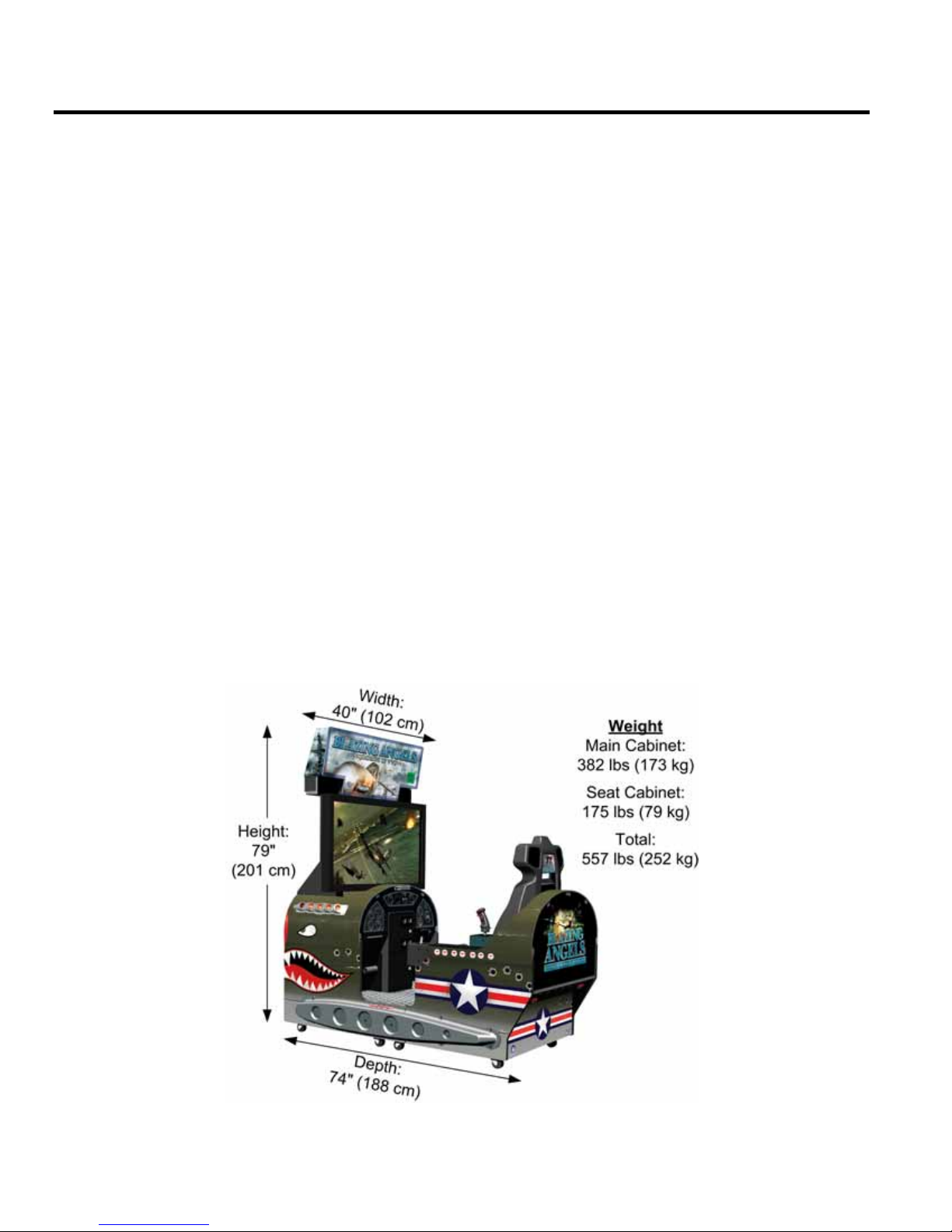
Figure 1. Cabinet Dimensions............................. 6
Figure 2. Coin Door with Key Location ............. 7
Figure 3. USB Game Dongle..............................9
Figure 4. Operator Button Panel ....................... 12
Figure 5. Operator Menu Flowchart..................13
Figure 6. Operator Main Menu .........................14
Figure 7. System T est Menu..............................15
Figure 8. Coin Audits Menu.............................. 18
Figure 9. Game Audits Menu............................19
Figure 10. Coinage Adjustm ents Menu...............20
Figure 11. System Adjustme nts Menu ................ 21
Figure 12. Game Adjustments Menu ..................22
Figure 13. Reset Menu........................................23
Figure 14. Cabinet Rear......................................25
Figure 15. Location of Primary Electronic
Components .............................................. 26
Figure 16. Joystick Assembly Details.................28
Figure 17. Throttle Pot and Gear Assembly........29
Figure 18. Replacing the Throttle Handle...........29
Figure 19. GVRI/O Mini PCB............................ 30
Figure 20. Audio Amp and Speakers..................31
Figure 21. Knocker Solenoid Assembly..............33
Figure 22. Monitor Assem bly Exploded View.... 35
Figure 23. Monitor Mounting Bolts ....................36
Figure 24. Monitor and Backbox Components ...36
Figure 25. Servicing the Coin Mech and Coin
Meter .........................................................38
Figure 26. AC Power Plate..................................39
Figure 27. Marquee Assembly Exploded View...41
Figure 28. Cold-Cathode Light Detail.................42
Figure 29. Artwork Part Numbers.......................52
Figure 30. Joystick Exploded View and Parts.....53
Figure 31. Throttle Exploded View and Parts .....54
Figure 32. Computer Rear Panel Diagram..........55
Figure 33. Sim plified Wiring Diagram................56
Figure 34. Detailed Wiring Diagram...................57
Figure 35. Power Distribution Diagram..............58
Figure 36. Main Cabinet Assembly
(Page 1 of 2).............................................. 59
Figure 37. Main Cabinet Assembly
(Page 2 of 2).............................................. 60
Figure 38. Seat Cabinet Assembly
(Page 1 of 2).............................................. 61
Figure 39. Seat Cabinet Assembly
(Page 2 of 2).............................................. 62
©2007 Global VR, Inc.
040-0168-01 Rev. B 3/14/2008 Page 3 of 64

Preface
Preface
Safety
The following safety instructions apply to all game operators and service personnel. Specific warnings and cautions will
be included throughout this manual.
Use the following safety guidelines to help protect the system from potential damage and to ensure your personal safety:
• Electronic components in the game cabinet run on 115 VAC. The voltage switch on the back of the computer must
• To help prevent electric shock, plug the system into a properly grounded power source. These cables are equipped
• To help protect your system from sudden increases and decreases in electrical power, use a surge suppressor, line
• Be sure nothing rests on the system's cables and that the cables are not located where they can be stepped on or
Please read this page before preparing your arcade cabinet for game play.
be set to 115. If you power up the computer outside of the cabinet, set the switch to match the local AC voltage:
− 115 volts / 60Hz in most of North and South America and some Far Eastern countries such as Japan, South
Korea and Taiwan
− 230 volts / 50Hz in most of Europe, the Middle East and the Far East
with 3-prong plugs to help ensure proper grounding. Do not use adapter plugs or remove the grounding prong from
a cable. If you must use an extension cable, use a 3-wire cable with properly grounded plugs.
conditioner or Uninterruptible Power Supply (UPS).
tripped over.
• Keep your system far away from radiators and other heat sources.
• Do not block cooling vents.
Precautions for Game Operation
GLOBAL VR® assumes no liability for injuries incurred while playing our games.
Operators should be aware that certain health and physical conditions may make people susceptible to injury when
playing video games, particularly when the game moves or creates a sense of motion.
Warnings
To avoid electric al shock, unplug the cabinet before performing
installation or service procedures.
If the power cord is damaged, it must be replaced by the equivalent
power cord available from GLOBAL VR or your distributor.
GLOBAL VR® assumes no liability for any damages or injuries incurred
while setting up or servicing the cabinet. Only qualified service
personnel should perform installation or service procedures!
Environmental Conditions
Cabinet is intended for indoor use only. Be sure to keep the cabinet dry and maintain operating temperatures of
59°-86° F (15°-30° C).
Blazing Angels Operation and Service Manual
Page 4 of 64 040-0168-01 Rev. B 3/14/2008

Preface
FCC Notices (United States)
Electromagnetic Interference (EMI) is any signal or emission radiated in free space or conducted along power or signal
leads, that endangers the functioning of radio navigation or other safety service, or that seriously degrades, obstructs, or
repeatedly interrupts a licensed radio communications service. Radio communications services include, but are not
limited to, AM/FM commercial broadcast, television, cellular services, radar, air-traffic control, pager, and Personal
Communication Services (PCS). These licensed services, along with unintentional radiators such as digital devices
(including computer systems) contribute to the electromagnetic environment.
Electromagnetic Compatibility (EMC) is the ability of items of electronic equipment to function properly together in the
electronic environment. While this computer system has been designed and determined to be compliant with regulatory
agency limits for EMI, there is no guarantee that interference will not occur in a particular installation. If this equipment
does cause interference with radio communications services, which can be determined by turning the equipment off and
on, you are encourage d to try to correct the interf erence by one or more of the following measures:
• Re-orient the receiving antenna.
• Relocate the cabinet relative to the receiver.
• Plug the game into a different outlet so that the computer and the receiver are on different branch circuits.
®
If necessary, consult a Regulatory EMC representative of GLOBAL VR
for additional suggestions. You may find the FCC Interference Handbook
Government Print Office, Washington, DC 20402.
This device has been tested and complies with the limits for a Class A digital device pursuant to Part 15 of the FCC
Rules. These limits are designed to provide reasonable protection against ha rmful interference when the equipment is
operated in a commercial environment. This equipment generates, uses, and can radiate radio frequency energy. If not
installed and used in accordance with the instruction manual, it may cause harmful interference with radio
communications. Operation of this equipment in a residential area is likely to cause harmful interference, in which case
you will be required to correct the interference at your own expense.
Operation is subject to the following conditions:
• This device may not cause harmful interference.
or an experienced radio/television technician
, to be helpful. It is available from the U.S.
• This device must accept any interference received, including interference that may cause undesired operation.
©2007 Global VR, Inc.
040-0168-01 Rev. B 3/14/2008 Page 5 of 64
Chapter 1 — Introduction
Chapter 1 — Introduction
Green Label WWII Arcade Action Comes to Life in Blazing Angels: Squadrons of WWII
Take to the skies in a WWII fighter plane and test your combat skills in World War II battles.
Test your mettle as a fighter pilot in a Dogfight or six WWII Campaigns (easy, medium or hard
difficulty) that include London, Africa, Pearl Harbor, Midway, Rabaul and Ardennes.
Beat a medium or hard scenario and fly an amazing bonus level…Berlin.
Game Features:
• Fly realistic WWII planes
• Flight m odel is realistic yet easy to control….Perfect for beginners or experienced pilots
• Clearly marked targets make it easy to locate enemies
• 360 degree battlefield gives players a full flight model
• Multiple mission objectives are communicated to players via text and chatter
• Unlimited ammo...…no reloading Machine Guns
Hardware Features:
• 42” LCD HD monitor
• Realistic controls
• Seat Solenoid / Force Feedback seat
Current Requirements (Approximate)
• Voltage: 115 VAC
• Voltage: 230 VAC
Inrush AC Current: 8 Amps Operating AC Current: 5 Amps
Inrush AC Current: 4 Amps Operating AC Current: 3 Amps
• 5.1 surround sound
• Cabinet looks like a WWII fighter,
complete with kills marker
Blazing Angels Operation and Service Manual
Page 6 of 64 040-0168-01 Rev. B 3/14/2008
Figure 1. Cabinet Dimensions
Chapter 2 — Installing a New Cabinet
Chapter 2 — Installing a New Cabinet
Cabinet Installation
Use the following procedure to install and set up your game:
1. Carefully remove the Main Cabinet and Seat Cabinet from the shipping boxes, giving yourself
plenty of space. Inspect the exterior of the cabinets for any damage.
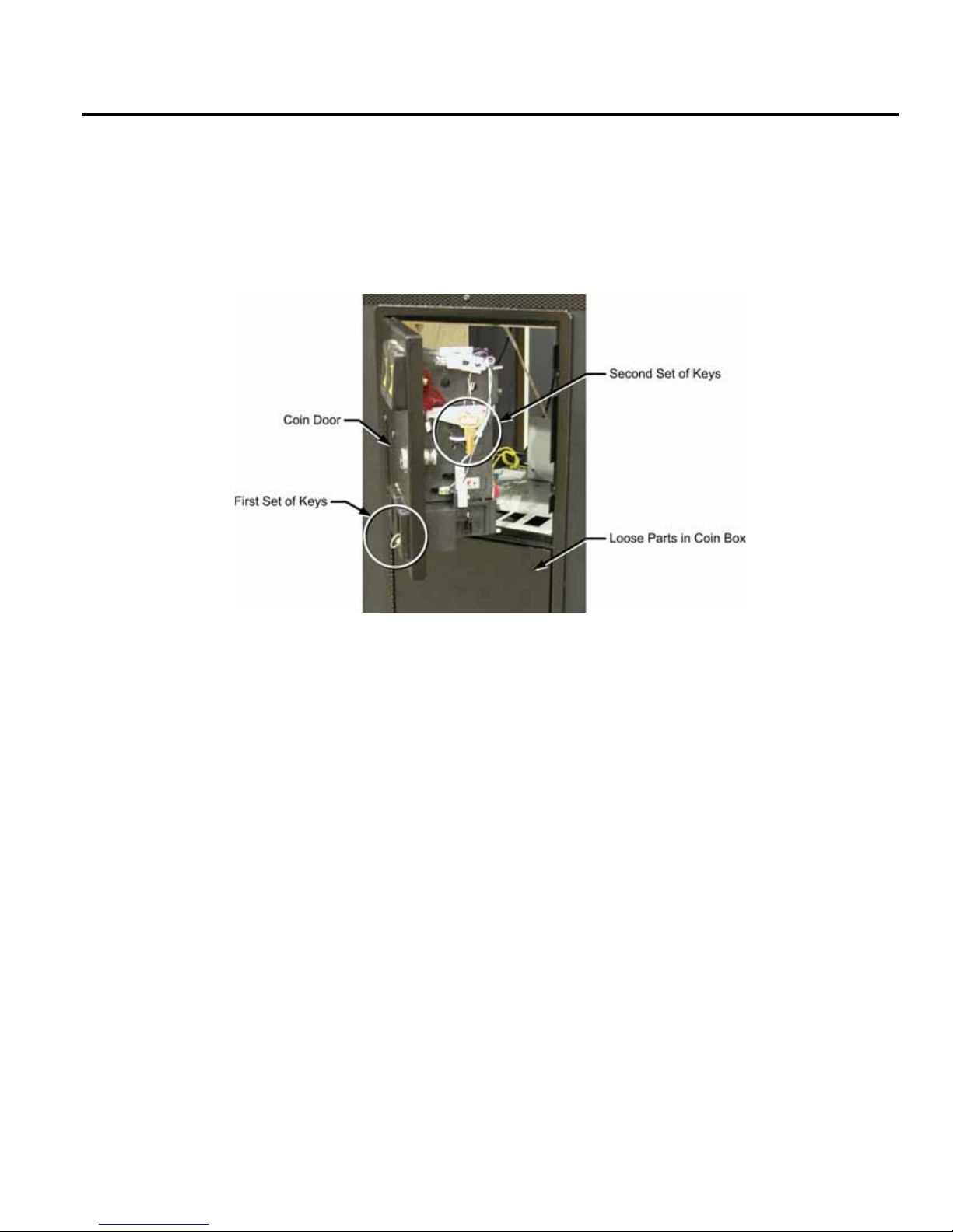
2. Remove the keys from the coin return slot. Open the coin door to locate the second set of keys.
Figure 2. Coin Door with Key Location
3. Locate the following items (small hardware items should be in the coin box):
• Two (2) Connector Brackets
• Two (2) Wing Assemblies
• 28 ¼-20 x 1-¼" bolts
• 12 each Flat Washers & Lock Washers
• 16 1" Fender Washers
• AC Power Cord
4. Locate the following documents and software:
• System Manual (This Document)
• Software Restore Guide
• System & Game Install Disk
5. Move the Main Cabinet and Seat Cabinet so they face each other, about 12-inches apart.
6. Locate the Five (5) cables tied inside the area under the floor of each cabinet and connect the
corresponding connectors.
• 4-Pin PC Power (Rear Marquee Power)
• 6-Pin Molex (Special Lighting)
• 2-Pin Molex (Knocker Control)
• 3-Pin Molex (Ground Wires)
• 15-Pin Molex (Player Controls)
7. Carefully push the Main Cabinet and Seat Cabinet together, being careful not to pinch any
cables.
8. Connect the AC power cord from the AC Power Plate on the back of the cabinet to a grounded
(3-terminal) AC wall outlet.
©2007 Global VR, Inc.
040-0168-01 Rev. B 3/14/2008 Page 7 of 64
Chapter 2 — Installing a New Cabinet
9. Power ON the cabinet using the ON/OFF switch on the AC Power Plate. Verify that the game
boots properly.
Note: Instrument panel and exhaust port lighting will not come on until the Attract Mode
starts.
10. Once the Attract movie starts, press the Operator TEST button to open the Operator Menu.
Select System Tests and make sure all controls and coin inputs are working.
11. Play a game to verify proper operation. Calibrate joystick and throttle if needed (see page 26).
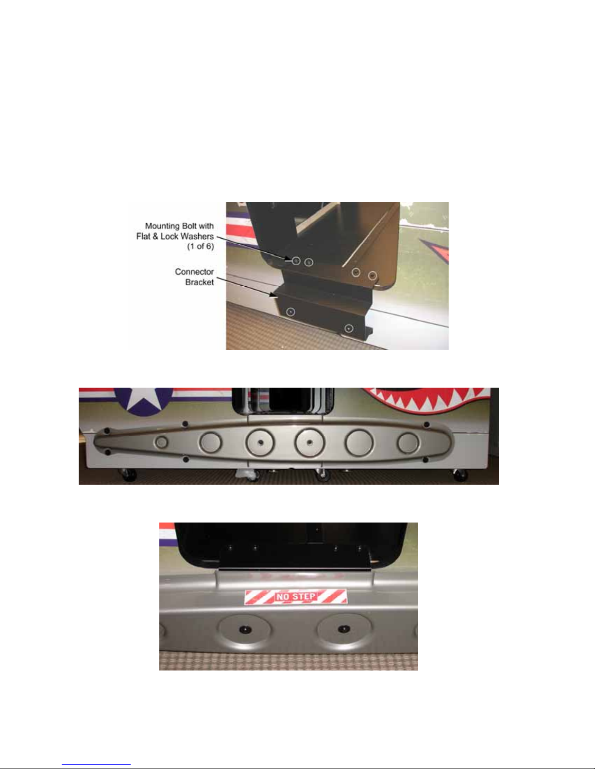
12. Place a Connector Bracket over the seam between the two cabinets, as shown below, and secure
it using six (6) ¼-20 x 1-¼" bolts with flat and lock washers. Repeat for the other side.
13. Place the wing as shown below, with the NO STEP Decal facing up, if already applied, and
secure it with the eight (8) ¼-20 x 1-¼" bolts with 1" fender washers.
14. If the NO STEP Decal was not already applied, apply it to the top of each wing, aligned with the
player entry, as shown below:
15. The game is now ready to play. Enter the Operator Menu to set up pricing and other Operator
Settings.
Blazing Angels Operation and Service Manual
Page 8 of 64 040-0168-01 Rev. B 3/14/2008
Chapter 2 — Installing a New Cabinet
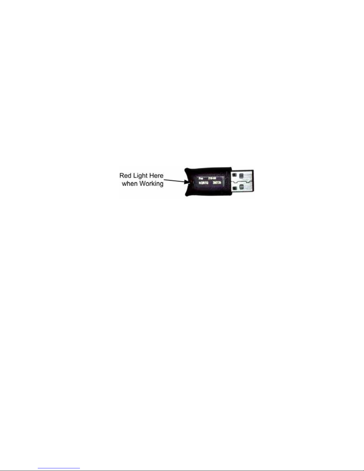
Checking the Game Dongle
The cabinet uses a Game Dongle to activate the game software. If the dongle is missing, the
game will not run. When a USB Game Dongle is installed and working properly, a red LED
will illuminate inside the dongle.
For a Game Dongle to be recognized correctly, it should be connected before the cabinet is
powered ON. If the software does not recognize the Game Dongle, make sure the Dongle is
connected properly, and then power cycle the cabinet to see if this resolves the problem.
If the dongle should come out while the game is running, a NO DONGLE screen will appear. If
this happens, the dongle can be re-installed without rebooting the game.
Note: The dongle supplied with the cabinet is specific to the game software version. Future
software upgrades may require a new dongle.
Important: Some of your cabinet information is stored in the dongle, so if you replace your
computer, remove the dongle and keep it with the cabinet.
Figure 3. USB Game Dongle
©2007 Global VR, Inc.
040-0168-01 Rev. B 3/14/2008 Page 9 of 64
Chapter 3 — Flying a Mission
Chapter 3 — Flying a Mission
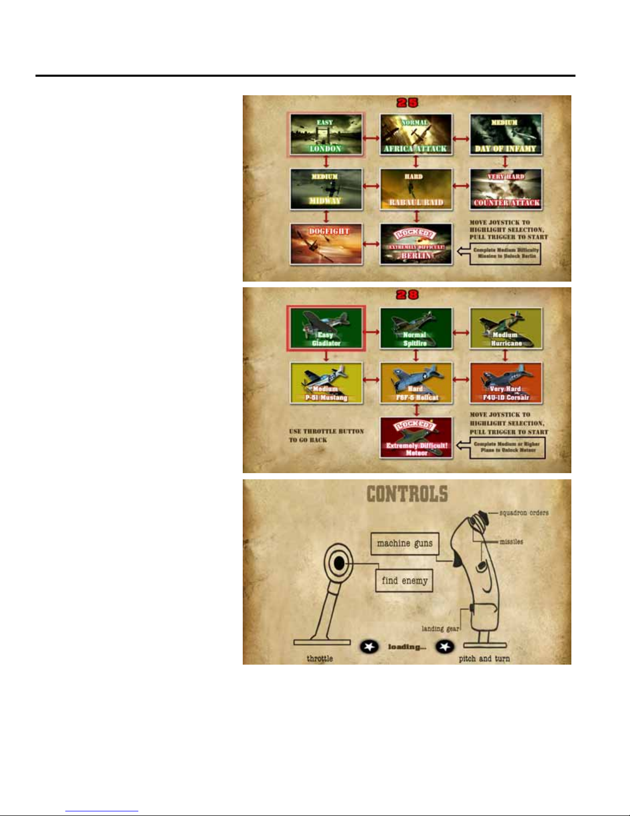
Coin up the game and then pull the
trigger; the Select Mission screen
will appear. Each mission is rated
by difficulty.
Move the joystick to highlight a
Campaign mission, or select
Dogfight, and then pull the trigger
to select your choice.
If you select Dogfight, the Dogfight
menu will appear. Use the joystick
to select your plane, and pull the
trigger. Each plane is rated by the
difficulty of the mission.
As the game loads, the Controls
screen will appear, showing the
function of the buttons on the
joystick and throttle.
Blazing Angels Operation and Service Manual
Page 10 of 64 040-0168-01 Rev. B 3/14/2008

Chapter 3 — Flying a Mission
• Once the game loads, use the Joystick and throttle to control your flight and speed.
• Line up enemies in the targeting scope and pull the trigger. You have unlimited machine gun ammo so
you never need to reload. You can have up to eight missiles loaded, but once fired there is a delay
before they reload.
• Press the button on the throttle to change the view and show you your current target. (A hint screen
will appear to explain this function if the player doesn't use it.)
• Targets that are out of range are highlighted in yellow. They change to red when in gun range.
(Friends are highlighted in green.)
• You can use the joystick "hat" (the top button) to send "squadron orders" to your wingmen, for
Formation, Attack, or Defense.
• If time runs out before you complete the mission, or if you are shot down, you will have 15 seconds to
insert coins and continue.
• Players who do well can enter their names for the high score screen.
The screen below shows the information that appears onscreen during a Dogfight mission:
The screen below shows the information that appears onscreen during a Campaign mission:
©2007 Global VR, Inc.
040-0168-01 Rev. B 3/14/2008 Page 11 of 64
Chapter 4 — Operator Menu and Game Setup
Chapter 4 — Operator Menu and Game Setup
This chapter describes how to use the Game Operator menu to set up the game, diagnose problems,
and view gameplay and earnings statistics.
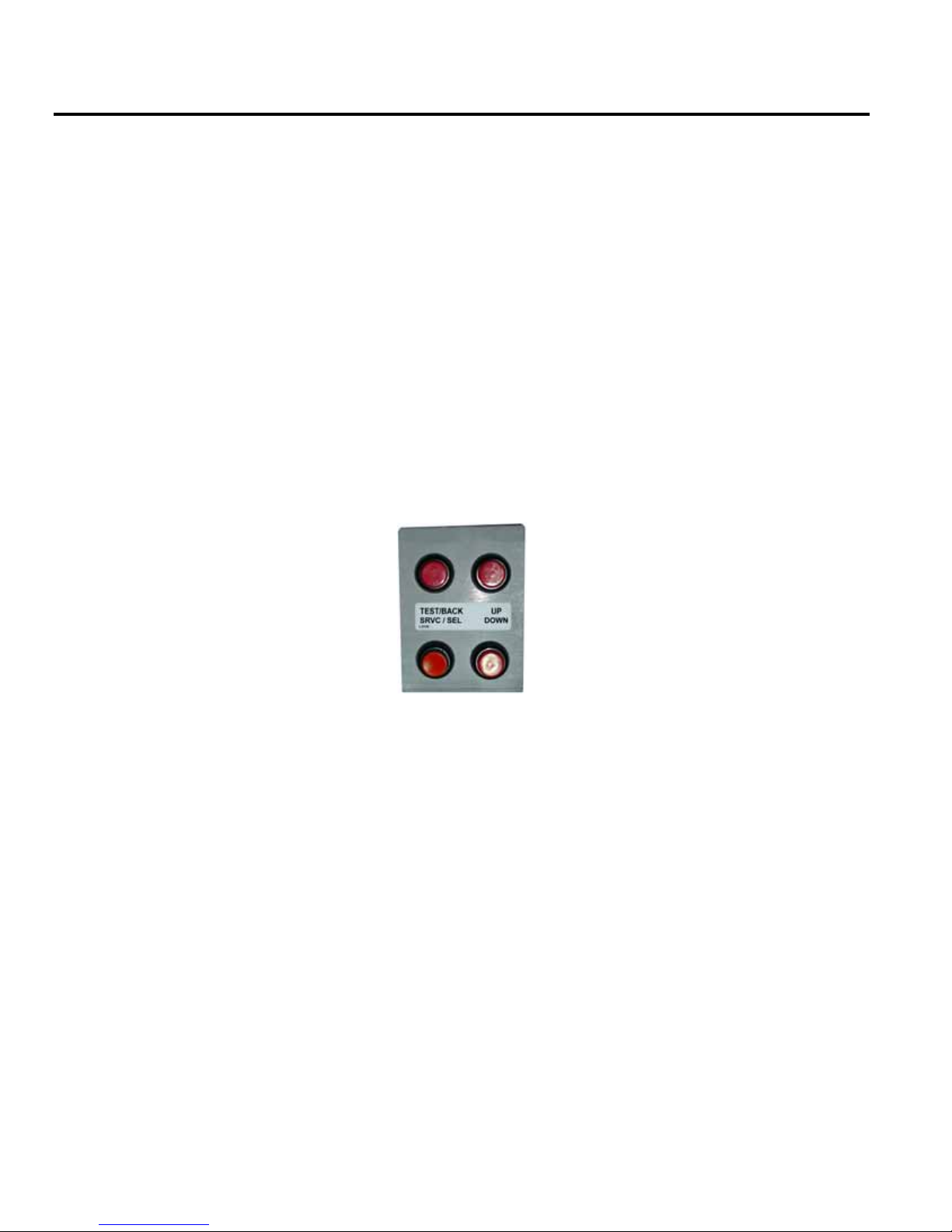
Navigating the Operator Menu
1. With the game running in Attract Mode, open the coin door and press the TEST/BACK button
on the Operator Button Panel to open the Operator Main Menu.
2. Use the UP and DOWN buttons to move through the list and highlight a submenu, and then
press the SRVC/SEL button to open the submenu.
3. Note the onscreen instructions at the bottom of each menu screen. This text will change to help
you use the menu items.
4. To change a setting, highlight the item, press SERV/SEL, and then use the UP and DOWN
buttons to cycle through the available settings. Press SERV/SEL to accept the selected setting.
5. When you wish to exit, highlight Back to Main Menu and press SRVC/SEL, and then highlight
Exit to Game on the Main Menu and press SRVC/SEL. (Hint: Pressing TEST/BACK from
any menu will automatically take you to the last item in the list.)
Figure 4. Operator Button Panel
Blazing Angels Operation and Service Manual
Page 12 of 64 040-0168-01 Rev. B 3/14/2008

Chapter 4 — Operator Menu and Game Setup
Main Menu
System Tests Menu
Coin Audits
Game Audits
Coinage
Adjustments
System Adjustments
Game Adjustments
Reset Menu
Displays System Test Menu.
Displays coin and service credit totals.
Displays gameplay stats.
Sets pricing and Insert Coin message.
Turns Free Play on or off.
Sets up audio, video gamma, seat
knocker solenoid, and instrument lights.
Sets camera shake, and minimum time
per credit.
Displays restart time information.
Resets credits, audits, or adjustments,
or restores factory defaults.
Calibrate Flightstick
Switch Input Test
Output Test
Video Screen Test
Sound Test
Exit to Game
Returns to Game Attract Mode.
Figure 5. Operator Menu Flowchart
©2007 Global VR, Inc.
040-0168-01 Rev. B 3/14/2008 Page 13 of 64
Chapter 4 — Operator Menu and Game Setup
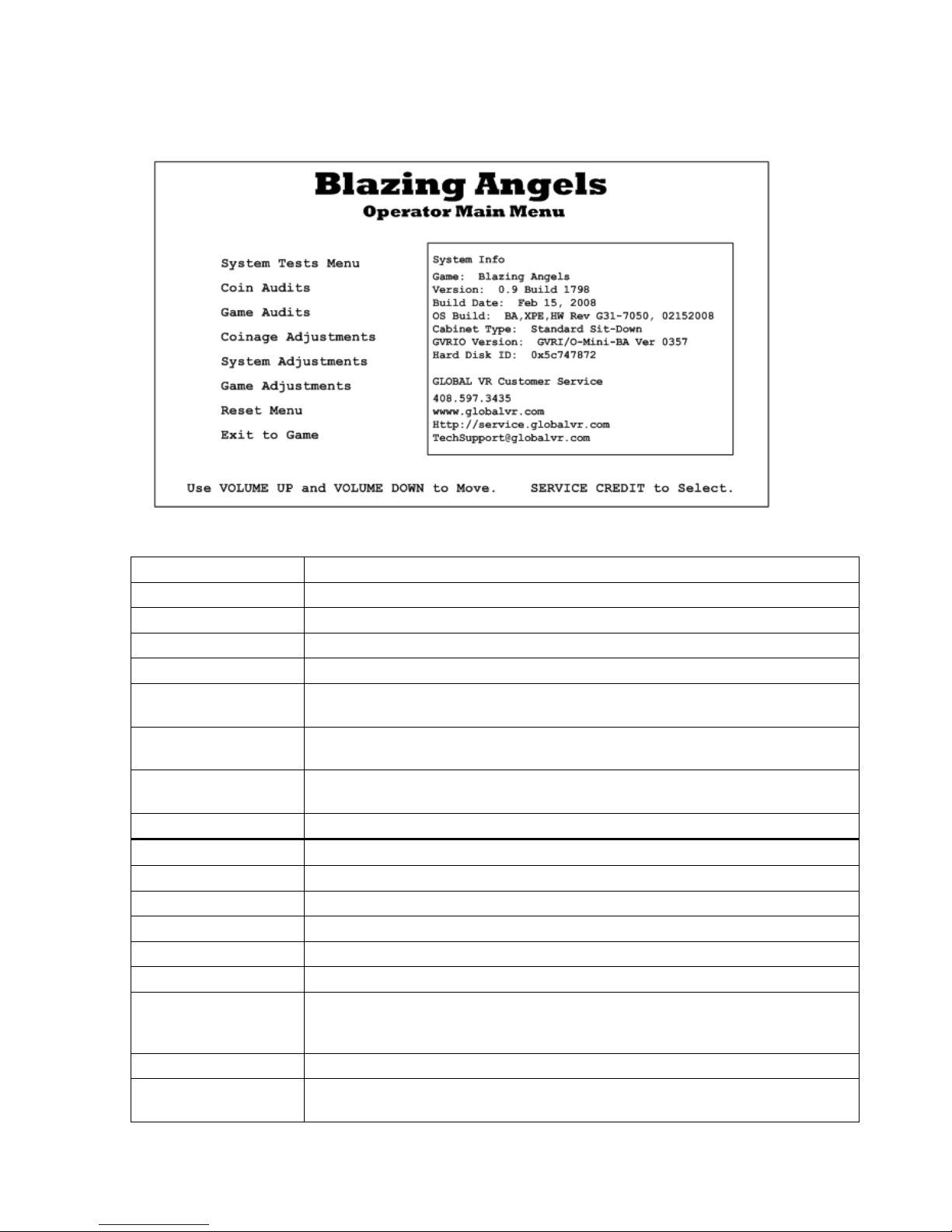
Operator Main Menu
This screen displays information about the game and provides access to the other menus.
Figure 6. Operator Main Menu
Menu Item Description
System Tests Menu Lets you calibrate the joystick and test controls and audio (see page 15).
Coin Audits Displays coin count stats (see page 16).
Game Audits Displays stats on games and levels played (see page 19).
Coinage Adjustments Lets you set pricing and change the Insert Coin message (see page 20).
System Adjustments Lets you adjust audio settings, video gamma, turn knocker solenoid on or off,
and set instrument panel lights to flicker or stay on (see page 21).
Game Adjustments Lets you adjust ramp time to maximum game difficulty, camera shake, and
minimum time per credit (see page 22).
Reset Menu Lets you reset high scores, stats, credits, adjustments, or restore factory
default settings (see page 23). Displays software restart information.
Exit to Game Exits to Game Attract Mode.
System Info
Game Name of the game installed.
Version Game software version and build.
Build Date Date of software build.
OS Build Name and date of the Operating System build.
Cabinet Type Type of cabinet.
GVRIO Version Version of GVRI/O Mini PCB installed. The letters "BA" indicate that the
Hard Disk ID ID of the hard disk in the system computer.
GLOBAL VR
Customer Service
This box displays information about the cabinet software and hardware.
firmware is for Blazing Angels. The game will not work with a PCB that does
not have Blazing Angels firmware and Version 0357 or later.
Contact info for Customer Service, as well as the GLOBAL VR website URLs.
Blazing Angels Operation and Service Manual
Page 14 of 64 040-0168-01 Rev. B 3/14/2008
Chapter 4 — Operator Menu and Game Setup
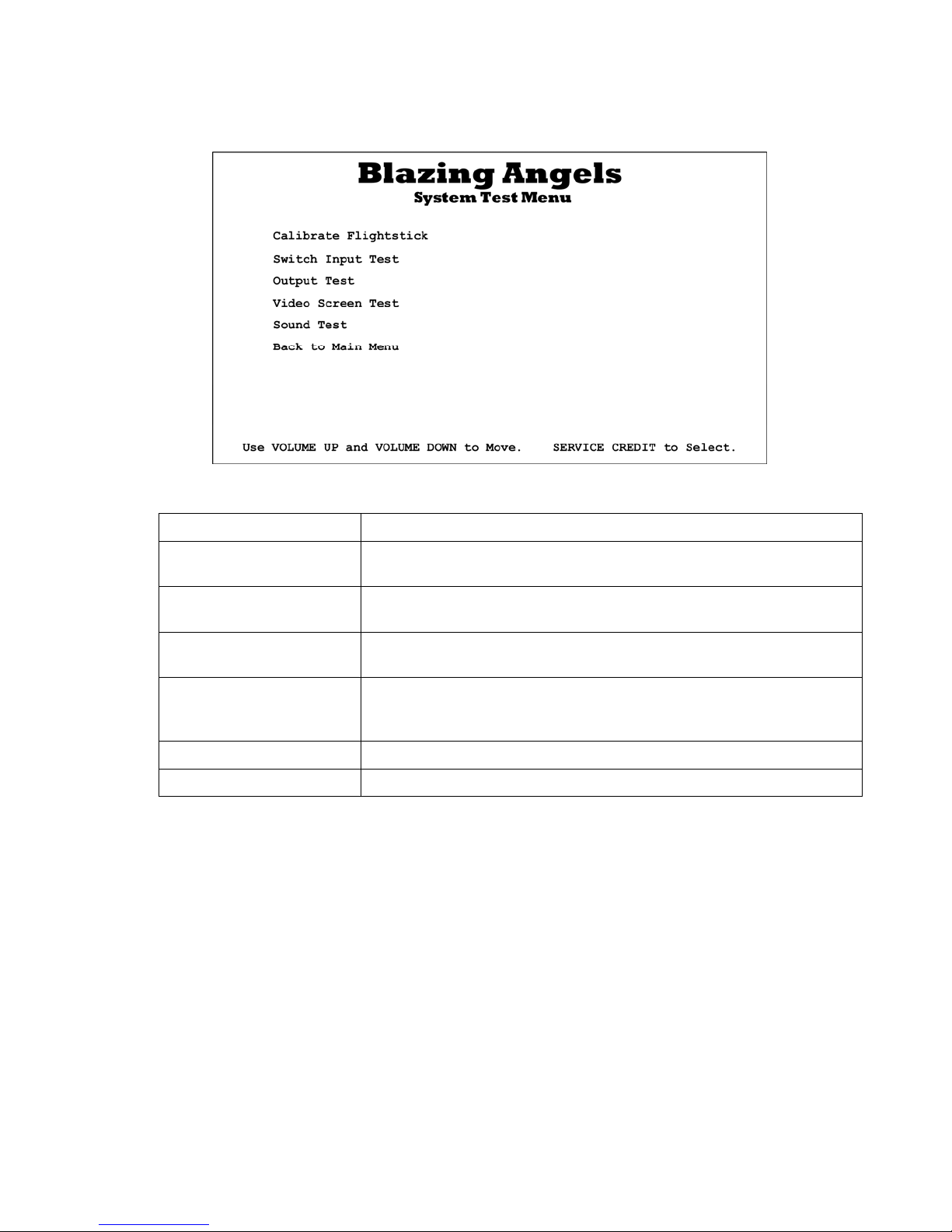
System Test Menu
This screen opens various system test menus. These menus are shown on the pages that follow.
Figure 7. System Test Menu
Menu Item Description
Calibrate Flightstick Opens the Calibrate Stick Test menu where you can calibrate the
joystick and throttle.
Switch Input Test Opens the Switch Input Test menu where you can test the switches on
the game controls and operator buttons.
Output Test Opens the Switch Output Test menu where you can test the software-
controlled dashboard lights and seat solenoid.
Video Screen Test Opens a menu with a list of Video Test Screens that you can select to
help you test or adjust the monitor. Press the SERV/SEL button to exit
from any Video Test Screen.
Sound Test Opens the Sound Test menu where you can test the audio.
Back to Main Menu Returns to the Operator Main Menu.
©2007 Global VR, Inc.
040-0168-01 Rev. B 3/14/2008 Page 15 of 64
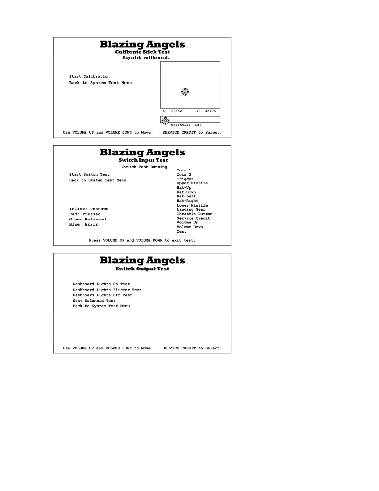
Chapter 4 — Operator Menu and Game Setup
This screen lets you calibrate the
joystick and throttle. Highlight
Start Calibration, press
SERV/SEL, and then follow the
onscreen prompts.
See page 26 for detailed
calibration instructions.
This menu lets you test all of the
switches on the player controls
and operator buttons. The name
of each switch is displayed in
yellow first, and then changes to
red when the switch is activated
and green when released. Blue
text indicates the switch is stuck
in the ON position.
This menu lets you test the
dashboard instrument panel
lights that flicker when the
player takes damage, and the
force-feedback seat solenoid.
Blazing Angels Operation and Service Manual
Page 16 of 64 040-0168-01 Rev. B 3/14/2008
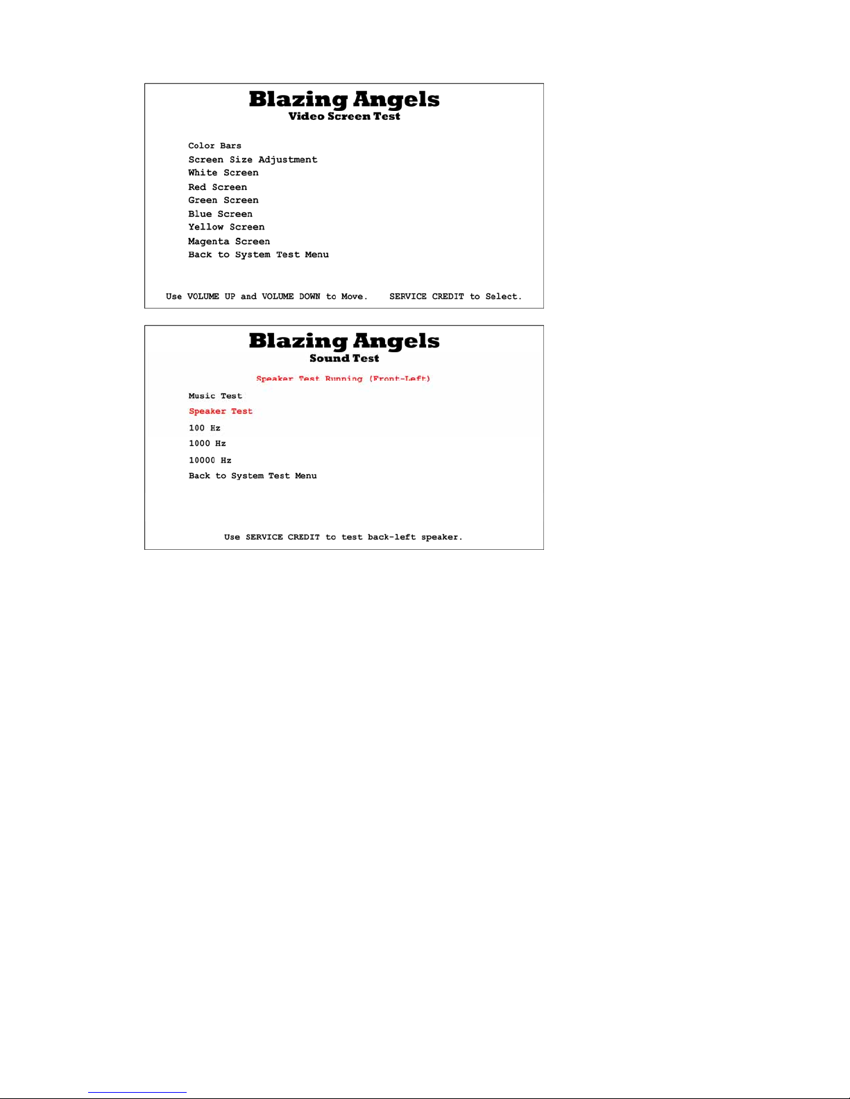
Chapter 4 — Operator Menu and Game Setup
This menu lets you open a series
of Video Test Screens that you
can use to adjust the image using
the monitor remote control
board. Press SERV/SEL to exit
from any Video Test Screen.
This menu lets you test cabinet
audio.
Music Test plays music so you
can hear overall audio
performance.
Speaker Test plays sound from
each speaker, one by one.
The remaining items emit a test
tone at the indicated frequency.
This lets you confirm that the
system is playing the full range
of sound frequencies.
©2007 Global VR, Inc.
040-0168-01 Rev. B 3/14/2008 Page 17 of 64
Chapter 4 — Operator Menu and Game Setup
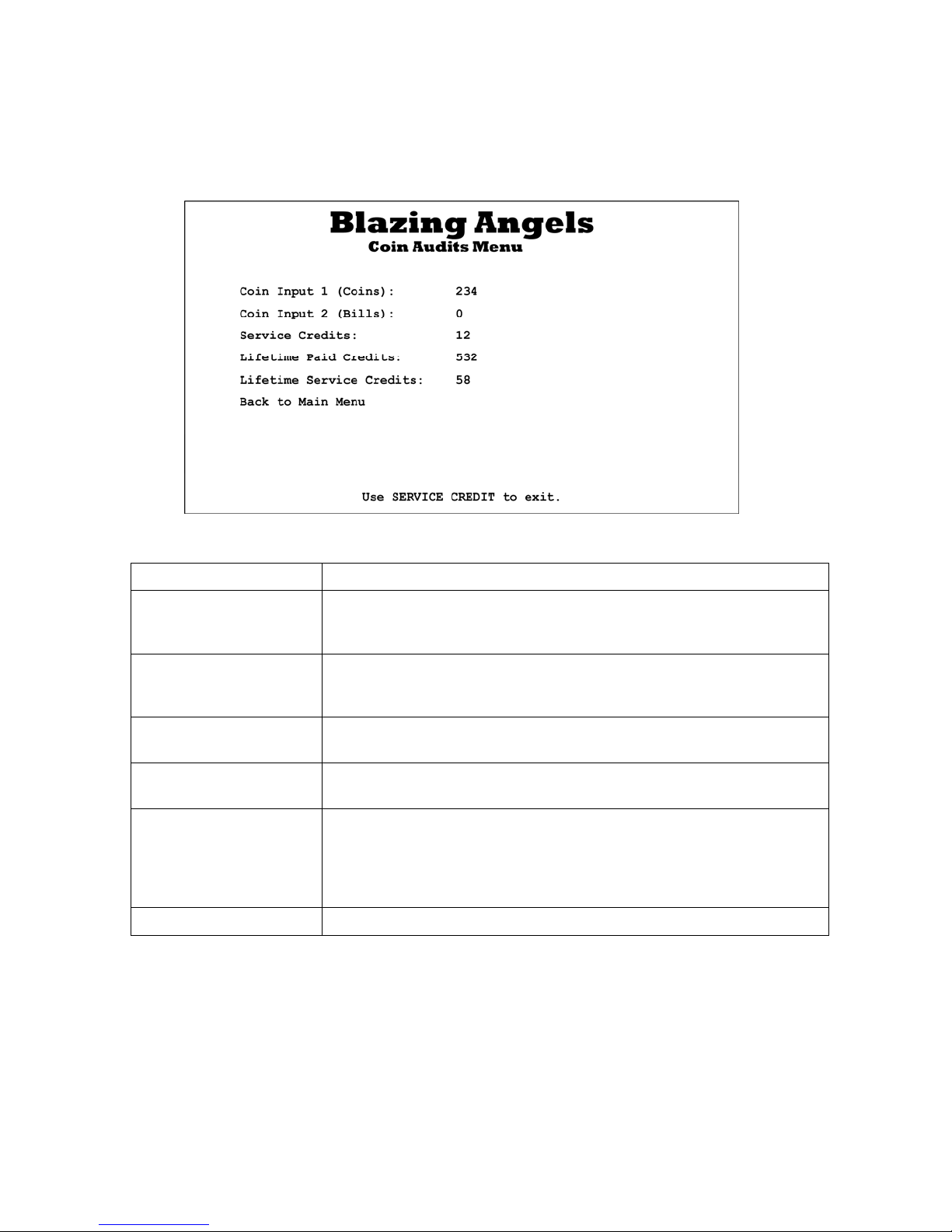
Coin Audits Menu
This screen displays earnings stats. To clear these audits, except for Lifetime totals, select Reset
Coin and Game Audits from the Reset Menu.
Figure 8. Coin Audits Menu
Menu Item Description
Coin Input 1 (Coins) Displays total coins from Coin Input 1, normally used for coin mechs,
since the last time Reset Coin and Game Audits was selected from
the Reset Menu.
Coin Input 2 (Bills) Displays total coins from Coin Input 1, normally used for the bill
validator, since the last time Reset Coin and Game Audits was
selected from the Reset Menu.
Service Credits Displays available service credits. Clear service credits by selecting
Reset Available Total Credits from the Reset menu.
Lifetime Paid Credits Displays lifetime paid credits inserted since the software was installed.
This number is never reset unless you reinstall the software.
Lifetime Service Credits Displays lifetime service credits used since the software was installed.
This number is never reset unless you reinstall the software. Service
Credits are not counted if they are cleared and not used.
Note: The Lifetime Service Credits starts at 58 when software is
installed. Subtract 58 to get your actual total.
Back to Main Menu Returns to the Operator Main Menu.
Blazing Angels Operation and Service Manual
Page 18 of 64 040-0168-01 Rev. B 3/14/2008
Chapter 4 — Operator Menu and Game Setup
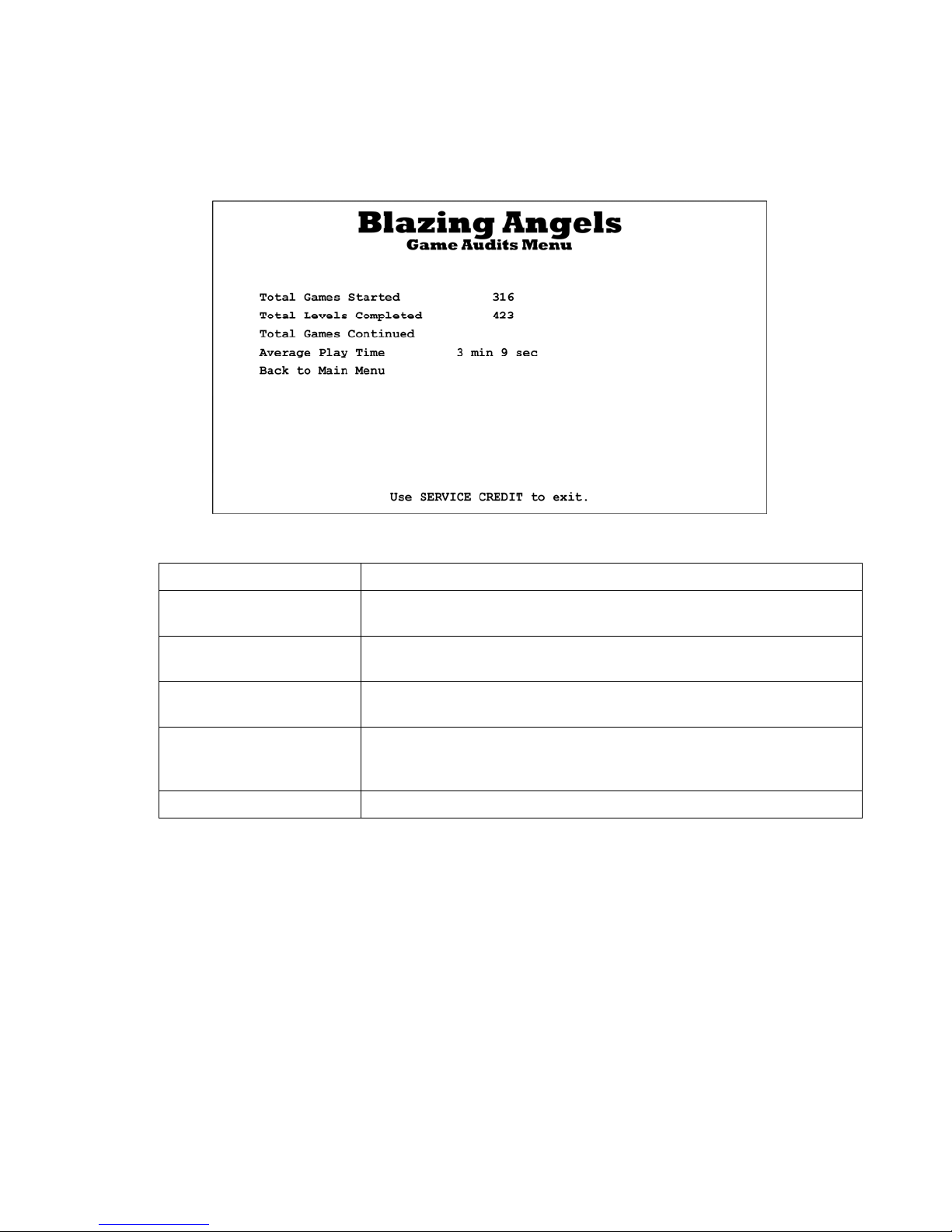
Game Audits Menu
This screen displays stats about game play. To clear these audits, select Reset Coin and Game
Audits from the Reset Menu.
Figure 9. Game Audits Menu
Menu Item Description
Total Games Started Displays the total number of games started since the last time Reset
Coin and Game Audits was selected from the Reset Menu.
Total Levels Completed Displays the total levels completed since the last time Reset Coin
and Game Audit s was selected from the Reset Menu.
Total Games Continued Displays the number of games continued since the last time Reset
Coin and Game Audits was selected from the Reset Menu.
Average Play Time Displays the average time a player plays, including continues, since
the last time Reset Coin and Game Audits was selected from the
Reset Menu.
Back to Main Menu Returns to the Operator Main Menu.
©2007 Global VR, Inc.
040-0168-01 Rev. B 3/14/2008 Page 19 of 64
Chapter 4 — Operator Menu and Game Setup
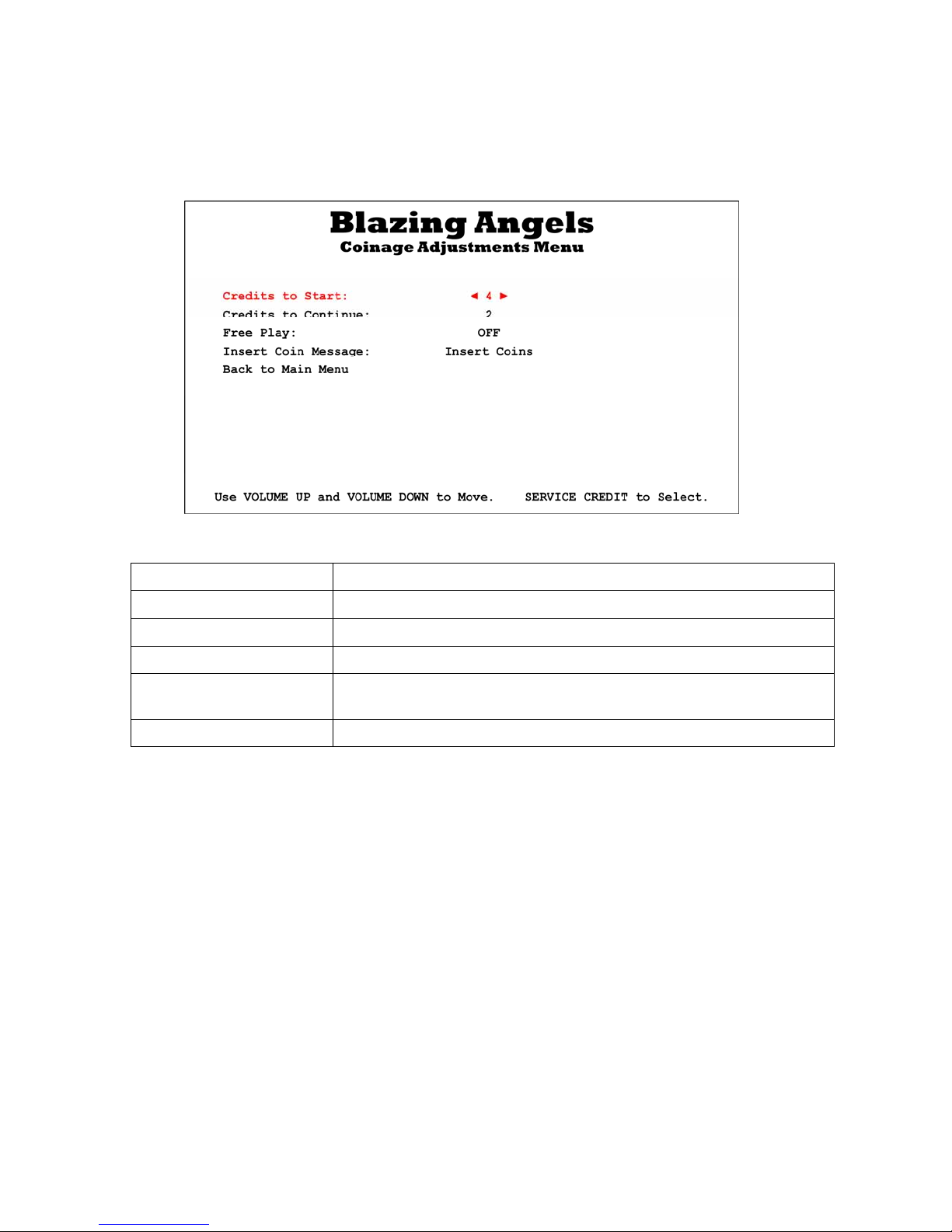
Coinage Adjustments Menu
This screen lets you set pricing, turn free play on or off, and change the message displayed in
Attract Mode telling players to Insert Coins.
Figure 10. Coinage Adjustments Menu
Menu Item Description
Credits to Start Sets the number of credits to start a game.
Credits to Continue Sets the number of credits to continue a game.
Free Play Turns Free Play ON or OFF.
Insert Coin message Selects the message displayed during the Attract Loop. Options are:
Insert Coins, Insert Card, Insert Credits, or Swipe Card.
Back to Main Menu Returns to the Operator Main Menu.
Blazing Angels Operation and Service Manual
Page 20 of 64 040-0168-01 Rev. B 3/14/2008
 Loading...