

Global Traffic Technologies Opticom Installation Manual

Installation Manual April 2011
Opticom
GPS System
Vehicle Equipment

Vehicle Equipment Installation Instructions i
Table of Contents
1 About This Manual ............................................................................................................................................ 1
1.1 Purpose of Manual .................................................................................................................................... 1
1.2 Manual Conventions ................................................................................................................................ 1
1.3 Related Publications ................................................................................................................................. 1
1.4 Manual Organization ............................................................................................................................... 1
2 Safety Information ............................................................................................................................................ 2
2.1 Intended Use ............................................................................................................................................. 2
2.2 Technical Support ..................................................................................................................................... 2
2.3 Safety Messages and Safety Labels .......................................................................................................... 2
2.3.1 Safety Message Format ..................................................................................................................... 2
2.3.2 Safety Label Format........................................................................................................................... 3
2.4 Safety Messages Contained in this Manual ............................................................................................ 4
2.5 Label Locations ......................................................................................................................................... 6
2.6 Safety Considerations ............................................................................................................................... 7
2.6.1 Personal Safety Equipment and Clothing ....................................................................................... 7
2.6.2 Electric Shock .................................................................................................................................... 7
2.6.3 Explosion ............................................................................................................................................ 7
2.6.4 Chemical Burns ................................................................................................................................. 7
2.7 Disposal of Device .................................................................................................................................... 7
2.8 FCC Statement ........................................................................................................................................... 7
3 Description ........................................................................................................................................................ 8
3.1 Opticom™ GPS System ............................................................................................................................ 8
3.2 Vehicle Equipment .................................................................................................................................... 9
3.3 Parts List ................................................................................................................................................... 10
4 Features ............................................................................................................................................................ 10
5 Installation ....................................................................................................................................................... 11
5.1 Vehicle Radio/GPS Unit Installation ..................................................................................................... 12
5.2 Model 1050 Radio/GPS antenna installation ....................................................................................... 13
5.3 Model 794HM, Model 794TM .............................................................................................................. 14
5.4 Radio/GPS Unit Cable Terminations ..................................................................................................... 15
5.5 Vehicle Control Unit Installation ........................................................................................................... 16
5.5.1 Turn Signal Sensing Connections .................................................................................................. 19
5.5.2 Additional Vehicle Connections ................................................................................................... 19
5.5.3 Low Priority ..................................................................................................................................... 20
5.5.4 Probe Priority/GPS always out ....................................................................................................... 20
6 Checkout .......................................................................................................................................................... 21
6.1 Configuration Setup and Checkout ....................................................................................................... 21
6.2 Input Verification .................................................................................................................................... 21
6.3 Performance Tests ................................................................................................................................... 22
7 Troubleshooting .............................................................................................................................................. 24
8 Maintenance .................................................................................................................................................... 26
9 GPS Output Function ..................................................................................................................................... 26

Vehicle Equipment Installation Instructions 1
1 About This Manual
1.1 Purpose of Manual
This manual provides step-by-step instructions for
installing the Global Traffic Technologies
Opticom™ GPS System* vehicle equipment. It is
intended for use by installers, maintenance
personnel, and others who are responsible for the
installation and maintenance of the system.
1.2 Manual Conventions
The conventions listed in Table 1-1 help to
make this manual easier to use by presenting a
uniform approach to the descriptions, phrases,
and nomenclature.
1.3 Related Publications
Opticom™ GPS System Intersection Equipment
Installation Instructions.
Opticom™ GPS System Operation Manual.
1.4 Manual Organization
This manual is divided into eight sections.
Section 1. About This Manual
Contains information about the organization and
content of this manual.
Table 1-1. Manual Conventions
Section 2. Safety Information
Contains important information about the safety
messages, safety labels, safety precautions, and
procedures for installation of this device.
Section 3. Description
Briefly describes the vehicle equipment and
related system components.
Section 4. Features
Describes important features and
characteristics of the vehicle equipment.
Section 5. Installation
Contains step-by-step installation instructions.
Section 6. Checkout
Contains information on how to check out
and test the installed system.
Section 7. Troubleshooting
Contains problem solutions to troubleshoot
the installed system.
Section 8. Maintenance
Contains information and recommendations to
ensure reliable system operation.
Element Convention Example
Names First or formal reference: initial
caps
Subsequent use or informal
reference: lowercase
Feature names Initial caps the Disable feature
Switch position Uppercase the OFF position
*The method of using the components of the Opticom GPS system may be covered by one or more of US
Patent Numbers 5539398, 5926113, 5986575, 6243026.
Opticom™ GPS System Vehicle
Radio/GPS Unit
radio/GPS unit
Vehicle Equipment Installation Instructions 2
2 Safety Information
We provide important safety information and
warnings to assist you in understanding and
avoiding potential harm to yourself, and
possible damage to equipment, during the
installation of Opticom™ GPS System
equipment. Although we have included many
potential hazards you may encounter during
the installation of this equipment, we cannot
predict all of the possible hazards and this list
should not be a substitute for your judgment
and experience.
Please read, understand, and follow all safety
information contained in these instructions
before installing the system equipment. Save
this installation manual and keep it near the
equipment.
If you are unsure about any part of this
installation or of the potential hazards
discussed, please contact your supervisor
immediately.
2.3.1 Safety Message Format
Safety messages are designed to alert you to
potential hazards that can cause personal injury
to you or others. They can also indicate the
possibility of property damage.
Each safety message box contains a safety alert
symbol (
WARNING, CAUTION, or IMPORTANT NOTE;
and a safety message.
The signal words and symbols, and their
meanings, are shown below:
The safety message is in this box.
WARNING indicates a potentially hazardous
situation, which, if not avoided, could result in
death or serious injury.
); one of three signal words:
WARNING
2.1 Intended Use
The system is intended to assist authorized priority
vehicles through signalized intersections by
providing temporary right-of-way through vehicle
operator interface to the system and through the
use of common traffic controller functions. GTT
has not evaluated this product for use in any other
application.
2.2 Technical Support
If you have questions about the system, its use,
or operation, please contact your dealer or call
the GTT Technical Service department at 1800-258-4610.
2.3 Safety Messages and Safety Labels
We include safety messages and safety labels
in this manual to help you protect your safety
and the safety of others. This section contains
important information to help you recognize
and understand these safety messages.
CAUTION
The safety message is in this box.
CAUTION indicates a potentially hazardous
situation, which, if not avoided, may result in
minor or moderate injury.
IMPORTANT NOTE
The safety message is in this box.
IMPORTANT NOTE indicates a potentially
hazardous situation, which, if not avoided, may
result in property damage.
In addition to the symbols and words explained
above, each safety message identifies the hazard,
describes what you can and should do to avoid
the risk of exposure to the hazard, and tells the
probable consequences of not avoiding the
hazard.
Please read all messages before proceeding with
the installation.
Vehicle Equipment Installation Instructions 3
2.3.2 Safety Label Format
We include safety labels on the devices to help
you protect your safety and the safety of others.
Safety labels are designed to alert you to potential
hazards associated with a piece of equipment that
can cause personal injury to you or others. They
can also indicate the possibility of property
damage.
Please read all safety labels.
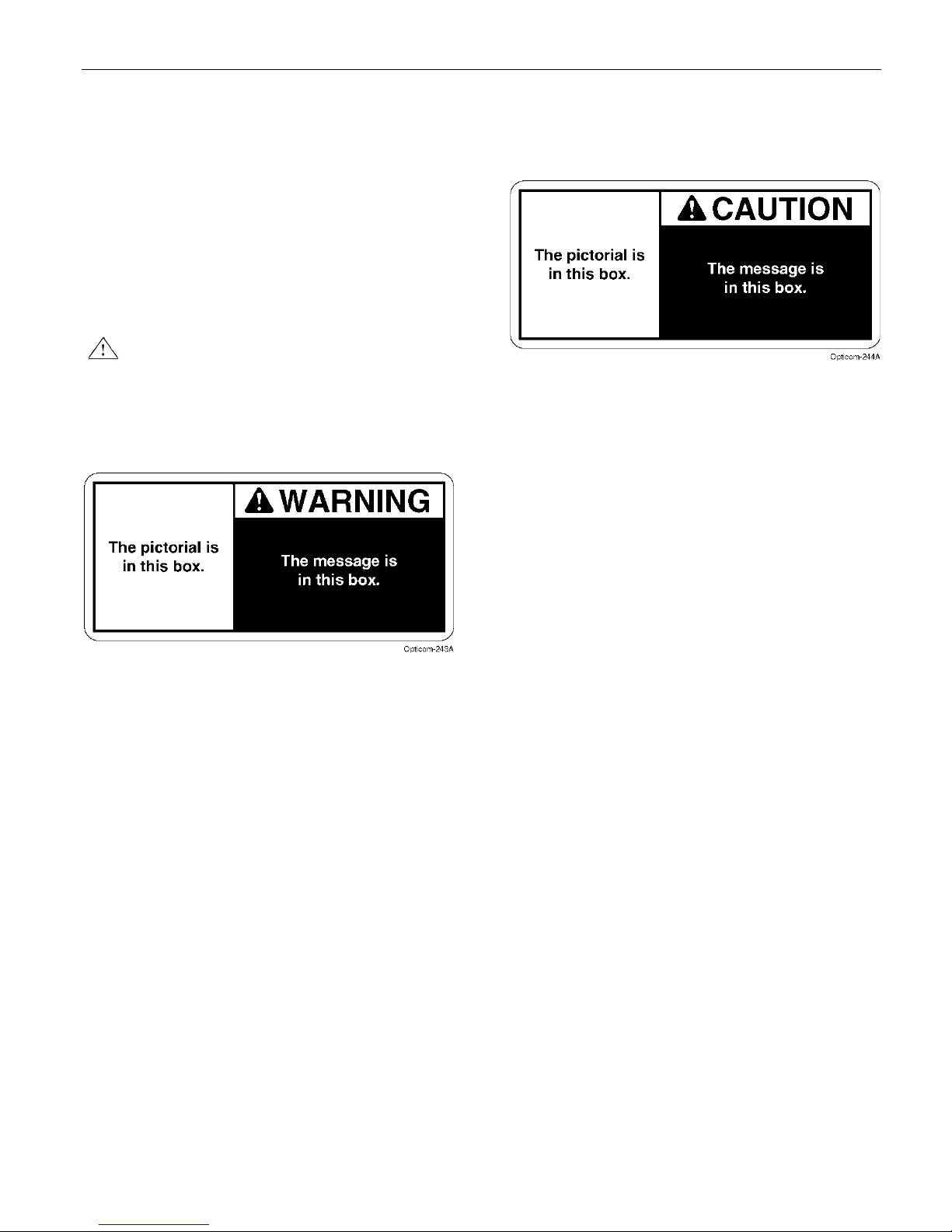
Each safety label contains a safety alert symbol
(
), one of two signal words: WARNING or
CAUTION, a pictorial showing the nature of the
hazard, and a safety message.
The signal words and symbols, and their
meanings, are shown below:
WARNING indicates a potentially hazardous
situation, which, if not avoided, could result in
death or serious injury.
CAUTION indicates a potentially hazardous
situation, which, if not avoided, may result in
minor or moderate injury.
We consider safety labels to be an important part
of all devices and they should be replaced
immediately if they become hard to read.
If any of the safety labels are missing or cannot be
read, please contact your dealer or the GTT
Repair department for a replacement.
Vehicle Equipment Installation Instructions 4
2.4 Safety Messages Contained in this
Manual
The following safety messages appear in this
manual:
WARNING
This equipment has been approved for mobile
applications where the equipment should be
used at distances greater than 20 cm from the
human body (with the exception of hands,
wrists, feet and ankles). Operation at distances
less than 20cm is strictly prohibited.
Note: This equipment has been tested and
found to comply with the limits for a Class A
digital device, pursuant to part 15 of the FCC
Rules. These limits are designed to provide
reasonable protection against harmful
interference when the equipment is operated in
a commercial environment. This equipment
generates, uses, and can radiate radio
frequency energy and, if not installed and used
in accordance with the instruction manual,
may cause harmful interference to radio
communications. Operation of this equipment
in a residential area is likely to cause harmful
interference in which case the user will be
required to correct the interference at his own
expense.
NOTICE
This Class A digital apparatus complies
with Canadian ICES-003.
Cet appareil numérique de la classe A
conforme à la norme NMB-003 du
Canada.
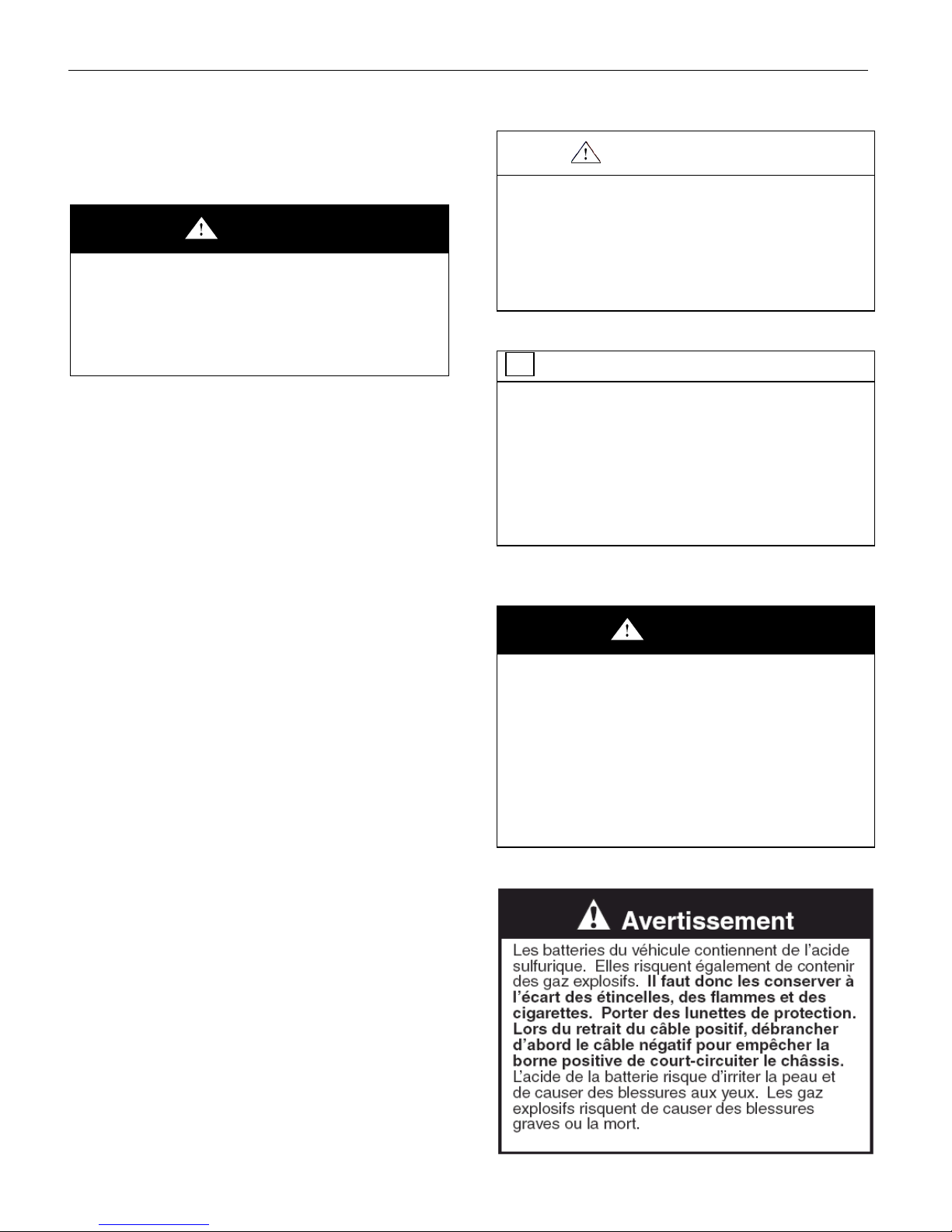
IMPORTANT NOTE
Modifying the radio/GPS unit may seriously
damage the equipment and void the warranty.
Do not attempt to modify the radio/GPS
circuitry in any way. Modifying the radio
and/or antenna in any way may cause the radio
to violate FCC/IC requirements.
REMARQUE IMPORTANTE
La modification du système radio/GPS risque
d’endommager sérieusement le matériel et
d’annuler la garantie. Ne pas tenter de modifier
les circuits du système radio/GPS de quelque
façon que ce soit. En modifiant le système radio
et/ou l’antenne de quelque façon que ce soit, la
radio risque de ne plus répondre aux exigences
de la FCC/IC.
WARNING
Vehicle batteries contain sulfuric acid and
may contain explosive gases. Keep sparks,
flames, and cigarettes away. Wear eye
protection. Disconnect the negative cable
first to prevent shorting the positive terminal
to the chassis when removing the positive
cable. Battery acid may cause skin irritation
and eye injury. Explosive gases may cause
severe injury or death.
Vehicle Equipment Installation Instructions 5
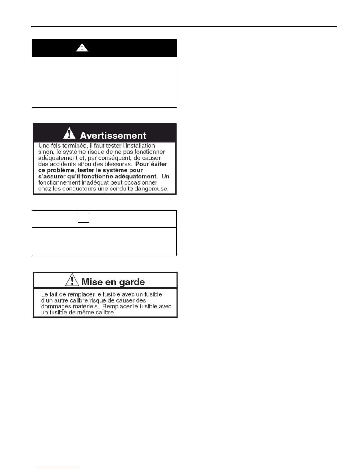
WARNING
A completed installation that is not tested may
result in improper system operation, which may
result in accidents and/or injuries. To avoid this
problem, test the system to verify proper
operation. Improper system operation may
result in unsafe driver action.
CAUTION
Failure to replace the fuse size as marked may
cause property damage. Replace fuse size as
marked.
Vehicle Equipment Installation Instructions 6
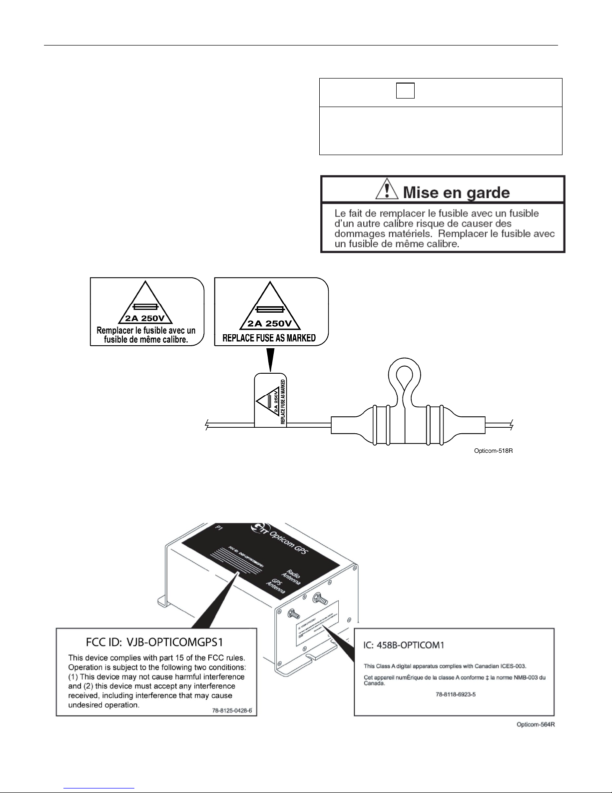
2.5 Label Locations
There is one safety label, one FCC label and
one IC label on the Opticom™ GPS System
vehicle equipment. If a label is missing or
cannot be read, please contact your dealer or
the GTT Repair department for a replacement.
See Figures 2-1 and 2-2 for label locations.
CAUTION
Failure to replace the fuse size as marked may
cause property damage. Replace fuse size as
marked.
Figure 2-1. Vehicle Equipment Fuse Safety Label Location
Figure 2-2. FCC, IC Label Location

Vehicle Equipment Installation Instructions 7
2.6 Safety Considerations
Please consider the following safety issues before
beginning the installation of the Opticom™ GPS
System vehicle equipment.
Although we have compiled this list of common
safety considerations, it should not be considered
as complete. It is not intended to take the place
of your good judgment, training, and experience.
2.6.1 Personal Safety Equipment and
Clothing
Personal safety equipment and clothing including
high visibility vests, hard hats, gloves, electrical
shock or electrocution protection clothing and
equipment, safety shoes, safety glasses, face
shields, goggles, and hearing protection devices
are just some of the items available to you.
Choose the right equipment for the job. If you
are unsure of which safety equipment is
recommended or appropriate for the job, ask
your supervisor or foreman.
2.6.3 Explosion
Common automotive-type batteries produce an
explosive gas under some conditions. This gas
may easily be ignited by a spark or flame as you
work on the vehicle. To reduce the risk of
explosion, disconnect the battery, work in a
well ventilated area, avoid the use of devices
that create sparks or use open flames, and use
the appropriate personal safety equipment and
clothing.
If you are unsure of which techniques,
procedures, and protective equipment are
recommended or appropriate for the job, ask your
supervisor or foreman.
2.6.4 Chemical Burns
Common automotive-type batteries contain strong
acid that can cause personal injury if you come in
contact with the acid. To reduce exposure to the
risk of chemical burns, wear appropriate
protective clothing and handle the battery with
care.
2.6.2 Electric Shock
As a trained installer of electrical equipment you
are aware of the dangers associated with
installation of electrical devices. Always be sure
that the power to the equipment, and all associated
equipment, is turned off and the vehicle battery is
disconnected. Use the equipment, techniques,
and procedures that you learned during your
training or apprenticeship or other electrical
industry recognized safety procedures.
If you are unsure of which techniques,
procedures, and protective equipment are
recommended or appropriate for the job, ask your
supervisor or foreman.
If you are unsure of which techniques,
procedures, and protective equipment are
recommended or appropriate for the job, ask your
supervisor or foreman.
2.7 Disposal of Device
Please dispose of the device in accordance
with all local, state, and federal laws and
regulations.
2.8 FCC Statement
This equipment has been tested and found to
comply within the limits for a Class A digital
device, pursuant to part 15 of the FCC rules.
These limits are designed to provide reasonable
protection against harmful interferences when
the equipment is operated in a commercial
environment. This equipment generates uses
and can radiate radio frequency energy and, if
not installed and used in accordance with the
instruction manual, may cause harmful
interference to radio communications. If
operation of this equipment in a residential area
causes harmful interference, the user is required
to correct the interference at their own expense.
See Figure 2-2.

Vehicle Equipment Installation Instructions 8
3 Description
This section provides a general description of the
Opticom™ GPS system and a detailed description
of the vehicle equipment.
3.1 Opticom™ GPS System
The Opticom GPS system assists authorized
priority vehicles through signalized
intersections by providing temporary right-ofway through the use of common traffic
controller functions.
The Opticom GPS system consists of the
following matched components:
Vehicle Equipment —
Radio/GPS unit containing a GPS receiver and
a 2.4 GHz transceiver
Radio/GPS antenna
Control unit
Intersection Equipment —
Radio/GPS unit containing a GPS receiver
with antenna and a 2.4 GHz transceiver with
antenna
Or Radio/GPS unit containing a GPS receiver
and a 2.4 GHz spread spectrum transceiver
with a separate Radio/GPS antenna
Phase Selector
Card Rack/Input File
Auxiliary Interface Panel
The vehicle equipment is mounted on the priority
vehicle. Its GPS receiver acquires position
information from the constellation of GPS
satellites. This information is used to compute the
location, speed, and heading of the vehicle. This
information, along with a priority request and the
state of the vehicle’s turn signal, is broadcast using
the 2.4 GHz transceiver.
The intersection equipment receives the radio
transmission from the vehicle equipment. The
intersection equipment then compares the
information being received from the vehicle to
the parameters stored in the intersection
equipment’s memory. If the vehicle is heading
toward the intersection in a predefined
approach corridor, is requesting preemption and
has met all other programmed parameters, the
corresponding phase selector output is
activated. This output is connected to the traffic
controller preemption input. When activated,
the controller cycles to grant a green light to the
requesting vehicle or holds the green allowing
the vehicle to pass through the intersection.
The card rack/input file provides the power and
logic wiring for the phase selector, which plugs
directly into a slot in the unit.
The auxiliary interface panel provides additional
connections for monitoring green phases and
also provides additional priority control outputs.
The green sense harness can be used to provide
additional connections for monitoring green
phases when the auxiliary interface panel is not
required.
Auxiliary Harness
 Loading...