

global thermoelectric 8550 Operating Manual

8550
Thermoelectric
Generator
Operating Manual
23658 Rev. 4
Global Thermoelectric
Bay 9, 3700 - 78 AVE., S.E.
Calgary , Albert a, Canada
T2C 2L8
Phone: 1-403-236-5556
Fax: 1-403-236-5575
EMAIL: service@globalte.com


OCTOBER 19, 1992
GLOBAL THERMOELECTRIC
MODEL CP8550 GENERATOR
WARNING:DO NOT ALLOW CURRENT TO CATHODIC PROTECTION LOAD
TO EXCEED 30 AMPS.
THE MODEL CP8550 GENERATOR IS NOT RATED TO SUPPLY MORE THAN 30
AMPS OF CURRENT TO THE LOAD. IF TOTAL CIRCUIT RESISTANCE IS LESS
THAN 0.5 OHMS THEN THE 1000 WATT VARIABLE RESISTOR IN THE CP BOX
SHOULD BE WIRED IN SERIES WITH THE CIRCUIT AND ADJUSTED SO THAT
CURRENT DOES NOT EXCEED 30 AMPS.
FOR FURTHER INFORMATION PLEASE CONTACTTHE GLOBALCUSTOMER SERVICE DEPARTMENT AT THE NUMBER SHOWN BELOW.
GLOBAL THERMOELECTRIC
BAY 9, 3700 - 78 AVE. S.E.
CALGARY, ALBERTA, CANADA
T2C 2L8
PHONE: 1-403-236-5556
FAX: 1-403-236-5575
COPYRIGHT (C) 1991 GLOBAL THERMOELECTRIC


TABLE OF CONTENTS
1 General Information . . . . . . . . . . . . . . . . . . . . . . . . . . . . . . . . . . . . . . . . . . . . . . . . . . . . . . .1-1
1.1 Manual Identification . . . . . . . . . . . . . . . . . . . . . . . . . . . . . . . . . . . . . . . . . . . . . . . . . . .1-1
1.2 Definition of Terms . . . . . . . . . . . . . . . . . . . . . . . . . . . . . . . . . . . . . . . . . . . . . . . . . . . . .1-1
1.3 Theory of Operation . . . . . . . . . . . . . . . . . . . . . . . . . . . . . . . . . . . . . . . . . . . . . . . . . . . .1-2
1.4 Physical Description . . . . . . . . . . . . . . . . . . . . . . . . . . . . . . . . . . . . . . . . . . . . . . . . . . . .1-3
1.5 Electrical Output Characteristics . . . . . . . . . . . . . . . . . . . . . . . . . . . . . . . . . . . . . . . . . .1-4
1.6 Fuel Information . . . . . . . . . . . . . . . . . . . . . . . . . . . . . . . . . . . . . . . . . . . . . . . . . . . . . . .1-6
2 Installation and Operation . . . . . . . . . . . . . . . . . . . . . . . . . . . . . . . . . . . . . . . . . . . . . . . . . .2-1
2.1 Unpacking and Mounting . . . . . . . . . . . . . . . . . . . . . . . . . . . . . . . . . . . . . . . . . . . . . . . .2-1
2.2 Data Plate Information . . . . . . . . . . . . . . . . . . . . . . . . . . . . . . . . . . . . . . . . . . . . . . . . . .2-2
2.3 Fuel Supply . . . . . . . . . . . . . . . . . . . . . . . . . . . . . . . . . . . . . . . . . . . . . . . . . . . . . . . . . .2-3
2.4 Ignition and Start Procedure . . . . . . . . . . . . . . . . . . . . . . . . . . . . . . . . . . . . . . . . . . . . . .2-4
2.5 Heat Up and Power Adjustment . . . . . . . . . . . . . . . . . . . . . . . . . . . . . . . . . . . . . . . . . . .2-8
2.6 Applying Customer Load . . . . . . . . . . . . . . . . . . . . . . . . . . . . . . . . . . . . . . . . . . . . . . .2-11
2.7 System Performance Log . . . . . . . . . . . . . . . . . . . . . . . . . . . . . . . . . . . . . . . . . . . . . . .2-11
3 Service and Maintenance . . . . . . . . . . . . . . . . . . . . . . . . . . . . . . . . . . . . . . . . . . . . . . . . . .3-1
3.1 Suggested Periodic Maintenance . . . . . . . . . . . . . . . . . . . . . . . . . . . . . . . . . . . . . . . . .3-1
3.2 Power Check . . . . . . . . . . . . . . . . . . . . . . . . . . . . . . . . . . . . . . . . . . . . . . . . . . . . . . . . .3-3
3.3 Fuel System . . . . . . . . . . . . . . . . . . . . . . . . . . . . . . . . . . . . . . . . . . . . . . . . . . . . . . . . . .3-3
3.4 Burner System . . . . . . . . . . . . . . . . . . . . . . . . . . . . . . . . . . . . . . . . . . . . . . . . . . . . . . . .3-5
3.5 Cooling System . . . . . . . . . . . . . . . . . . . . . . . . . . . . . . . . . . . . . . . . . . . . . . . . . . . . . . .3-7
3.6 Spark Ignition (SI) . . . . . . . . . . . . . . . . . . . . . . . . . . . . . . . . . . . . . . . . . . . . . . . . . . . . . .3-8
3.7 Automatic Shut-Off (SO) . . . . . . . . . . . . . . . . . . . . . . . . . . . . . . . . . . . . . . . . . . . . . . . .3-11
3.8 Power Unit Testing . . . . . . . . . . . . . . . . . . . . . . . . . . . . . . . . . . . . . . . . . . . . . . . . . . . .3-12
3.9 Over Temperature Shutdown System . . . . . . . . . . . . . . . . . . . . . . . . . . . . . . . . . . . . .3-14
3.10 Trouble Shooting Guide . . . . . . . . . . . . . . . . . . . . . . . . . . . . . . . . . . . . . . . . . . . . . . . .3-16
3.11 8550 TEG Parts List . . . . . . . . . . . . . . . . . . . . . . . . . . . . . . . . . . . . . . . . . . . . . . . . . . .3-18
3.12 Fuel System Parts List . . . . . . . . . . . . . . . . . . . . . . . . . . . . . . . . . . . . . . . . . . . . . . . . .3-21
4 APPENDIX . . . . . . . . . . . . . . . . . . . . . . . . . . . . . . . . . . . . . . . . . . . . . . . . . . . . . . . . . . . . . . .4-1
4.1 Gas Specifications . . . . . . . . . . . . . . . . . . . . . . . . . . . . . . . . . . . . . . . . . . . . . . . . . . . . .4-1
4.2 8550 Performance Log . . . . . . . . . . . . . . . . . . . . . . . . . . . . . . . . . . . . . . . . . . . . . . . . . .4-3

LIST OF ILLUSTRATIONS
Figure 1 Design Illustration . . . . . . . . . . . . . . . . . . . . . . . . . . . . . . . . . . . . . . . . . . . . . . .1-2
Figure 2 Model 8550 Dimensions . . . . . . . . . . . . . . . . . . . . . . . . . . . . . . . . . . . . . . . . . .1-4
Figure 3 Power Unit Electrical Output Characteristics (without Power Conditioner) . . .1-5
Figure 4 Power as a Function of Ambient Temperature . . . . . . . . . . . . . . . . . . . . . . . . .1-6
Figure 5 TEG Mounting . . . . . . . . . . . . . . . . . . . . . . . . . . . . . . . . . . . . . . . . . . . . . . . . . .2-2
Figure 6 Altitude Adjustment . . . . . . . . . . . . . . . . . . . . . . . . . . . . . . . . . . . . . . . . . . . . . .2-4
Figure 7 Applying Thread Sealant . . . . . . . . . . . . . . . . . . . . . . . . . . . . . . . . . . . . . . . . .2-4
Figure 8 Wiring Diagram, 8550 TEG . . . . . . . . . . . . . . . . . . . . . . . . . . . . . . . . . . . . . . . .2-5
Figure 9 Fuel System Components, SI and SO . . . . . . . . . . . . . . . . . . . . . . . . . . . . . . .2-7
Figure 10 Power Calculation . . . . . . . . . . . . . . . . . . . . . . . . . . . . . . . . . . . . . . . . . . . . . . .2-8
Figure 11 Air Shutter Adjustment . . . . . . . . . . . . . . . . . . . . . . . . . . . . . . . . . . . . . . . . . .2-10
Figure 12 Fuel System Components, SI and SO . . . . . . . . . . . . . . . . . . . . . . . . . . . . . . .3-4
Figure 13 Orifice Assembly Removal . . . . . . . . . . . . . . . . . . . . . . . . . . . . . . . . . . . . . . . .3-5
Figure 14 Burner System Components . . . . . . . . . . . . . . . . . . . . . . . . . . . . . . . . . . . . . . .3-6
Figure 15 Spark Ignition System Wiring . . . . . . . . . . . . . . . . . . . . . . . . . . . . . . . . . . . . . .3-8
Figure 16 Spark Ignition Components . . . . . . . . . . . . . . . . . . . . . . . . . . . . . . . . . . . . . . . .3-9
Figure 17 Automatic Shut-Off Components . . . . . . . . . . . . . . . . . . . . . . . . . . . . . . . . . .3-12
Figure 18 Over Temperature Shut Down System . . . . . . . . . . . . . . . . . . . . . . . . . . . . . .3-15
Figure 19 8550 TEG Parts List, Sheet 1 . . . . . . . . . . . . . . . . . . . . . . . . . . . . . . . . . . . . .3-18
Figure 20 8550 TEG Parts List, Sheet 2 . . . . . . . . . . . . . . . . . . . . . . . . . . . . . . . . . . . . .3-19
Figure 21 Fuel System Parts List, 8550 TEG . . . . . . . . . . . . . . . . . . . . . . . . . . . . . . . . .3-21

Global Thermoelectric 1-1
23658 Rev. 4
1 GENERAL INFORMATION
1.1 Manual Identification
1.1.1 This manual provides installation, operation and maintenance instructions for the Global
Model 8550 Thermoelectric Generator. The generator must be used in conjunction with a
Power Conditioner. The manual for the operation of this Power Conditioner is included following this manual. In addition, instructions for the operation of the Cathodic Protection
Interface System is also included.
1.2 Definition of Terms
1.2.1 To correctly use this manual the reader must interpret the meaning of the following terms as
herein defined:
Thermoelectric Generator. A device that produces electrical power through the direct conversion of heat energy to electrical energy including its burner and fuel system.
Power Unit. The hermetically sealed portion of the generator that contains the thermoelectric materials.
TEG. AThermoelectric Generator.
Matched Load. A condition of load where the load voltage of the generator is one half of the
open circuit voltage.
Optimum Load. A condition of load where the power output of the generator is maximized.
Power Conditioner. Abroad term used to describe an electronic device attached to the gen-
erator that converts, adjusts, limits or otherwise conditions the output power.
Converter-Limiter (C/L). A specific electronic device attached between the generator and
load that converts one level of DC voltage to another, and limits the voltage level.
Converter. A specific electronic device attached between the generator and load that con-
verts one level of DC voltage to another.
Limiter. Aspecific electronic device attached between the generator and load that limits the
voltage level.
Heat Pipe. A hermetically sealed fluid filled heat transfer device and its associated cooling
fins used to cool the cold junctions of the power unit.
Rated Power. The power which the TEG's power will produce at standard temperature and
voltage.
Set Power. The power level to which the power unit is set up at non-standard temperatures
in order that it will produce Rated Power when the temperature returns to standard.
Global Thermoelectric 1-2
23658 Rev. 4
1.3 Theory of Operation
1.3.1 A TEG produces electrical power through the direct conversion of heat energy into electrical
energy. When two dissimilar materials which are joined together and are heated at one end
(a thermocouple) a voltage will exist across the cooler end. Electrical power will be delivered
to a load placed in the circuit. This process will continue provided that the temperature difference is maintained. A TEG is a system which provides the means to maintain these conditions.
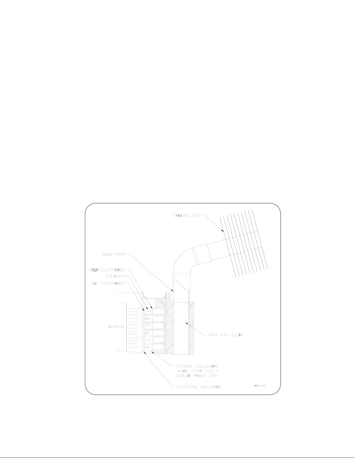
1.3.2 Figure 1 illustrates how this is accomplished in the Model 8550 TEG. A thermocouple is
formed by a P type and an N type thermoelectric element joined together electrically by a hot
junction electrode. Adjacent thermocouples are joined electrically by cold junction electrodes.
A total of 325 thermocouples, each producing 87mV, at standard conditions are connected in
series to produce 590 Watts at 28 Volts and 21 Amperes.
The hot junction of the thermocouples is maintained at a high temperature (538ºC or 1000ºF)
by a burner which operates on the gaseous fuels. The cold junction of the thermocouples is
maintained at a lower temperature (163ºC or 235ºF) by an array of heat pipes which transfer
the heat to the ambient air by natural convection. The thermocouples are contained in a hermetically sealed enclosure because they are adversely affected when exposed to air at operating temperatures. They are surrounded by thermal insulation to minimize heat loss.
Figure 1 Design Illustration

Global Thermoelectric 1-3
23658 Rev. 4
1.3.3 The cold junctions of the Model 8550 TEG are cooled by series of heat pipes. Each heat pipe
is hermetically sealed and contains a measured amount of fluid in equilibrium with its vapour.
As heat is applied to the fluid it boils and then re-condenses in the upper portion due to the
cooling effect of the cooling fins. In this way heat is transferred to the cooling fin in a very efficient manner.
1.3.4 The burner operates at moderate fuel pressures, approximately 124 kPa (18 psi) for propane
and 62 kPa (9 psi) for natural gas. The fuel gas is expanded through an orifice and then flows
through a venturi where it draws in air needed for combustion. The fuel gas flow is controlled
by a pressure regulator and adjusted by the operator to obtain the required set power.
1.3.5 Remember from electrical theory that maximum power is delivered to a load when the load
voltage is one half of the open circuit voltage of the source. This condition is called matched
load. The TEG is similar except that due to a change in the internal resistance of the power
unit with current, maximum power is delivered when the load voltage is slightly higher than
one half of the open circuit voltage.
1.3.6 The power unit must always be in a loaded condition. This is because under extended open
or high load voltage conditions the hot junction temperature may rise above the safe operating range. For this reason the power unit must always remain connected to a power conditioner which will limit the power unit voltage to less than 32.5 Volts.
1.3.7 In summary the TEG produces electrical power when a temperature difference is maintained
between the hot and cold junctions of the thermoelectric materials. The temperature difference and therefore the amount of power produced, depends on both the rate at which fuel is
supplied to the burner and the amount of cooling supplied by the ambient air. The operation
of the TEG is controlled by the fuel pressure supplied to the burner.
1.4 Physical Description
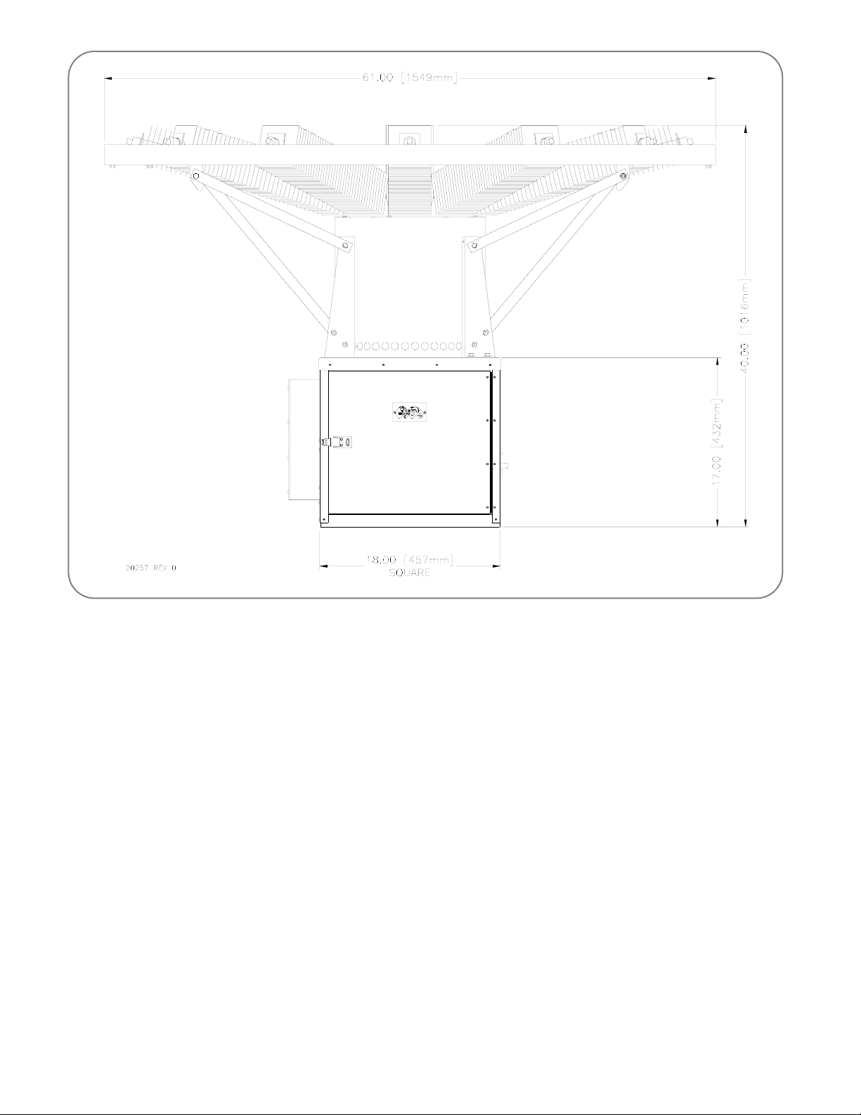
1.4.1 Figure 2 shows the Model 8550 TEG in its normal operating configuration. Physical size data
is given in Table 1.
Physical Size Data
Diameter of Top 155 cm 61 in.
Overall Height 102 cm 40 in.
Length of Lower Cabinet 46 cm 18 in.
Width of Lower Cabinet 46 cm 18 in.
Height of Lower Cabinet 44cm 17 in.
Weight (less Power Conditioner) 83 kg 183 lb
Table 1
Global Thermoelectric 1-4
23658 Rev. 4
Figure 2 Model 8550 Dimensions
1.5 Electrical Output Characteristics
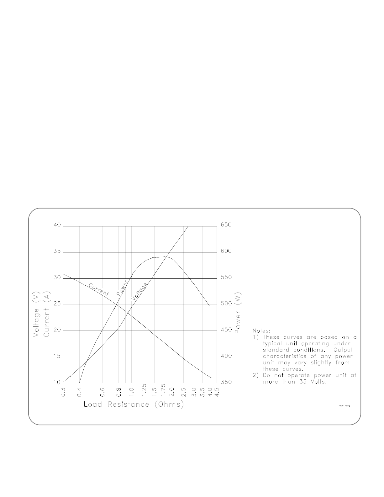
1.5.1 The typical electrical output characteristics at standard temperature of a Model 8550 power
unit without the power conditioner are shown in Figure 3. The power, current and voltage are
shown as a function of the power unit load resistance. Note that the output power curve goes
through a maximum between 1.00 and 2.00 Ohms and that rated power can only be obtained
at this point. In order to use Figure 3 consider the following example:
A load resistance of 25 Volts is required.
a) Enter the graph at 25 Volts and read horizontally across to the voltage curve.
b) Now read vertically to obtain the load resistance, available power and available current,
1.1 Ohms, 560 Watts and 22.4 Amps.
Note: That if the actual customer load requires less power, that is, has a higher resistance,
the voltage would rise. Therefore, a voltage limiting power conditioner is used to dissipate the difference between the available power and actual customer load.
Global Thermoelectric 1-5
23658 Rev. 4
Figure 3 Power Unit Electrical Output Characteristics (without Power Conditioner)
Figure 3 illustrates the importance of a power conditioner. As the load resistance increases
so does the voltage. However, the power unit will not tolerate voltages above 35 Volts, therefore the power conditioner must limit the voltage to the customer and limit the voltage of the
power unit by dissipating any excess power. Voltages outside the range of Figure 3 are
achieved by series connection of multiple TEGs or by using a DC to DC converter type power
conditioner. Consult Global Thermoelectric for the system best suited to your application.
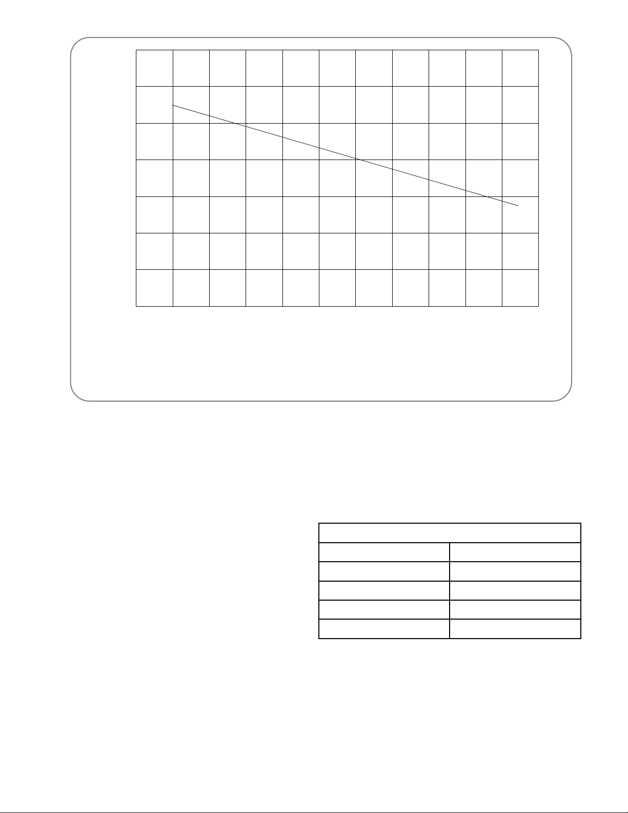
1.5.2 The available power of a Model 8550 TEG is also a function of the amount of cooling supplied
by the heat pipes. The cooling is a function of both the ambient air temperature and the wind
speed. Figure 4 shows the typical variation of output power as a function of ambient temperature for still air or low wind conditions, wind speed less than 5 km per hour (3 mph). The
effect of wind will always be to increase the cooling and therefore increase the available
power. When determining the set power, Figure 4 should be used along with the corrected
air temperature from Table 3. Whenever possible, set up and testing the generator should be
performed during periods of low wind as these readings will be more reliable than those using
the corrected air temperature method.
1.5.3 The TEG should never be operated above the curve in Figure 4, as this may result in damage to the power unit.
Global Thermoelectric 1-6
23658 Rev. 4
1.6 Fuel Information
1.6.1 The fuel consumption of a Model 8550 TEG operating at rated power under standard temperature conditions is given in Table 2. These values are subject to change without notice.
1.6.2 When operating on propane the vapour
pressure of propane at low ambient temperatures must be considered. In order
to operate reliably the fuel pressure regulator input pressure should be above
20 psig. This limits the operating temperature to above -20ºC (-4ºF). If operation below this temperature is desired a
liquid withdrawal and vaporization system must be used. Consult Global
Thermoelectric for suitable designs of such systems.
-50
-58
-40
-40
-30
-25
-20
-4
-10
-14
0
32
10
50
20
68
30
86
40
104
50
140
60°C
140°F
400
450
500
550
600
650
700
750
Set-Up Power (Watts)
at Optimum Load Condition
Ambient Temperature
Notes:
1. This curve is based on a typical power unit operating in calm air. Correction must
be made for windy conditions.
2. Do no operate power unit above this curve. Always correct air temperature for wind.
21074 rev.0
Table 2
Fuel Consumption
Propane Natural Gas
3.50 lb/hr 70 SCFH
1.59 kg/hr 2m3/hr
0.83 US gal/hr (liquid) -
3.13 liter/hr (liquid) -
Figure 4 Power as a Function of Ambient Temperature

Global Thermoelectric 1-7
23658 Rev. 4
Corrected Air Temperature for Wind
Wind
Speed
Air Temperature (ºC) (ºF)
(km/hr) -20 -15 -10 -5 0 5 10 15 20 25 30 35 40 45 50
(mile/hr) -4 5 14 23 32 41 50 59 68 77 86 95 104 113 122
0 -20 -15 -10 -5 0 5 10 15 20 25 30 35 40 45 50
0 -4 5 14 23 32 41 50 59 68 77 86 95 104 113 122
5 -27 -21 -16 -11 -6 -1 5 10 16 21 27 32 37 42 47
3.1 -17 -6 3 12 21 30 41 50 61 70 81 90 99 108 117
10 -34 -27 -21 -15 -9 -3 2 9 13 18 24 29 35 40 46
6.2 -29 -17 -6 5 16 27 36 48 55 64 75 84 95 104 115
15 -40 -32 -24 -18 -12 -6 -1 4 10 15 21 26 32 37 42
9.3 -40 -26 -11 0 10 21 30 39 50 59 70 79 90 99 109
20 -41 -35 -29 -21 -14 -8 -3 2 8 13 19 24 30 35 41
12.4 -42 -31 -20 -6 7 18 27 36 46 55 66 75 86 95 106
25 -44 -37 -31 -23 -16 -10 -5 0 6 11 17 22 28 33 38
15.5 -47 -35 -24 -9 3 14 23 32 42 52 63 72 82 91 100
30 -46 -39 -33 -25 -18 -12 -7 -1 4 9 15 20 26 31 37
18.6 -51 -38 -27 -13 0 10 19 30 39 48 59 68 79 88 99
35 -47 -40 -34 -26 -19 -13 -8 2 3 8 14 19 25 30 36
21.7 -53 -40 -29 -15 -2 9 18 28 37 46 57 66 77 86 97
40 -49 -42 -35 -22 -20 -14 -9 -3 2 7 13 18 24 29 35
24.8 -56 -44 -3 -8 -4 7 16 27 35 45 55 64 75 84 95
Table 3

Global Thermoelectric 1-8
23658 Rev. 4

Global Thermoelectric 2-1
23658 Rev. 4
2 INSTALLATION AND OPERATION
2.1 Unpacking and Mounting
2.1.1 The following tools are required in order to set up and operate the 8550 TEG:
• Avoltmeter or meters with leads and clips able to measure the following ranges:
0-30 ±0.1 V
0-30 ±0.1 mV
Customer Load Voltage
• Two small adjustable wrenches that will open to 16mm (5/8 in.).
• Amedium flat blade screwdriver.
• Afine flat blade screwdriver.
• Wire strippers or knife.
• Teflon thread sealant tape.
2.1.2 Unpack the TEG from its shipping crate. Ret ain the crate until the TEG is operational. Check
the TEG for any damage which may have occurred during shipping. Such damage should be
reported as soon as possible. Some types of damage may make the TEG inoperable.
Consult Global Thermoelectric before operating an 8550 TEG with damage.
2.1.3 Locate the installation kit containing the following:
• One spark ignitor electrode.
• 4 each 1/4 in. x 1 in. mounting bolts c/w nuts.
• Shutdown relay assembly.
Identify and locate the Power Conditioner. The Power Conditioner may have been attached
to the TEG at the factory or it may have been shipped separately, in the same or other crate,
depending on the make and model.
2.1.4 Before removing the TEG, check and re-tighten any bolts which may have come loose during
shipping. Remove the black tie wraps which clamp the ends of the heat pipe to the sup-
port ring. Failure to do this could cause the heat pipes to crack when they expand. It is recommended that lifting of the TEG be done by two or more persons. The upper ring around
the heat pipes or the frame to which this ring is mounted should be used as lifting points. If
lifting will be done by slings, they should be secured to the upper ring in at least three points
so that the TEG will not swing or rock during lifting.
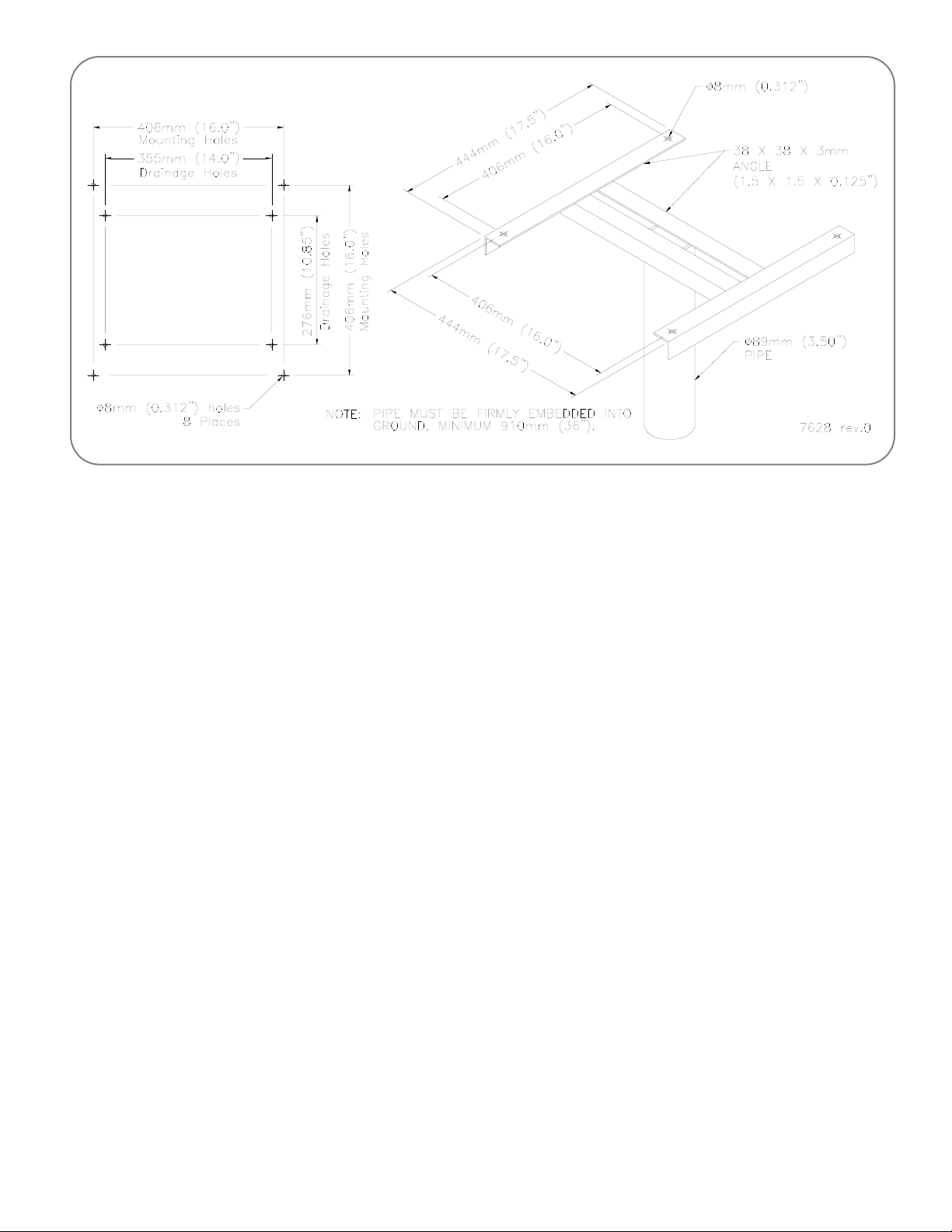
2.1.5 The TEG must be mounted to a firm and stable base. The base must be level and may not
deviate more than 3º (50 mm per meter) (0.5 in. per foot). The TEG should be mounted at a
height sufficient to prevent direct flooding or heavy snowfall from interfering with the flow of
cooling or intake air. It is convenient for the operator if the mounting base is about 900 mm
(36 in.) off the ground.
If the TEG is installed near a building or other large object that may obstruct the flow of wind,
experience indicates that a good location is on the windward side, a minimum of 15 meters
Global Thermoelectric 2-2
23658 Rev. 4
Figure 5 TEG Mounting
(45 feet) from the object or on the roof if possible. Be sure that the TEG's location relative to
buildings and fuel tanks are in accordance with local regulations.
WARNING: Operation of TEG on an unstable or non-level base or in locations where
cooling air flow may be obstructed will cause overheating of the TEG.
2.1.6 A field proven mounting base arrangement is shown in Figure 5.
2.1.7 To install the Shutdown Relay Assembly, thread the male end of the relay assembly into the
bottom of the Shut-Off Valve (found on the fuel system). Using a 3/8 in. wrench, tighten the
joint. DO NOT OVER TIGHTEN. Position the relay with the female end of the assembly
pointed towards the back of the cabinet. Carefully fit the male end of the thermocouple into
the female end on the relay assembly and tighten the threads with the 3/8 in. wrench, again
be careful not to over tighten. Bends in the thermocouple should have a large radius and care
must be taken NOT to break the thermocouple at the burner joint.
2.2 Data Plate Information
2.2.1 The data plate is located on the inside of the cabinet door. The data plate indicates the following information:
a) Fuel type: An "X" is stamped in the appropriate box for Natural Gas or Propane. Each
of these fuels uses several different fuel system components, therefore, the TEG
should only be used with the fuel indicated.
Global Thermoelectric 2-3
23658 Rev. 4
b) Model Number: The model number on the data plate is interpreted as follows:
8550(*) - (**) (***)
* Fuel Type: L = Propane
N = Natural Gas
** Power Conditioner Nominal Output Voltage: 12, 24 or 48V
*** Factory Options:
SI = Spark Ignition
SO = Automatic Shut-off
c) Fuel Pressure, Power, Voltage: The data plate indicates the fuel pressure, power and
voltage that were measured during the factory performance test. The operating fuel
pressure, voltage and Set Power must be determined and adjusted as per section 2.4
and 2.5.
d) Serial Number: The serial number is a unique number assigned by Global
Thermoelectric to provide traceability.
Please indicate both the complete Model number and Serial number when contacting Global
Thermoelectric.
2.3 Fuel Supply
2.3.1 The fuel pressure regulator maximum inlet
pressure is 1720 kPa (250 psi). Make sure
that the supply pressure will never exceed this
value. For good stability fuel should be supplied to the regulator at above 207 kPa (30
psi). If it is expected that the supply fuel pressure will vary greatly, the use of an additional
primary regulator is suggested so that the input
pressure to the internal fuel pressure regulator
is relatively constant.
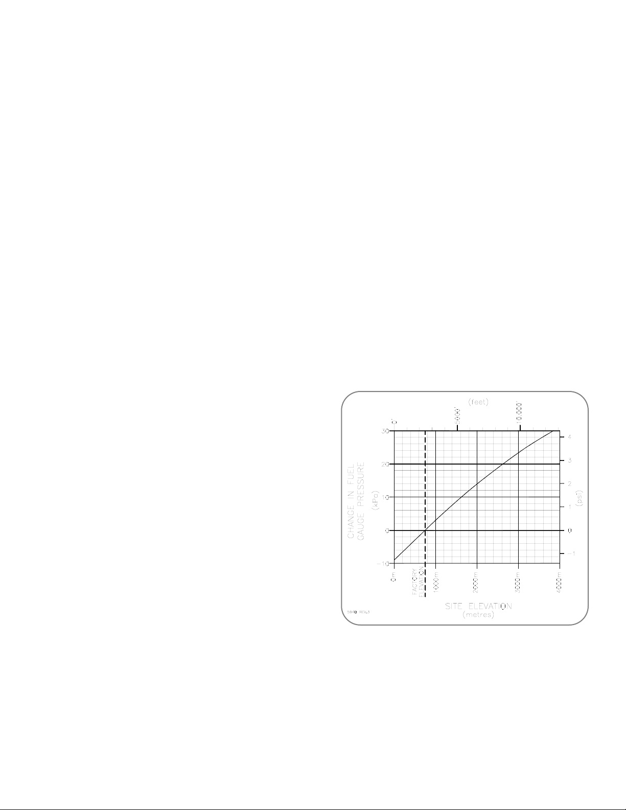
2.3.2 Check that the fuel pressure is still close to
where it was set at the factory. This pressure
is marked on the inside of the door of the cabinet. The fuel pressure supplied may need to
be adjusted for altitude. Figure 6 shows the
correction for variation from the factory altitude
of 750m (2460 ft).
2.3.3 If propane is used at temperatures below -20ºC (-4ºF) the vapour pressure may not be sufficient, see section 1.6.2. If propane is used at temperatures below 5ºC (41ºF) freezing of
moisture in the propane may occur. It is recommended that pure Methyl Hydrate be added in
the ratio of 1 to 800 by volume as an antifreeze additive.
Figure 6 Altitude Adjustment
Global Thermoelectric 2-4
23658 Rev. 4
2.3.4 A fuel shut-off valve must be installed between the TEG and the fuel supply. All fuel piping
should be done in accordance with local regulations. Inspect fuel lines and fittings to ensure
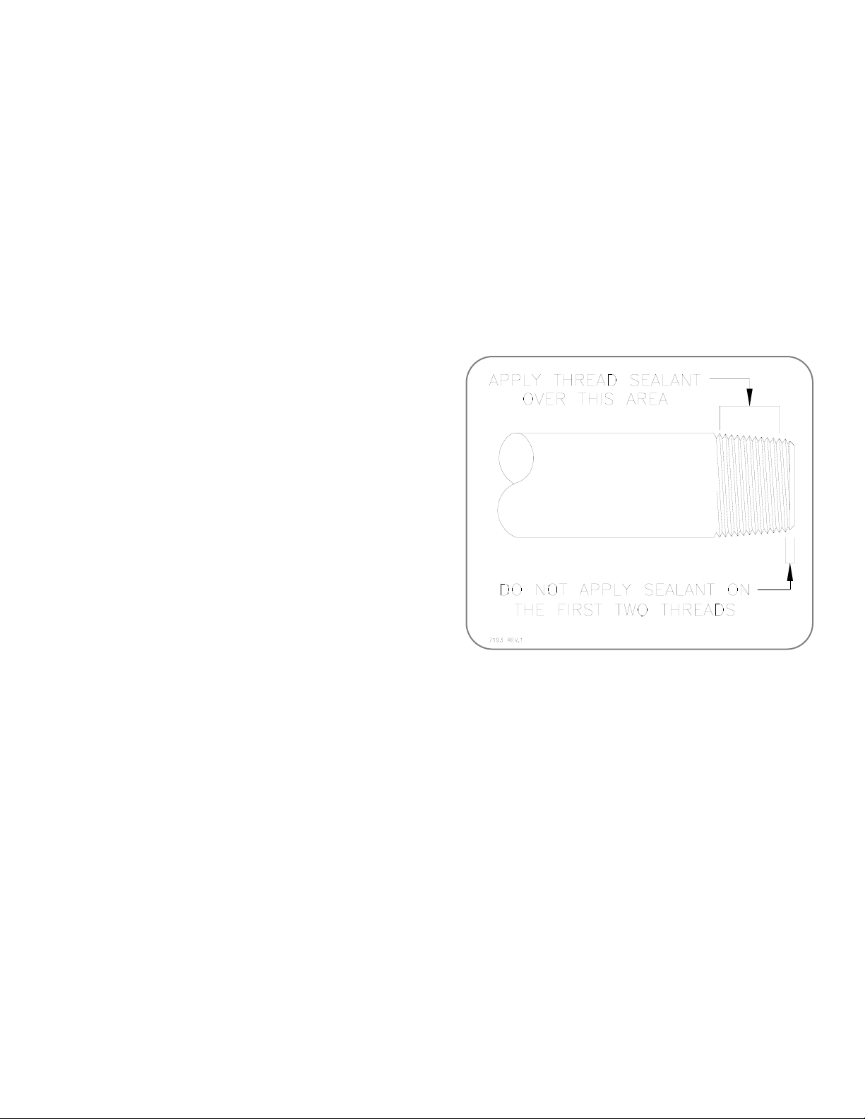
that they are free of foreign material. Apply teflon tape sealant as illustrated in Figure 7 to
minimize fuel line contamination. Purge fuel lines of all air.
2.3.5 If it is expected that the fuel may contain moisture or other contamination, a filtering or fuel
conditioning system must be used. Consult Global Thermoelectric for more information.
2.3.6 The TEG is equipped with a 1/4 in. NPT male connector. Remove the plastic protective cap
and connect the fuel line. Leak check the complete fuel system.
WARNING: Use only the type of fuel indicated on the data plate, see section 2.2. The
maximum inlet fuel pressure must never exceed 1720 kPa (250 psi).
2.4 Ignition and Start Procedure
2.4.1 Before attempting start the Model 8550 TEG,
the operator should ensure that the fuel system has been properly installed as per section
2.3. The operator should also understand the
Electrical Output Characteristics in Figure 3,
definition of terms in section 1.2, and the
operation of the Power Conditioner supplied
for this TEG.
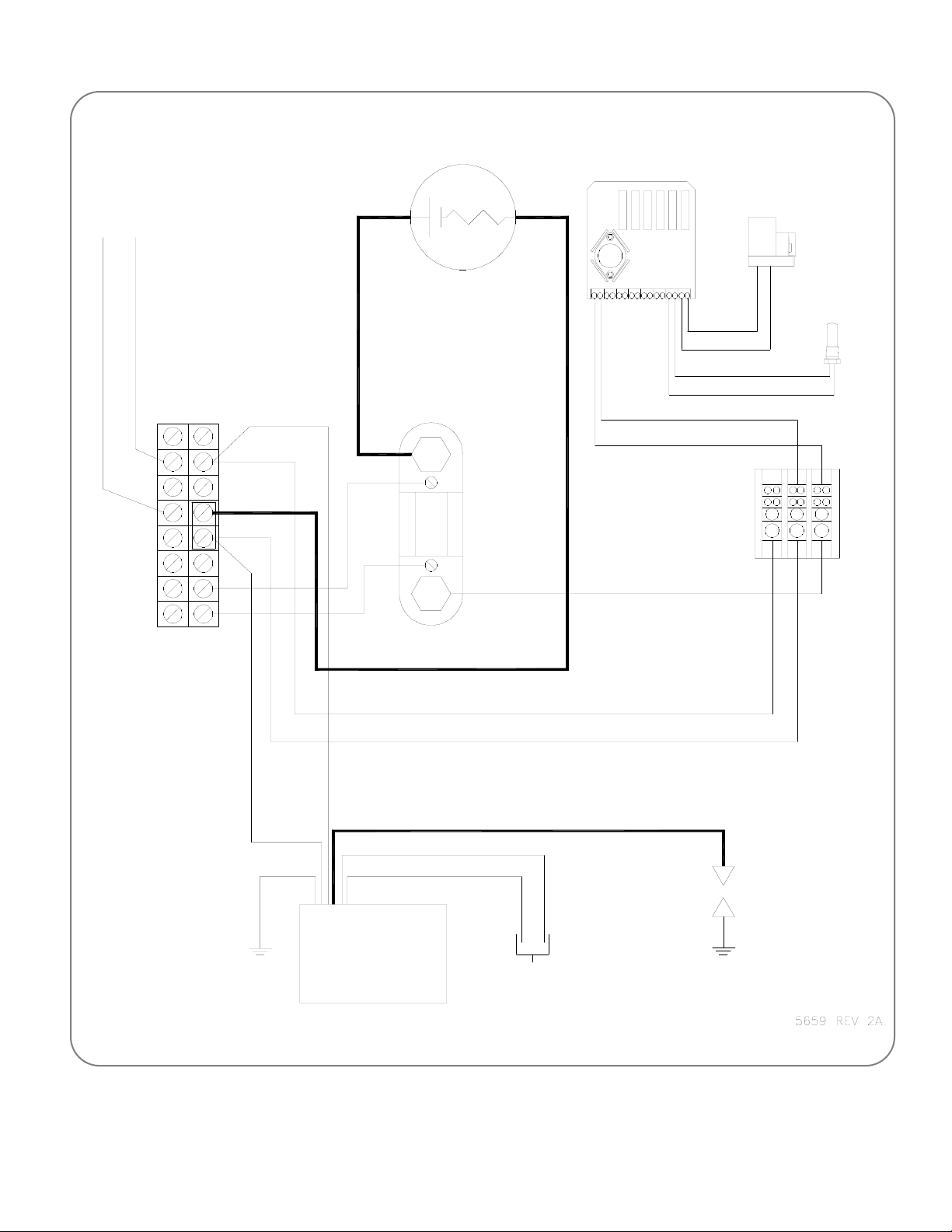
2.4.2 Before starting the TEG familiarize oneself
with the basic wiring diagram Figure 8.
Identify the various components and find their
location on the TEG system. Also familiarize
oneself with the operations of the power conditioner and how to adjust the voltage.
2.4.3 The customer load must be disconnected for start up and power adjustment. It is best to
remove both the positive and negative load wires at terminals 2 and 4 of Terminal Block TB-
1.
WARNING: Before starting, make sure that the Power Unit output wires are connect-
ed to Power Conditioner input.
2.4.4 Starting, heat up and power adjustment are made easier by the use of the Start-Up Data
Sheets in the back of this section. It is suggested that these sheets be used during start-up.
First determine the required Set Power for the current ambient air temperature and wind
speed. Enter these in the Start-Up Data Sheet. See Table 3 for the corrected air temperature and enter it in the Start-Up Data Sheet. Use this corrected air temperature with Figure 4
to find the required Set Power and enter it in the Start-Up Data Sheet. This is the power to
which the TEG must be set at your ambient conditions so that rated power will be generated
when the ambient conditions return to standard.
Figure 7 Applying Thread Sealant
Global Thermoelectric 2-5
23658 Rev. 4
+-
WHT/RED
WHT/RED
RED
BLK
POWER UNIT
50A/50mV
SHUNT
TB-1
WHT/RED
WHT/BLK
WHT/BLK
+-
+-
GRN
GRD
WHT/BLK
WHT/RED
BRN
ORN
SI HIGH VOLTAGE CABLE
ELECTRODE
TO
CUSTOMER
LOAD
TO POW ER
CONDITIONER
FROM POWER
CONDITIONER
SI
MODULE
BOX
-+ -+
+
-
6720 LIMITE R
TERMINAL
BLOCK
SHUTDOWN
MODULE
SHUTDOWN
RELAY
SHUTDOWN
THERMOSTATS
+-
BLK
RED
WHT
WHT
BLK/WHT #20
RED/WHT #20
QTY 6
SPARK
TO PRESSURE
SWITCH
12344567
Figure 8 Wiring Diagram, 8550 TEG

Global Thermoelectric 2-6
23658 Rev. 4
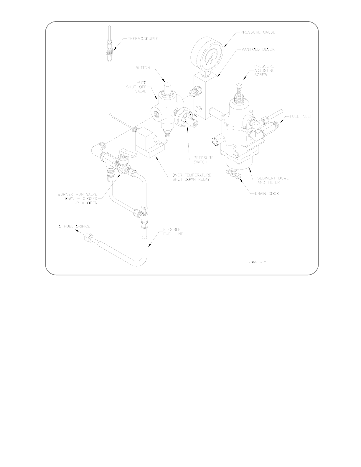
2.4.5 Starting procedure for TEG with Spark Ignition (SI) and Automatic Shut-Off (SO) options, see
Figure 9. Turn on the fuel supply to the TEG and observe the fuel pressure at the pressure
gauge. The pressure should be in the range of 110 to 150 kPa (16 to 22 psi) for propane or
34 to 69 kPa (5 to 10 psi) for Natural Gas. If the pressure is lower, increase it by turning the
screw on the pressure regulator clockwise. If the pressure is higher, decrease it by turning
the screw on the pressure regulator counterclockwise and venting the pressure through the
burner by momentarily pressing the button on the Auto Shut-Off Valve.
Check the operation of the ignition system by shorting the terminals of the Pressure Switch.
The spark ignitor clicking sound should be heard, if not, trouble shoot the system as indicated in section 3.6. The clicking sound should be rapid and strong.
Install a voltmeter to read the Power Unit voltage measured at terminals 6(+) and 4(-) of
TB-1.
Close the air plate on the venturi completely (see Figure 11). Shut off the fuel supply at the
external valve.
Check that the Burner Run Valve is closed (down). Open the Auto Shut-Off Valve by pressing the button with one hand to keep the button depressed. Open the external valve, the clicking sound of the spark ignitor should be heard. Ignition will occur with a series of banging
sounds. Combustion will be indicated by a small rise in the Power Unit voltage and change
in the sound. Continue to hold down the button. If ignition does not occur within 5 seconds,
release the button and check to make sure that fuel is reaching the burner, i.e. that the fuel
lines are purged of air. If fuel is reaching the burner, trouble shoot the ignition system, see
section 3.6.
As soon as combustion is noted slowly open the Burner Run Valve. Open the air plate to its
full Open position. Achange in the burner sound will be noted. Continued combustion will be
indicated by a continued rapid rise in the power unit voltage. Continue to hold down the button. If a flame outage is noted close the Burner Run Valve to re-establish the flame and then
reopen the valve.
WARNING: Do not allow the burner to operate with only the Auto Shut-Off valve open
for more than 5 minutes. The Burner Run Valve should be opened as soon
as the flame is burning.
Global Thermoelectric 2-7
23658 Rev. 4
Figure 9 Fuel System Components, SI and SO
Five minutes after opening the Burner Run valve fully press the button and slowly release the
button. The internal electromagnet should now hold the Auto Shut-Off valve open. If the valve
does not stay open, immediately press the button again and hold for one more minute, then
try to release it again. If the valve again does not stay open, trouble shoot the Automatic ShutOff system, see section 3.7.
Once the burner is started proceed to section 2.5, Heat Up and Power Adjustment.
If the operation of the burner must be stopped, turn off the fuel supply at the external valve.
Then close the Burner Run Valve, the Auto Shut-Off valve will close when the burner cools
down and its internal electromagnet no longer holds the valve open.
WARNING: Once the burner is started, you must proceed to the Heat Up and Power
Adjustment (section 2.5). Failure to do so may overheat the power unit.
Global Thermoelectric 2-8
23658 Rev. 4
Figure 10 Power Calculation
2.5 Heat Up and Power Adjustment
2.5.1 Once the burner is operating the Power Unit output voltage should climb rapidly to about 25
Volts. If the voltage levels off below 25 Volts or climbs above 25 Volts adjust the power conditioner as per its manual.
WARNING: Do Not allow the power unit voltage to exceed 35 Volts. If the power con-
ditioner fails to control the voltage, turn off the burner.
2.5.2 Once the voltage is about 25 Volts observe the Power Unit current by measuring the voltage
across the Current Shunt at terminals 6(+) and 7(-) of TB-1. The shunt is rated 50 Amp/50
mV; 1 mV across the shunt equals 1 Amp. The current will initially rise rapidly and then slow
down as the current reaches its operation point. Continue to monitor the Power Unit voltage
at terminals 6(+) and 7(-) of TB-1. This voltage should remain at 25.0 Volts. Adjust the Power
Conditioner if needed.
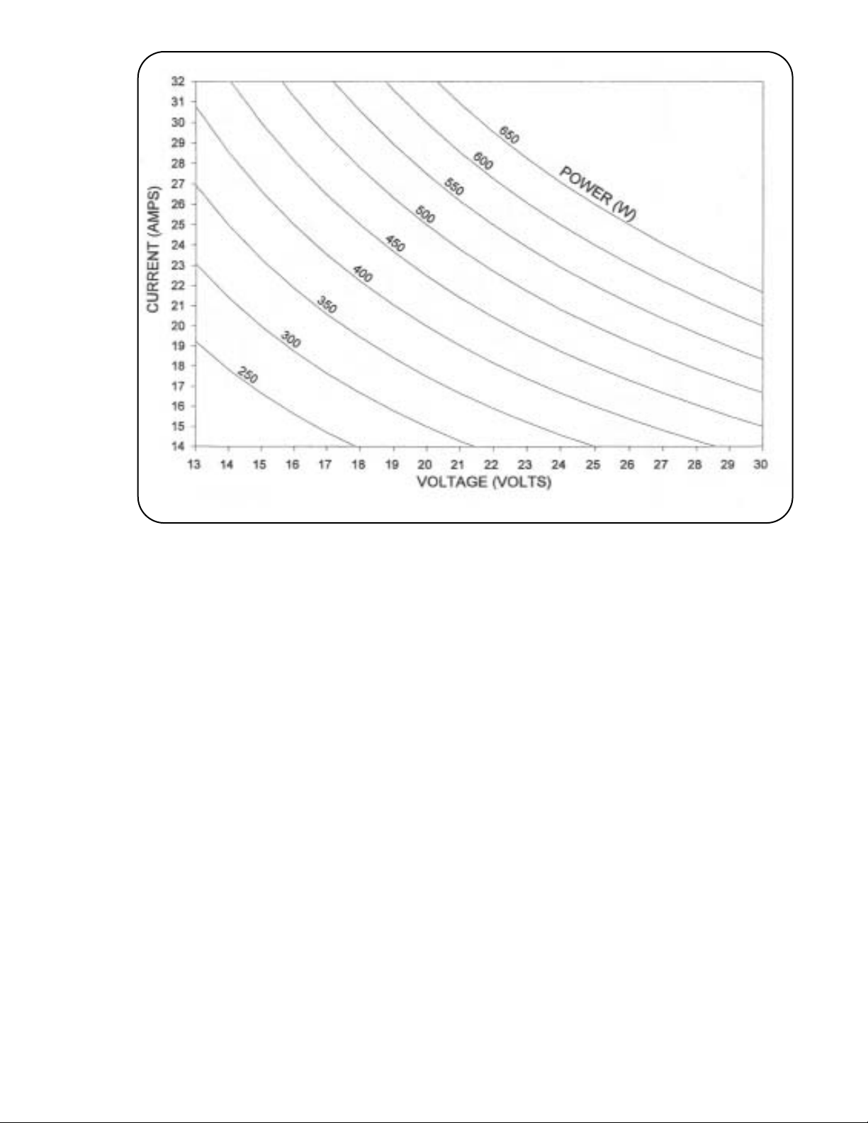
2.5.3 Output Power is the product of the Power Unit voltage multiplied by the Power Unit current,
ie. 25.0 Volts and 22.2mV (Amps) gives 25.0 x 22.2 = 555.0 Watts. Figure 10 may be used to
perform the multiplication. Find the voltage on the bottom axis and draw a line vertically up.
Find the current (or mV measured across the shunt) on the side axis and draw a line horizontally across. The power is indicated by the power line nearest the intersection of the two lines,
interpolate if necessary.

Global Thermoelectric 2-9
23658 Rev. 4
2.5.4 Refer back to the Start-Up Data Sheet as noted in section 2.4.4. The Power Unit output
power must be adjusted to the Set Power as determined in section 2.4.4. As much as possible, keep the cabinet door closed during the warm up period. It takes about one full hour for
the power to stabilize. Monitor and record the power at the 15, 30, 40, 50 and 60 minute intervals on the Start-Up Data Sheet.
2.5.5 As the heat pipes start to operate they may make some crackling sounds. This is normal.
About 15 minutes after ignition check the tip of each heat pipe to see if they are getting warm.
If one or more heat pipe is not getting warm, recheck them after an additional 10 minutes. If
one or more heat pipe continues to remain cold up to 2 in. (50 mm) from the tip, trouble shoot
the cooling system as per section 3.5. Note, during cold or windy conditions, it may be hard
to notice any warming of the heat pipes. If all the fins are about the same temperature, then
the heat pipe is working well.
2.5.6 As the Power Unit output power climbs, ensure that the Set Power level is not exceeded. The
power level should be at about 70 to 80% of Set Power within 30 minutes after ignition. If the
power is above 80% after 30 minutes, continue to monitor the Power Unit output power and
be prepared to reduce the fuel pressure if the power rises above the Set Power level. If the
power level rises more than 10 watts above Set Power, initially reduce the pressure by 1 psi
and wait 3 minutes, then determine if further adjustment needed. Remember that it will take
up to 10 minutes for the full effect of the fuel pressure change to stabilize. Record any
changes in fuel pressure on the St art-Up Dat a Sheet. If the power level is less than 70% af ter
30 minutes, the fuel pressure is too low but, do not adjust it until the power level has stabilized.
2.5.7 Compare the Power Unit output power at 60 minutes with that at 50 minutes. The two readings should be within 5 Watts of each other. If the power level is not yet stabilized, wait another 10 minutes. Once the power level has stabilized determine if the Power Unit output power
is within about 5 Watts of the Set Power.
If the power is within 5 Watts of Set Power, proceed section 2.5.8, Air Shutter adjustment.
If the power is more than 5 Watts above Set Power, decrease the fuel pressure by approx-
imately 1.7 kPa (0.25 psi), no more than 3.4 kPa (0.50 psi), and wait 10 minutes. After 10
minutes determine if further adjustment is needed. Once the Power Unit output power has
stabilized to within 5 Watts of Set Power and stayed there for at least 15 minutes, proceed to
section 2.5.8, Air Shutter adjustment.
If the power is more than 5 Watts below Set Power, increase the fuel pressure by approximately 1.7kPa (0.25 psi), no more than 3.4 kPa (0.50 psi), and wait 10 minutes. If the power
is more than 20 Watts below Set Power, increase the fuel pressure approximately 3.4 kPa
(0.50 psi), no more than 6.8 kPa (1.00 psi). After 10 minutes determine if further adjustment
is needed. Once the Power Unit output power has stabilized to within 5 Watts of Set Power,
and stayed there for at least 15 minutes, proceed to section 2.5.8, Air Shutter adjustment.
Global Thermoelectric 2-10
23658 Rev. 4
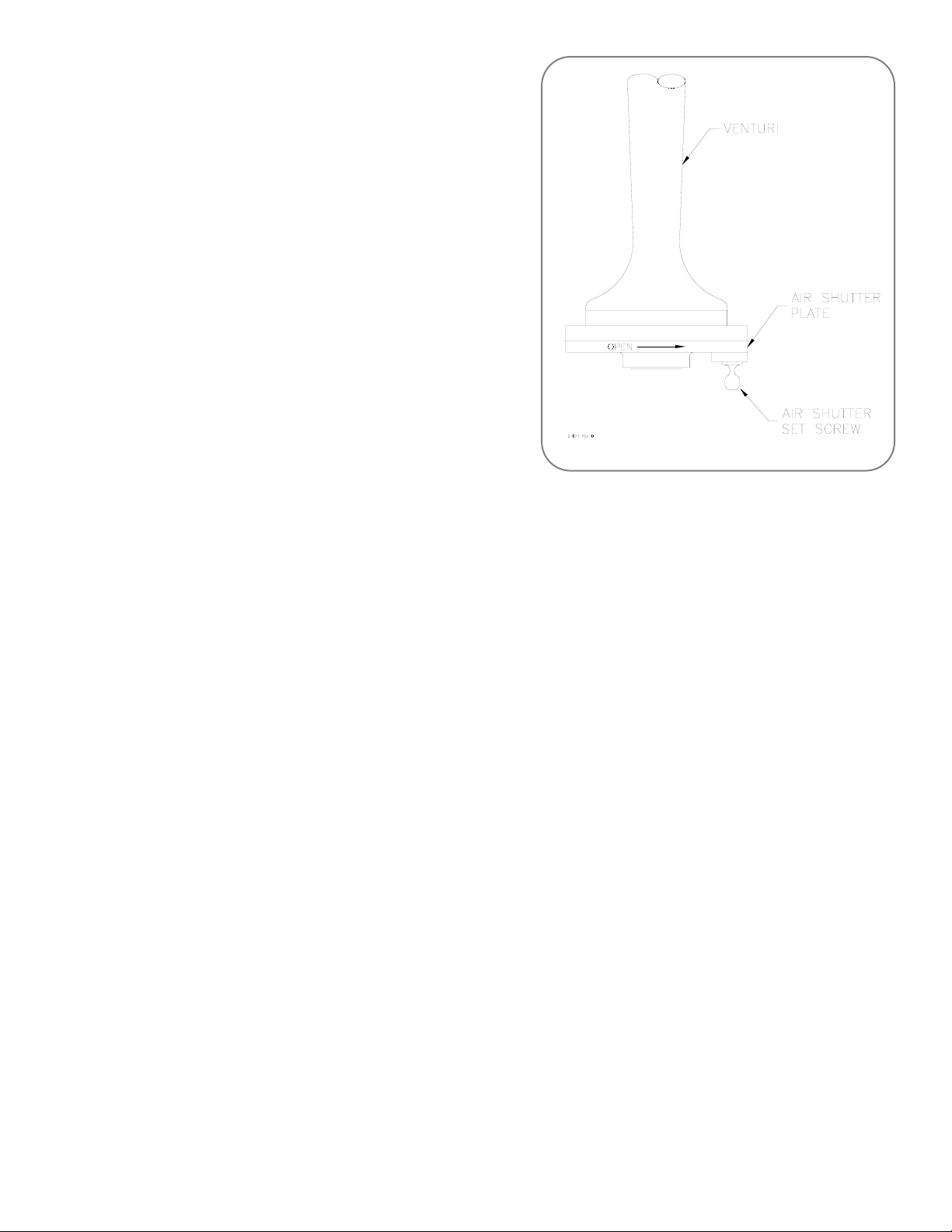
2.5.8 Once the air shutter is set to full open, the unit
should run properly, and no further adjustments
should be necessary. However, perform the following test to determine if the air shutter is correctly adjusted for the site conditions. Identify the
air shutter parts in Figure 11. The position of the
cabinet door will affect the air shutter adjustment
reading. For this reason, open the door only to
adjust the air shutter and keep the door closed as
much as possible. Take an initial power reading
after the cabinet has been shut for at least 15
minutes and record this reading on the Start-Up
Data Sheet. Now close the air shutter by 3 mm
(1/8 in.) and close the cabinet door. After 10 minutes take a power reading.
If this reading is higher than the initial reading,
close the Air Shutter another 3 mm (1/8 in.) and
wait 10 minutes. Repeat this until the power no
longer rises. The air shutter must then be
opened another 6 mm (1/4 in.) to allow for
changes in the ambient site conditions. Again wait 10 minutes and check that the Power Unit
output voltage is within 5 Watts of Set Power, adjust the fuel pressure as per section 2.5.7 if
needed. Further Air Shutter adjustment will not be required.
If this reading is lower than the initial reading, open the Air Shutter 3 mm (1/8 in.) past the initial setting, close the cabinet door and wait 10 minutes. If after 10 minutes the power reading is the same or lower than the initial reading, the Air Shutter is now correctly adjusted. If
after 10 minutes the power is higher than the initial reading, open the Air Shutter another 3
mm (1/8 in.) and wait 10 minutes. Repeat this until the power no longer rises. The Air Shutter
must then be opened another 5 mm (3/16 in.) to allow for changes in the ambient site conditions. The Air Shutter may reach its maximum open position before the power reaches its
maximum, in this case, leave the Air Shutter at its maximum setting. Wait 10 minutes and
check that the Power Unit output power is within 5 Watts of Set Power, adjust the fuel pressure as per section 2.5.7 if needed. Further Air Shutter adjustment will not be required.
If this reading is the same as the initial reading, open the Air Shutter 6 mm (1/4 in.) and close
the cabinet door. After 10 minutes check that the Power Unit output power is within 5 Watts
of Set Power. Adjust the fuel pressure as per section 2.5.7 if needed. Further Air Shutter
adjustment will not be required.
2.5.9 If the TEG is factory new or has just undergone a major overhaul, the Power Unit output power
may drift slightly over the first few weeks of operation. It may be necessary to adjust the fuel
pressure slightly to obtain Set Power after this time.
Figure 11Air Shutter Adjustment

Global Thermoelectric 2-11
23658 Rev. 4
2.6 Applying Customer Load
2.6.1 The TEG should now be operating at the correct power level. Before applying the customer
load, ensure that all wire connections are tight.
2.6.2 Adjust the Power Conditioner output to the desired customer voltage as per the Power
Conditioner manual.
2.6.3 Connect the customer load to the Power Conditioner at terminals 2(+) and 4(-) of terminal
block TB-1. Be sure that the Power Unit remains connected to the Power Conditioner.
2.6.4 Turn the circuit breaker on the Power Conditioner to the ON position. Close and latch the
cabinet.
WARNING: The Power Unit output must always remain connected with the Power
Conditioner.
2.7 System Performance Log
2.7.1 A System Performance Log is located at the back of section 3. It is recommended that this
log be used to monitor system performance each time the site is visited. This information is
valuable for future reference. If this site is a multiple TEG installation, it may be desirable to
keep the log in a common maintenance book for the site.

Global Thermoelectric 2-12
23658 Rev. 4
 Loading...