

Global Telecom SWLR41 Users manual
AM4000D Outdoor CPE
User Manual
Page 1

Tableofcontents
1. OVERVIEW ................................................................................................................................................ 4
1.1. USER INTERFACE SPECIFICATION ......................................................................................................... 4
1.2. LTE INTERFACE SPECIFICATION ............................................................................................................ 4
2. GETTINGSTARTED ................................................................................................................................. 5
2.1. PACKING LIST AND CPE UNIT ................................................................................................................ 5
2.2. INSTALLING THE EQUIPMENT ................................................................................................................. 5
Device logic connection ...................................................................................................................... 5
Installing Outdoor Unit (ODU) ............................................................................................................ 6
LED Display ......................................................................................................................................... 7
3. MANAGING CPE DEVICE ...................................................................................................................... 7
3.1. WEB LOGIN--192.168.0.1 ................................................................................................................... 7
3.2. LTE STATUS DISPLAY-OVERVIEW ......................................................................................................... 8
3.3. LTE CONFIGURATION .......................................................................................................................... 10
Radio Settings-ND&S Configure ..................................................................................................... 10
APN Setting-Bearer configure ......................................................................................................... 10
3.4. ENODEB SELECTION ........................................................................................................................... 12
PLMN Selection ................................................................................................................................. 12
eNodeB Setting ................................................................................................................................. 13
3.5. NETWORK CONFIGURATION ................................................................................................................. 13
Modify MTU Size ............................................................................................................................... 13
Change model from Router to Bridge ............................................................................................ 14
3.6. SERVICE CONFIGURATION-DMZ SETTING .......................................................................................... 15
3.7. SYSTEM MAINTENANCE ....................................................................................................................... 15
Telnet Enable (for beta release) ...................................................................................................... 15
TR069 Configuration ......................................................................................................................... 16
Firmware Upgrade over HTTP ........................................................................................................ 17
Change Password ............................................................................................................................. 18
Load Factory Default ........................................................................................................................ 18
4. FAQ AND TROUBLESHOOTING ........................................................................................................ 18
Page 2
PLEASE READ THESE SAFETY PRECAUTIONS!
RF Energy Health Hazard
The radio equipment described in this guide uses radio frequency transmitters. Although
the power level is low, the concentrated energy from a directional antenna may pose a
health hazard.
Do not allow people to come in close proximity to the front of the antenna while the transmitter is
operating.
Protection from Lightning
Before connecting this instrument to the power line, make sure that the voltage of the
power source matches the requirements of the instrument. The unit must be standards.
Disposal and Recycling Information
Pursuant to the WEEE EU Directive electronic and electrical waste must not be disposed of
with unsorted waste.Please contact your local recycling authority for disposal of this product.
Reduction of Hazardous Substances
This CPE is compliant with the EU Registration, Evaluation, Authorisation and Restriction
ofChemicals (REACH) Regulation (Regulation No 1907/2006/EC of the European
Parliament
and of the Council) and the EU Restriction of Hazardous Substances (RoHS) Directive(Directive
2002/95/EC of the European Parliament and of the Council).
FCC Notice, USA
This device complies with Part 15 of the FCC Rules. Operation is subject to the following two
conditions:
(1) This device may not cause harmful interference, and (2) this device must accept any interference
received, including interference that may cause undesired operation.
NOTE 1: This equipment has been tested and found to comply with the limits for a Class B digital
device, pursuant to part 15 of the FCC Rules. These limits are designed to provide reasonable
protection against harmful interference in a residential installation. This equipment generates, uses
and can radiate radio frequency energy and, if not installed and used in accordance with the
instructions, may cause harmful interference to radio communications. However, there is no
guarantee that interference will not occur in a particular installation. If this equipment does cause
harmful interference to radio or television reception, which can be determined by turning the
equipment off and on, the user is encouraged to try to correct the interference by one or more of the
following measures:
- Reorient or relocate the receiving antenna.
- Increase the separation between the equipment and receiver.
-Connect the equipment into an outlet on a circuit different from that to which the receiver is
connected.
-Consult the dealer or an experienced radio/TV technician for help.
NOTE 2: Any changes or modifications to this unit not expressly approved by the party responsible for
compliance could void the user's authority to operate the equipment.
Page 3
FCC Radiation Exposure Statement:
This equipment complies with FCC radiation exposure limits set forth for an uncontrolled environment.
This equipment should be installed and operated with minimum distance 30cm between the radiator &
your body.
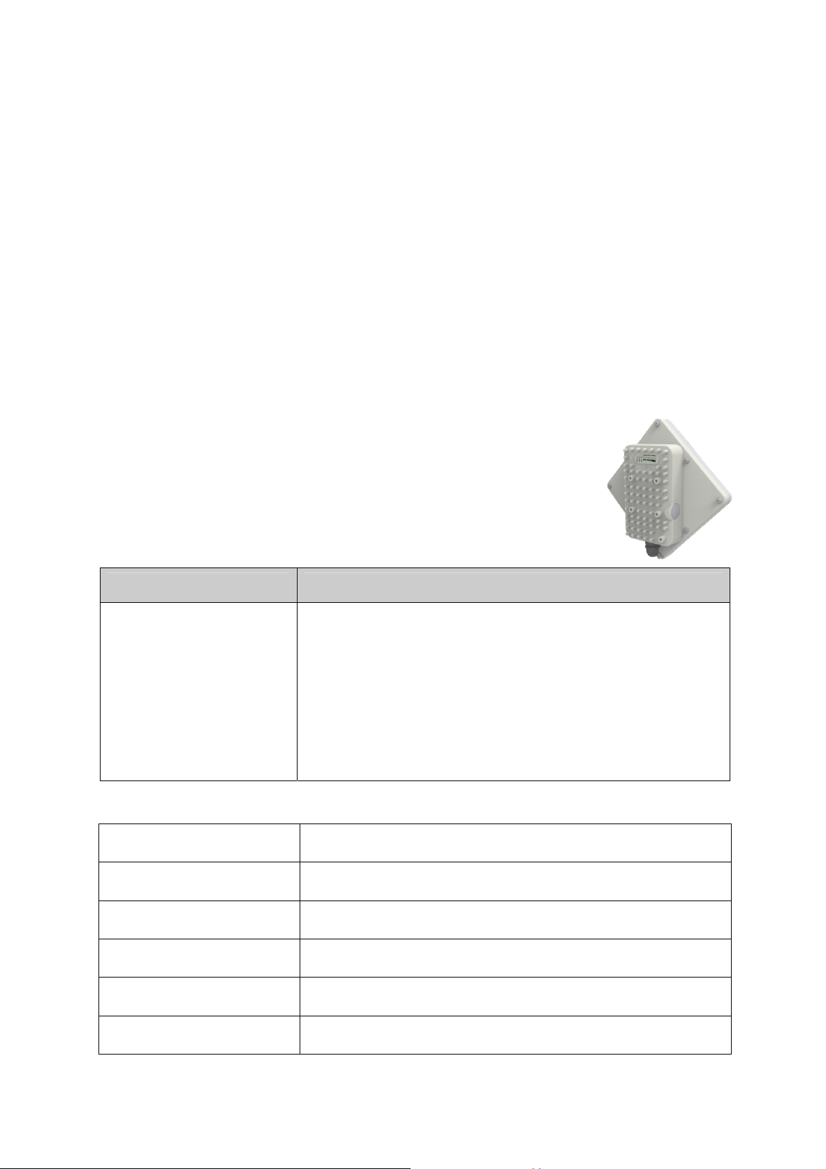
1. Overview
The ODU is a high performance 4G LTE outdoor CPE product designed
to enable quick LTE fixed data service deployment to the remote
customers. It provides high data throughput and networking features to
end users who need both bandwidth and quality service in the remote
area.
1.1. User Interface Specification
Model Description & User Interface
- Panel antenna: B41 13dBi
- 1 RJ45 10/100M LAN Port
ODU
- PWR, RUN, LAN, SIM, LTE(1-5) LEDs
- 24 VDC PoE supply, ODU Power <12 Watts
- Dimensions: 203 mm (L) × 203 mm (W) × 76.5 mm (D)
- Weight: < 1.5 Kg
1.2. LTE Interface Specification
Frequency Bands Band 41
Radio Access 3GPP LTE Release9
Operation Mode TDD, 2RX, 1TXD, DLMIMO
Output Power > 23 dBm at antenna port
Throughput Category 4
SIM Support SIM card slot
Page 4
2. GettingStarted
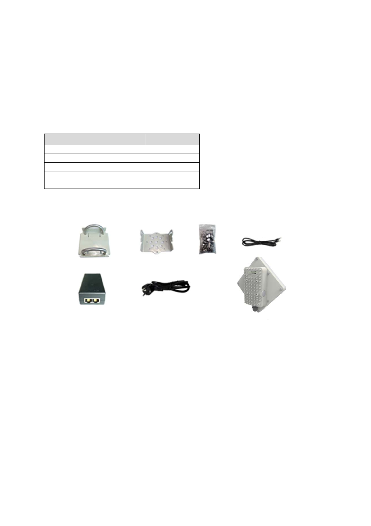
2.1. Packing list and CPE Unit
Upon receiving the product, please unpack the product package carefully. Each product is shipped
with the following items:
Table 2-1 Packing List
Outdoor CPE Products Quantity
ODU unit 1
Power adapter 1
Power Line 1
Mounting brackets 1
PC Ethernet Cable 1
If you find any of the items missed, please contact our local distributor immediately.
CPE Unit:
Please unpack the package and check the units as following list.
2.2. Installing the Equipment
Device logic connection
For outdoor CPE product, it is suggested that the CPE device be installed in a shaded area to
avoid direct sun light exposure which may cause over heat in certain extreme weather condition.
The CPE should be properly grounded for proper protection against lighting or power surge.
To power on the device, the outdoor CPE must uses a 24V PoE integrated DC power supply
adapter. The power adapters can operate in 90-250V AC range and therefore can be used in
different country. Once the device is powered up, the user should wait for about 2 minutes before
the device becomes operational. For CPE with the RUN LED indicator, a slowly flashing light
indicates the system has completed the startup procedure.
To connect PC, LAN switch or other type of IP device to the CPE product, the user should use
standard CAT5 Ethernet cable and connect to the appropriate LAN port. Once connect the CPE
LAN LED indicator should come on.
Page 5
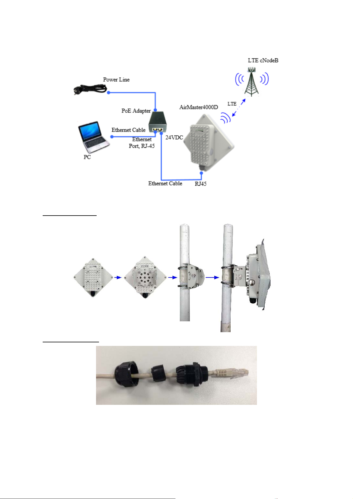
Installing Outdoor Unit (ODU)
Mounting Bracket::
Header Connection:
Page 6
 Loading...