

Page 1
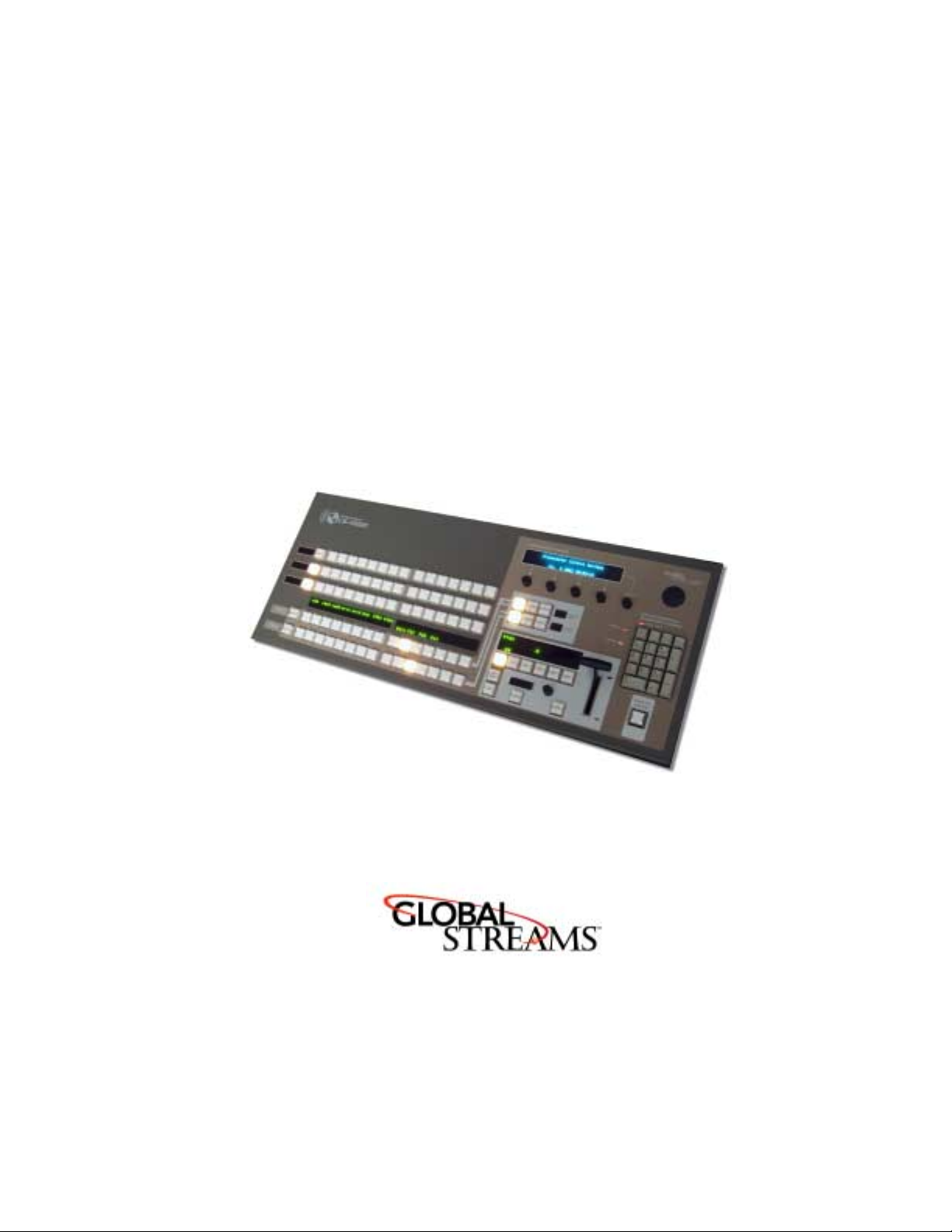
CS-1000
User’s Guide
YYY)NQDCN5VTGCOUEQO
Page 2

Copyrights. Copyright 1998-2003, GlobalStreams, Inc. All rights reserved. The GlobeCaster System
software, content and documentation are copyright 1998-2003. This User Manual may not, in whole or
in any part, be copied, photocopied, reproduced, translated, or reduced to any electronic medium or
machine readable format without the prior written consent of an authorized representative from
GlobalStreams, Inc.
Trademarks
GlobeCaster logos are trademarks of GlobalStreams, Inc. Windows and Windows NT are registered
trademarks of Microsoft Corporation.
Patents
without limitation patent numbers 5,941,997, 5,978,876, 5,872,565. Other patents, in the United States
and othercountries, are pending.
. GlobalStreams, GlobalStreams and the GlobalStreams logos, GlobeCaster and the
. Various technology in the GlobeCaster System is patented in the United States, including
Page 3

table of contents
control surface
user’s guide
i
Ch1: introduction
features
technical specifications
contact information
Ch2: connectivity
Ch3: functions
video buses
freeze/strobe controls
comm/power status lights
number pad
fade to black
effect controls
t -bar
soft labels
configuration panel
Ch4: software changes
FCC Notice
index
....................................................................................I
....................................................................1
......................................................................2
.......................................................2
...........................................................2
...................................................................3
.......................................................................7
..................................................................7
........................................................9
....................................................9
................................................................10
...............................................................11
..............................................................11
.......................................................................18
..................................................................18
.........................................................19
.........................................................27
.........................................................................31
Page 4

ii
table of contents
Page 5
chapter 1
introduction
The CS-1000 is GlobalStream’s Control Surface that is designed to provide
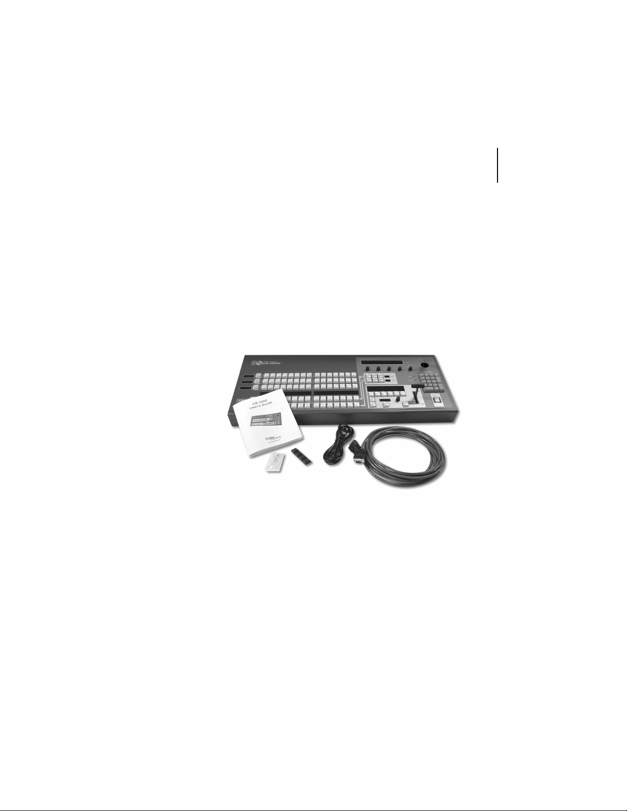
the GlobeCaster user with increased functionality and ease of use in live production applications. Your CS-1000 box contains the following items:
N
M
control surface
user’s guide
1
P
R
CS-1000 Unit
M
Reference Guide
N
RS-422 Cable*
O
*The supplied RS-422 cable was specially manufactured for use with the CS-1000. In the event that this
cable is damaged, contact GlobalStreams for replacement information.
Q
Figur e 1. 1: CS - 10 00 Pack a ge Contents
Power Cable
P
Rubber Feet
Q
Replacement Bulbs
R
O
Page 6

chapter 1
2
introduction
features
• Program/Preview Keyrows—Keyrows that provide dedicated buttons which may be used to route a variety of sources onto the Pro-
gram and Preview busses.
• Freeze/Strobe Control—Physical area that enables you to control
the freeze and strobe rates for the Program and Preview buses.
• Effect Control Section—Dedicated area that allows you to control
the mix of the video busses.
• T-Bar—Provides smooth manual control over wipes, fades, and
effects (as determined by selected mode).
• Fade to Black—A dedicated control to activate/deactivate the Program Out Fade-to-Black function. An illuminated button provides
visual feedback when this feature is being used.
• Control Keypad—Used to trigger numerical shortcuts.
technical specifications
Product Dimensions 31”(w) x 13” (d) x 2.5” (h)*
*Height is measured without T-Bar.
Product Weight 14 lbs.
contact information
If you need further assistance with CS-1000, there are several ways to contact GlobalStreams’ support staff.
Page 7

chapter 2
connectivity
Installing the CS-1000 to your GlobeCaster is a quick and easy process. You
will need to have the following items ready before you can install your CS1000:
• Power Cord (supplied)
• RS-422 Serial Cable (supplied)
• Rubber Feet (supplied)
• GlobeCaster Software 2.8.2 (prefer 2.9 for full functionality)
control surface
user’s guide
3
Page 8
chapter 2
4
connectivity
NOTE:
EQPPGEV[QWT%5
/CMGUWTG[QWTJQUV2%CPF)NQDG%CUVGTWPKVCTGDQVJVWTPGFQHHDGHQTG[QW
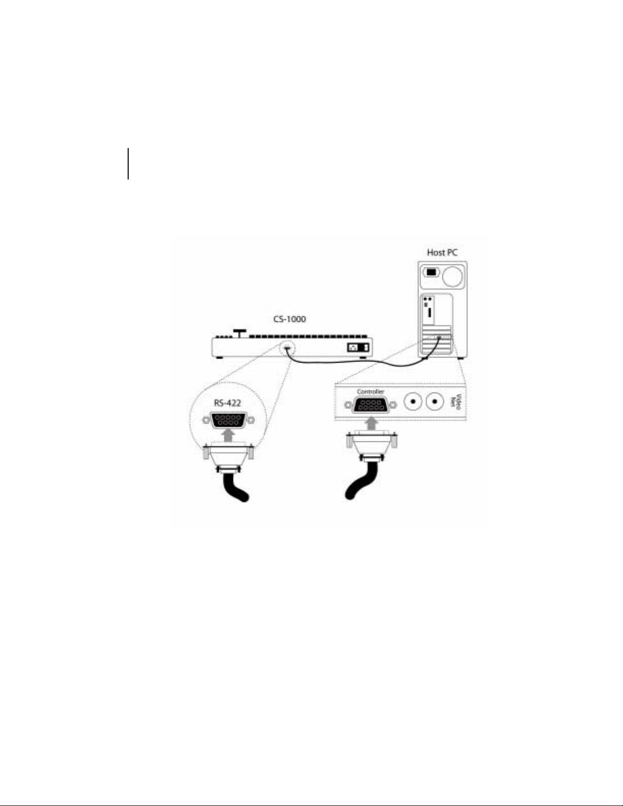
Figure 2.1: Connecting Your CS-1000
Figure 2.1 illustrates how to connect your CS-1000 to your host PC. The CS1000 plugs directly into the VideoNet card on your host PC via the supplied
RS-422 serial cable. To connect your CS-1000 to your GlobeCaster, follow
these steps:
1. Install the rubber feet in the four corners on the bottom of your CS-1000.
2. Place your CS-1000 on a flat surface next to your GlobeCaster and host
PC.
Page 9

control surface
user’s guide
5
3. Remove the RS-422 serial cable from the box and attach one end of the
cable into the port labeled RS-422 on the back of the CS-1000.
4. Locate your VideoNet card on your host PC. The VideoNet card has a
serial port on the back labeled Control Port or Controller. Connect the
other end of the RS-422 cable to this port.
5. Remove the power cable from the box and attach one end to the back of
the CS-1000 and the other end to an outlet.
6. Now it’s time to power all three devices. Be sure to power the devices in
the following order: CS-1000, GlobeCaster unit, and host PC.
Page 10

chapter 2
6
connectivity
Page 11
chapter 3
functions
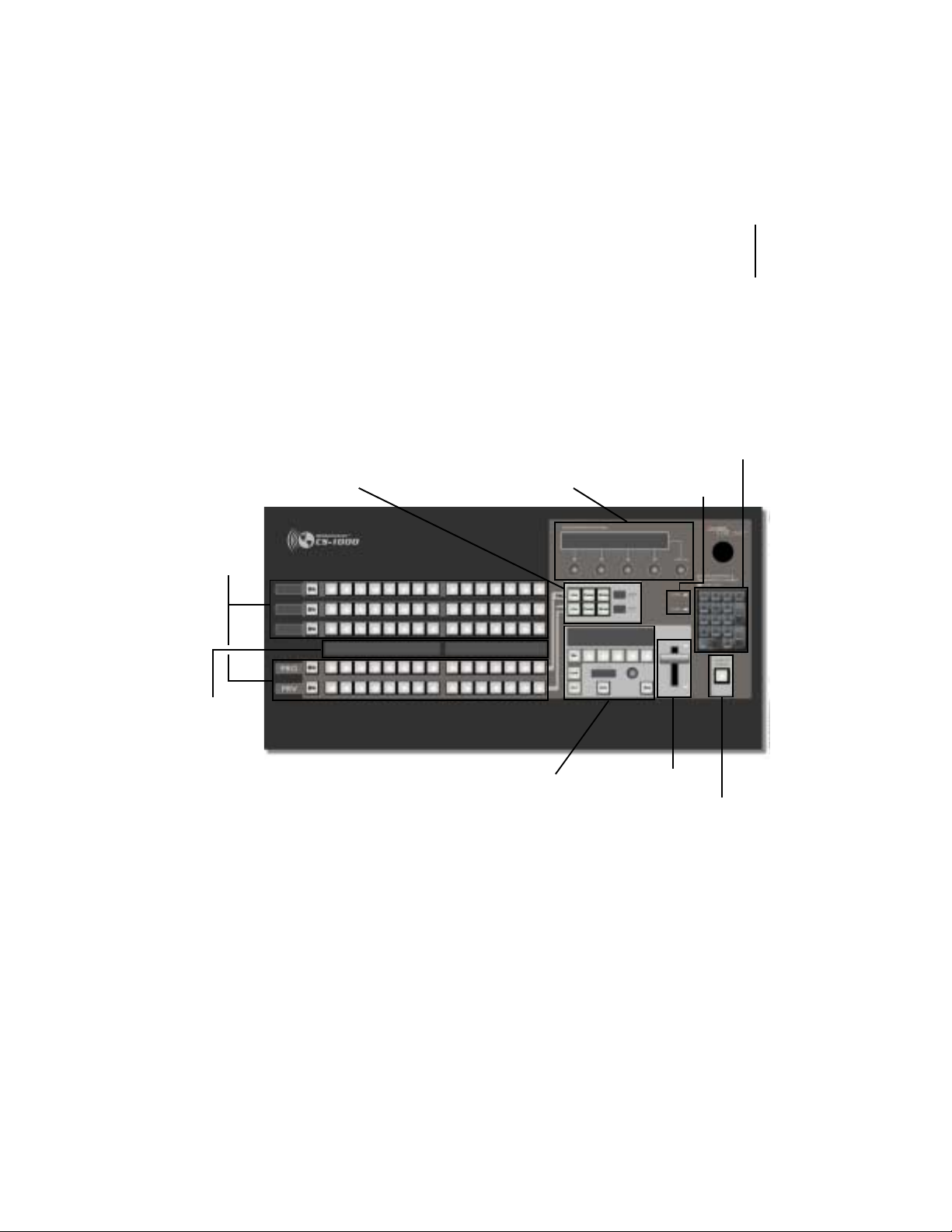
The CS-1000 lets you control every aspect of your broadcast externally and
contains every feature found on a traditional switcher. Let’s take a look at the
buttons and functions on the CS-1000.
video
busses
freeze/strobe
controls
configuration
panel
control surface
user’s guide
number pad
comm/power
status lights
7
soft
labels
effect controls
Figure 3.1: CS-1000 Top View
T-bar
fade to black
video buses
Each row of buttons is called a video bus. Each button represents a channel
of video that is running through your GlobeCaster. The definition of the busses found on the CS-1000 are as follows:
Page 12

chapter 3
8
functions
Aux Bux
Key Preview
Bus
Key Bus
Program Bus
Preview Bus
Another video bus just like the Program bus and the
Preview bus. Certain GlobeCaster configurations with
multiple video paths can use the Aux bus to specify a
third video source for effects using three video sources.
For example, two framestore cards and a warp engine or
two warp engines and a framestore card.
A secondary video bus used to preview what video
source is going to be keyed in over the top of the Program source using the chroma/luma keyer.
Selects what video source is keyed in over the top of
the Program source using the chroma/luma keyer. The
Key bus is only turned on when the chroma/luma keyer
is used.
Represents what is actually going out over the air. This
is the most important bus on the CS-1000, as whatever
is selected here is what is actually broadcast or
recorded. The Program bus must always have a button
selected.
A secondary video bus used to preview video sources to
decide which should go out on the air next. Most transitional video effects take the current Program video
source and replace it with the Preview source. The Preview bus must always have a button selected.
Page 13
control surface
user’s guide
9
freeze/strobe controls
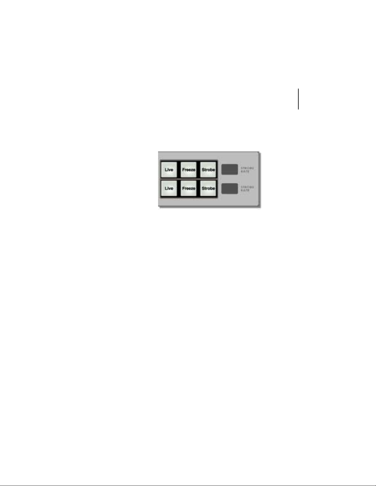
Here are the controls for the freeze and strobe rates for both the Program and
Preview buses.
Figure 3.2 : Freeze/Strobe Controls
Live When lighted, indicates that live video is playing
on the indicated bus.
Freeze Creates a still of the source on the selected video
bus.
Strobe Makes the video strobe (stutter step, like a strobe
light is going off) at a frame rate set by the indicator to the right of the button. The strobe effect cannot be used with stills.
Strobe
Rate
Indicates the strobe rate. This can be set using
Switcher and/or the SPGM/SPRV parameters in
the Effect Controls.
comm/power status lights
Communication status and power status are represented with lights on the
CS-1000. The power status light will be illuminated when there is power coming to the CS-1000. When no power is detected, the status light will be dark.
The COMM status light detects communication between the CS-1000 and the
VideoNet card on the host PC. The light will remain illuminated when valid
Page 14
10
chapter 3
functions
communication between the CS-1000 and the VideoNet card is occurring. If
the RS-422 cable gets disconnected (or the host PC is off and the CS-1000 is
on), the COMM status light will flash. If the RS-422 is connected properly but
communications with the VideoNet card stall for more than five seconds, the
light will go out.
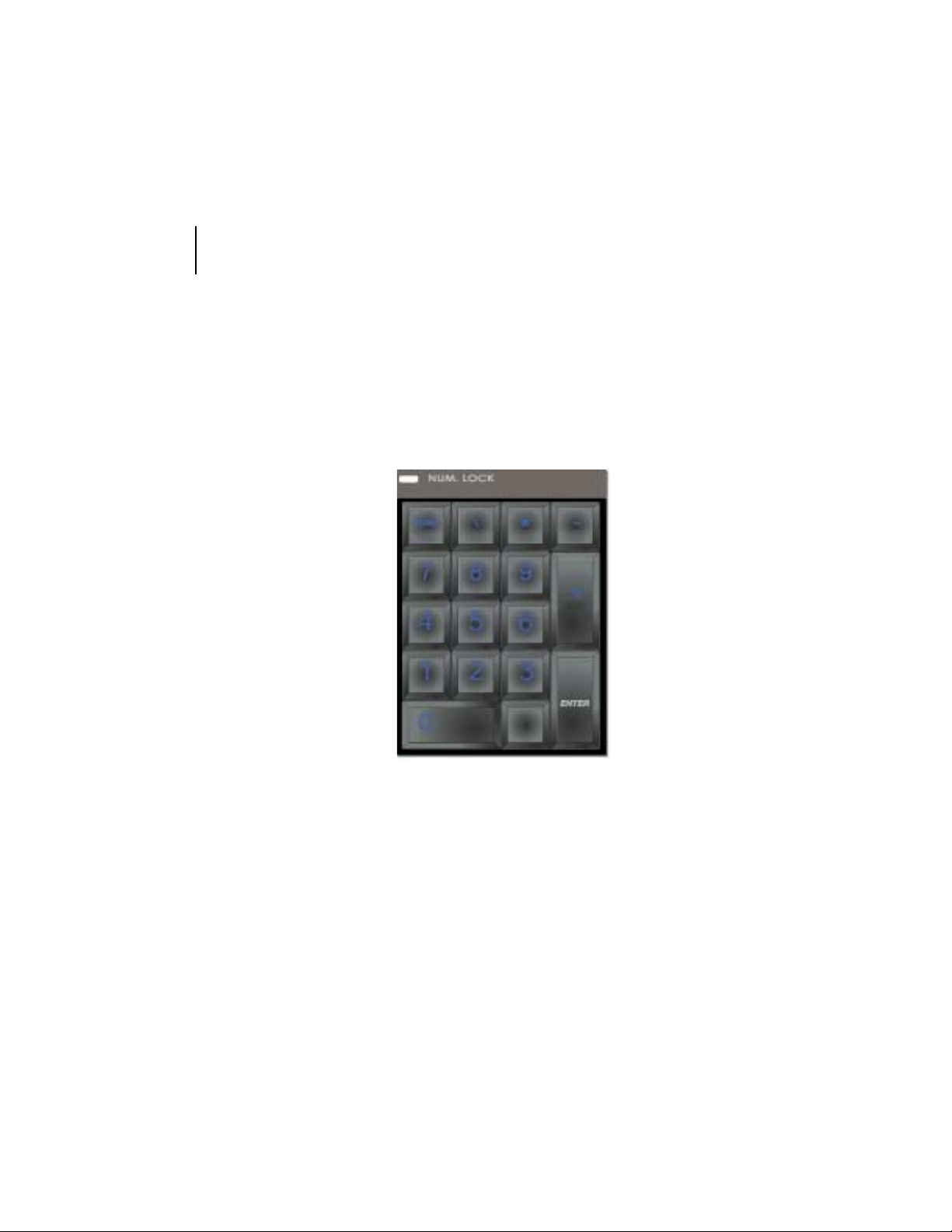
number pad
The number pad is used to trigger the numerical shortcuts.
Figure 3.3 : Num be r Pad
NOTE:
KP5YKVEJGTD[TKIJVENKEMKPICP[YJGTGKPCDKPYKPFQYCPFUGNGEVKPI
cuts
6QVWTPQPVJGPWODGTRCFUGNGEV
Numeric Shortcuts
HTQOVJGEQPVGZVOGPW
Numeric Short-
Turning this option on puts a number on every picon in a bin. You can load
any content in the bins by typing its number on the keypad and pressing
Enter. The picon you selected remains highlighted in the bin. This is useful
because higher or lower numbered picons are accessed by using the + and keys on the keypad, followed by Enter. This option is particularly useful to
those in live production environments where time is of the essence.
Page 15
control surface
user’s guide
11
fade to black
The Fade To Black button fades Program Out to black. This happens downstream of everything else inside of GlobeCaster, so it leaves effects and
graphics loaded but not showing. This gives an easy way to come back from a
commercial break with an effect still running.
Figure 3.4: Fade To Black Button
effect controls
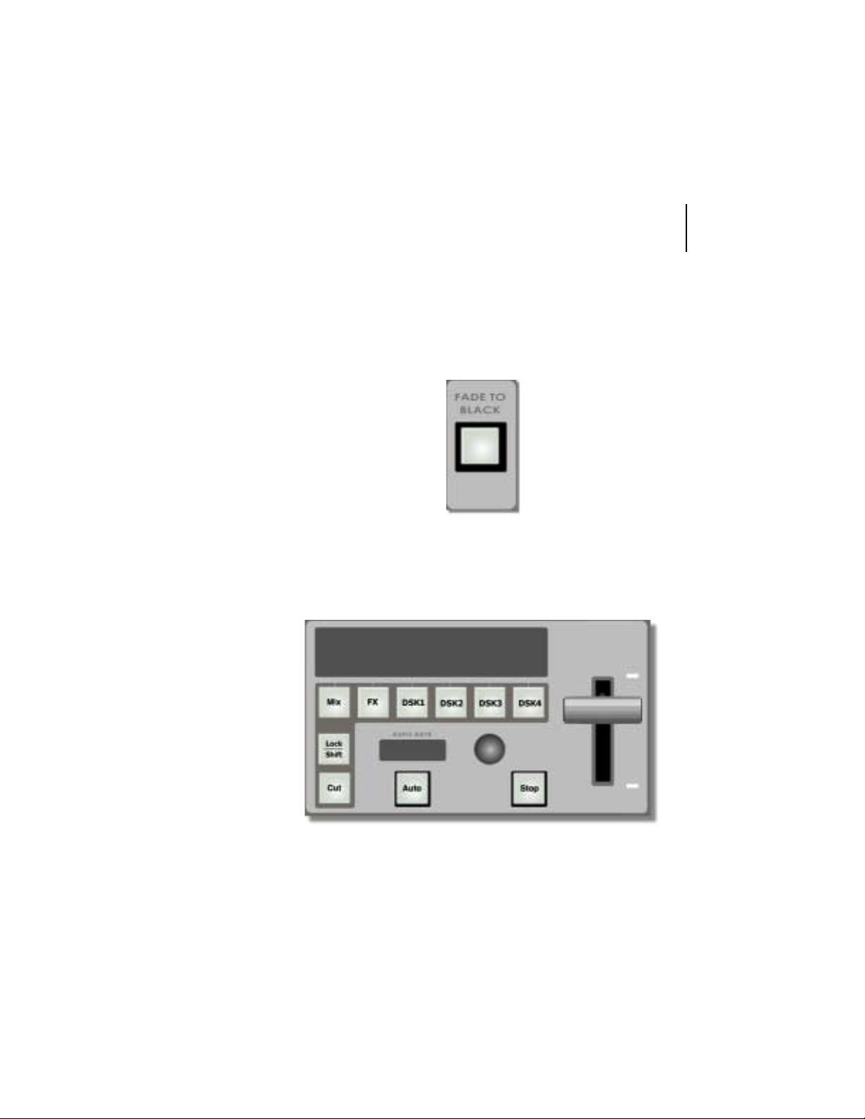
The effect controls allow you to mix the video busses.
Figure 3.5: Effect Controls
Page 16

12
chapter 3
functions
Mix When selected (lit up), you’re using a dissolve instead of an
effect.
FX When selected (lit up), clicking Auto or FX button performs
whatever is loaded as the current FX.
DSK1-4 Corresponds to your installed cards. DSK1 is your Switcher
card.
Lock When Auto is pressed, performs a cut immediately before an
effect takes place.
Cut Performs the most basic transition effect. It flip-flops the Pro-
gram and Preview busses. Whatever was on Preview is now on
Program, and vice-versa.
Auto Triggers the loaded effect. Its behavior is dependent on which
of the effect controls are selected. For example, if Mix is
selected, pressing Auto will perform a dissolve.
Some effects pause or loop in the middle of the effect. If this is
the case, click the Auto button again to end the effect.
TIP:
6QVTKIIGTC&5-QTCPGHHGEVQPVJGHN[JQNFFQYP
VJGEQTTGURQPFKPIOQFGDWVVQP
SHIFT
CPF
Stop Immediately stops any DSK or FX that has its mode button
selected (lit).
Auto
Rate
Four-character menu that displays the effect controls. This is
controlled by the rotary encoder.
effect labels
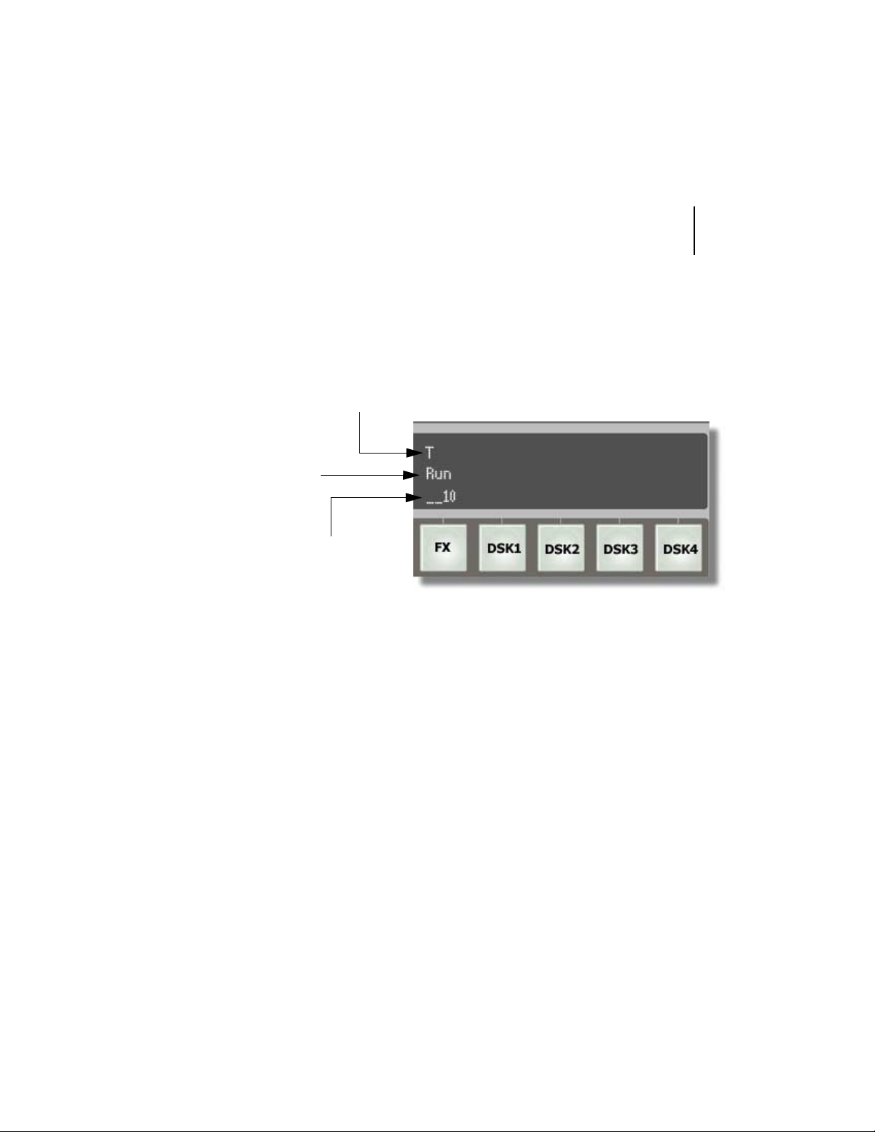
The screen area above the /KZ, (:, and &5-buttons is known as the
'HHGEV.CDGNU. They contain information relating to the currently loaded effects
and DSKs. The 'HHGEV.CDGNU contain three rows of up to four characters in
width. The basic layout of the labels is as follows:
• Property Row (top) — Shows properties of the effect.
Page 17
control surface
user’s guide
13
• Status Row (middle) — Shows which effect or DSK is running, an
asterisk in the right-most character means that particular DSK is the
default DSK.
• Length Row (bottom) — Shows a numeric value for the length of the
effect. The value represents the number of frames.
Property of
the effect
Status of
effect
Length of
effect
Figure 3.6: Effect Label Example
Property Row Shows the property or type of effect. The following
letters and words are used:
W — Warp effect
Wipe — Wipe
V — View effect
T — Transition effect
G — Gallery effect
C — Compiled effect
S — Scalable effect
L — Looped effect
Page 18
14
chapter 3
functions
Status Row Displays RUN if this effect is currently running,
otherwise, this row will be empty. An asterisk in
the fourt h ch ar acter means t h is DSK is t h e de fa ul t
DSK and effects will load to this slot by default.
TIP:
6QUGNGEVVJGFGHCWNV&5-RTGUUVJGCUVGTKUMMG[
QPVJGPWODGTRCFCPFKOOGFKCVGN[UGNGEV&5-
Length Row Displays a numerical value that corresponds to the
length of the effect in frames.
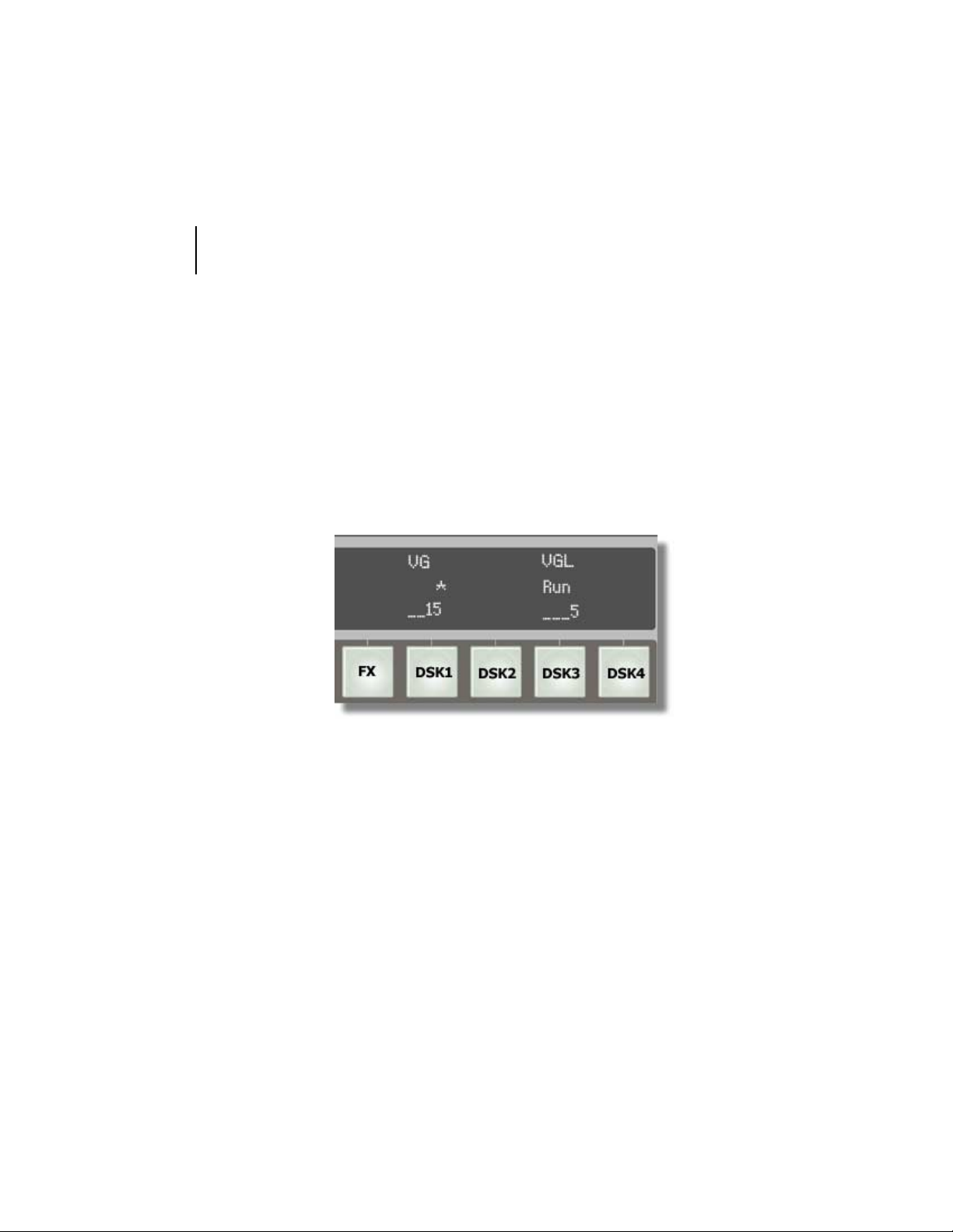
The following figure further helps to clarify the fields.
Figure 3.7: Example
In figure 3.7, DSK1 is a 15 frame View effect and also the default DSK. DSK3
is a 5 frame Looped View Effect that is currently running.
Page 19
control surface
user’s guide
15
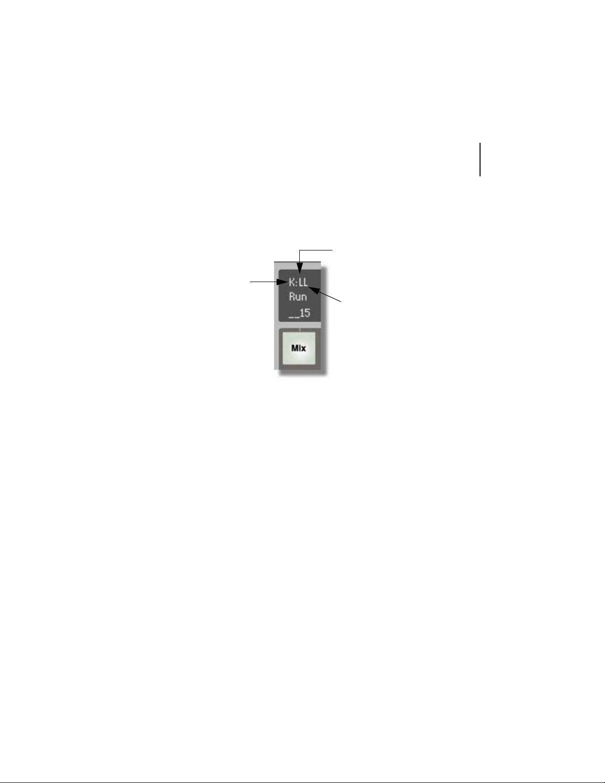
The label located above the Mix button is unique among the others. The main
difference is the Property (top) row . The top row for the Mix Effect Label represents the keyer mode.
Keyer Mode for Program. An
uppercase character means
you’re keying on Program. A
K stands
for Keyer
Mode.
Figure 3.8: Mix Effect Label
lowercase character means
you’re not keying on Program.
Keyer Mode for Preview. An
uppercase character means
you’re keying when a cut is
performed. A lowercase
character means y ou will not be
keying when a cut is performed.
The following letters are used to signify the keyer mode.
N Normal
M Mix
A Add
L Luma
E External alpha
auto rate
The rotary encoder that is located next to the Auto Rate display controls the
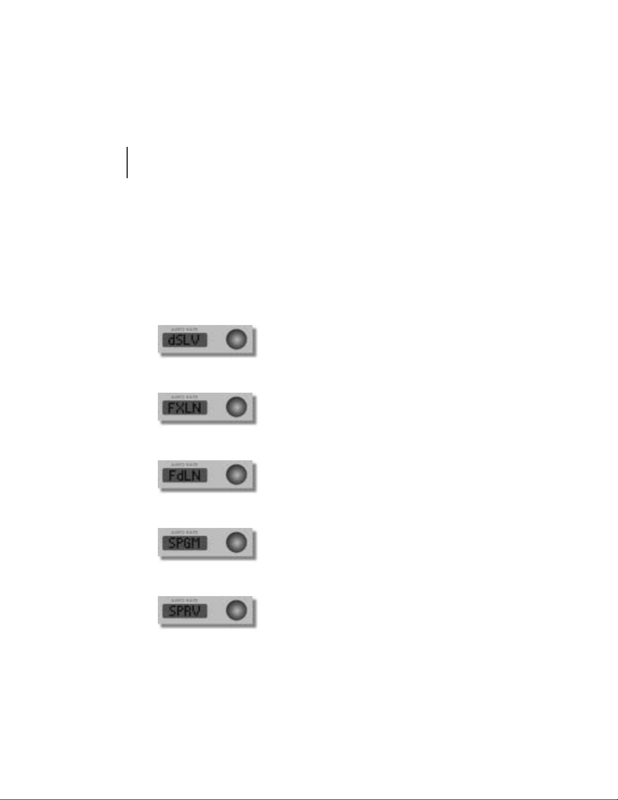
effect controls and the effect controls menu. The effect controls menu is comprised of si x different p aram eters . Le t’s take a look at the effect controls menu
and how to use the rotary encoder.
The rotary encoder can infinitely rotate clockwise or counterclockwise. Rotate
the encoder to scroll through the menu items and to change the values of
effects. To select an effect, press the encoder. The encoder acts as a toggle
Page 20
16
chapter 3
functions
button when pressed. It will toggle between a parameter and the value for that
parameter.
The following parameters all share the same numerical value scheme. To
adjust the value, rotate the encoder to your desired number. The values range
from 0 to 999, (999 is equal to 33.3 seconds in NTSC and 40 seconds in
PAL). The numbers correspond to frames, 1 is equal to 1 frame and 30 is
equal to 30 frames (or 1 second).
Dissolve Length—The dissolve length controls
the length of a dissolve.
Effects Length—The effects length determines
the length of an effect.
Fade Length—The fade length controls the length
of a fade.
Program Strobe Rate—The pr ogram strobe rate
controls the strobe rate for the program bus. This
value will be displayed in the Freeze/Strobe controls window.
Preview Strobe Rate—The preview strobe rate
controls the strobe rate for the preview bus. This
value will be displayed in the Freeze/Strobe controls window.
Page 21
control surface
user’s guide
17
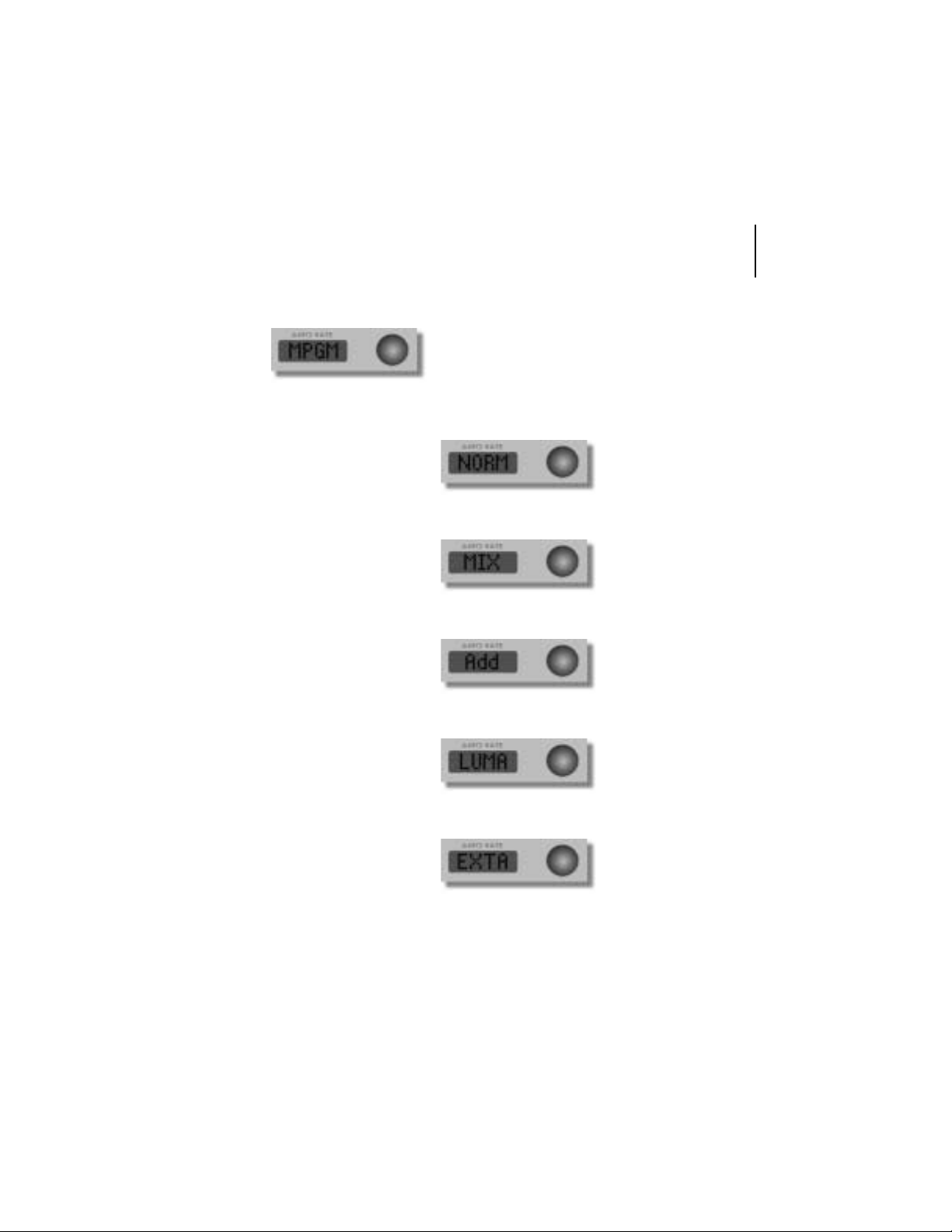
Mixer Mode (Keyer Mode) for Program—Allows
you to select a keyer mode. When this parameter
is displayed in the Auto Rate field, press the
rotary encoder to disclose the modes. To select
one of the modes, press the rotary encoder. The
following modes are available:
Normal—Overlays a
video source on top of a
key.
Mix—Performs colo r c an-
celling before keying the
foreground video.
Add—Performs color
cancelling, preserving
shadows and highlights
on the background video.
Luma—Uses luminance
to key the foreground
video.
Ext Alpha—Uses alpha
from an external source to
key the foreground video.
Page 22
18
chapter 3
functions
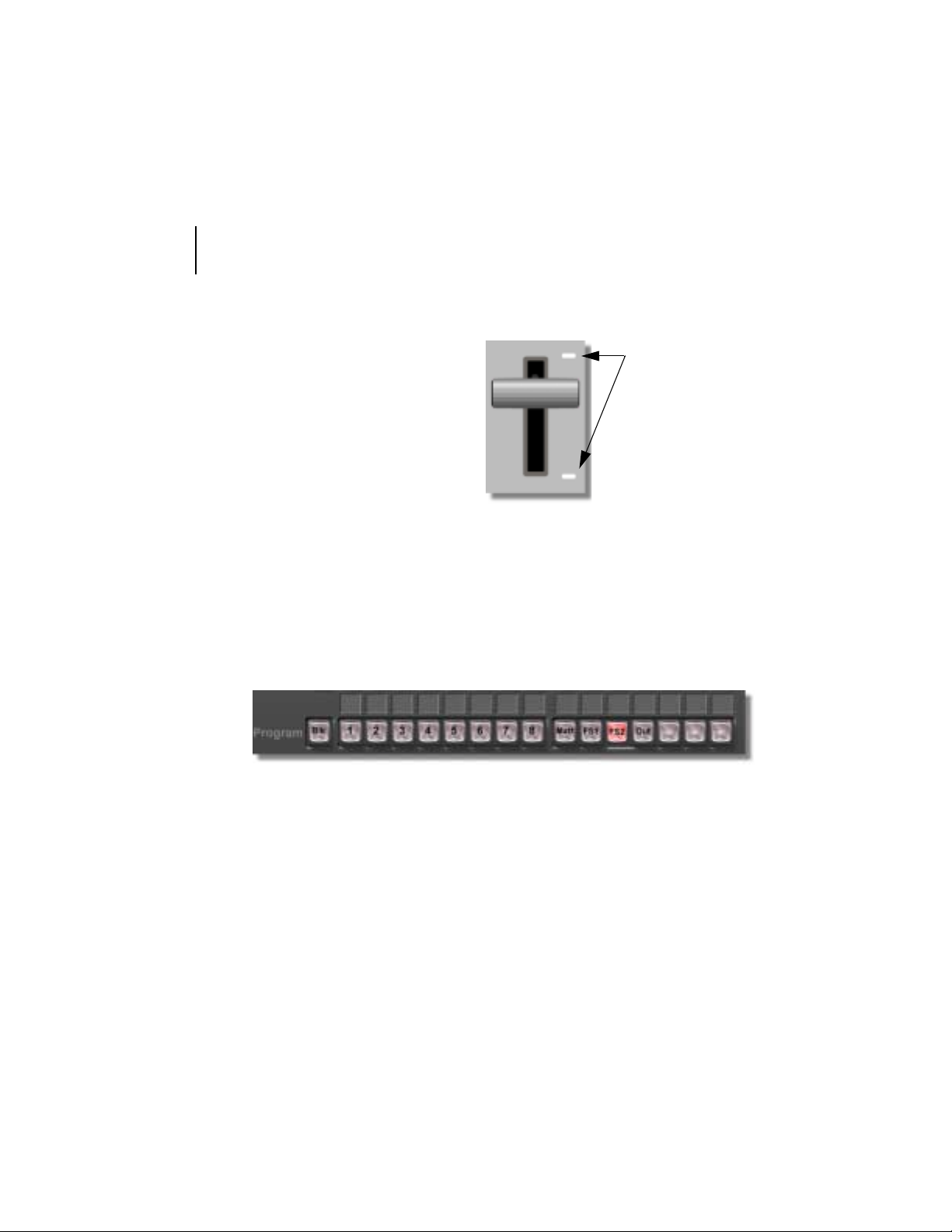
t -bar
By dragging this bar
up or down, whatever
effect or DSK is
selected is controlled
manually. The faster
the T-ba r is pulled, the
faster the effect runs.
The T -bar is espec ially
useful for pausing
midway through an
effect.
Figure 3.9: T-Bar
LEDs
You’ll notice the two LEDs to the right of the T-bar. These LEDs indicate the
polarity of the T-bar. When either of the LEDs light up, this indicates the direction that you must move the T-bar toward to finish the effect. If neither LED
lights up, this indicates that the direction has not been initalized and you must
move the T-bar to the top or bottom in order to start the effect.
soft labels
Figure 3.10: Soft Labels
Soft labels are used to identify buttons. Each soft label is comprised of two
rows with four characters in each row. You can customize each label by entering characters while in the Switcher application. Follow these steps to enter
characters into the soft labels.
1. In Switcher, (since the software emulates the layout of the CS-1000) click
on the corresponding button.
2. Enter the characters you wish to have appear in the soft label.
3. Press Enter. You will see the characters appear on the CS-1000.
Page 23
control surface
user’s guide
19
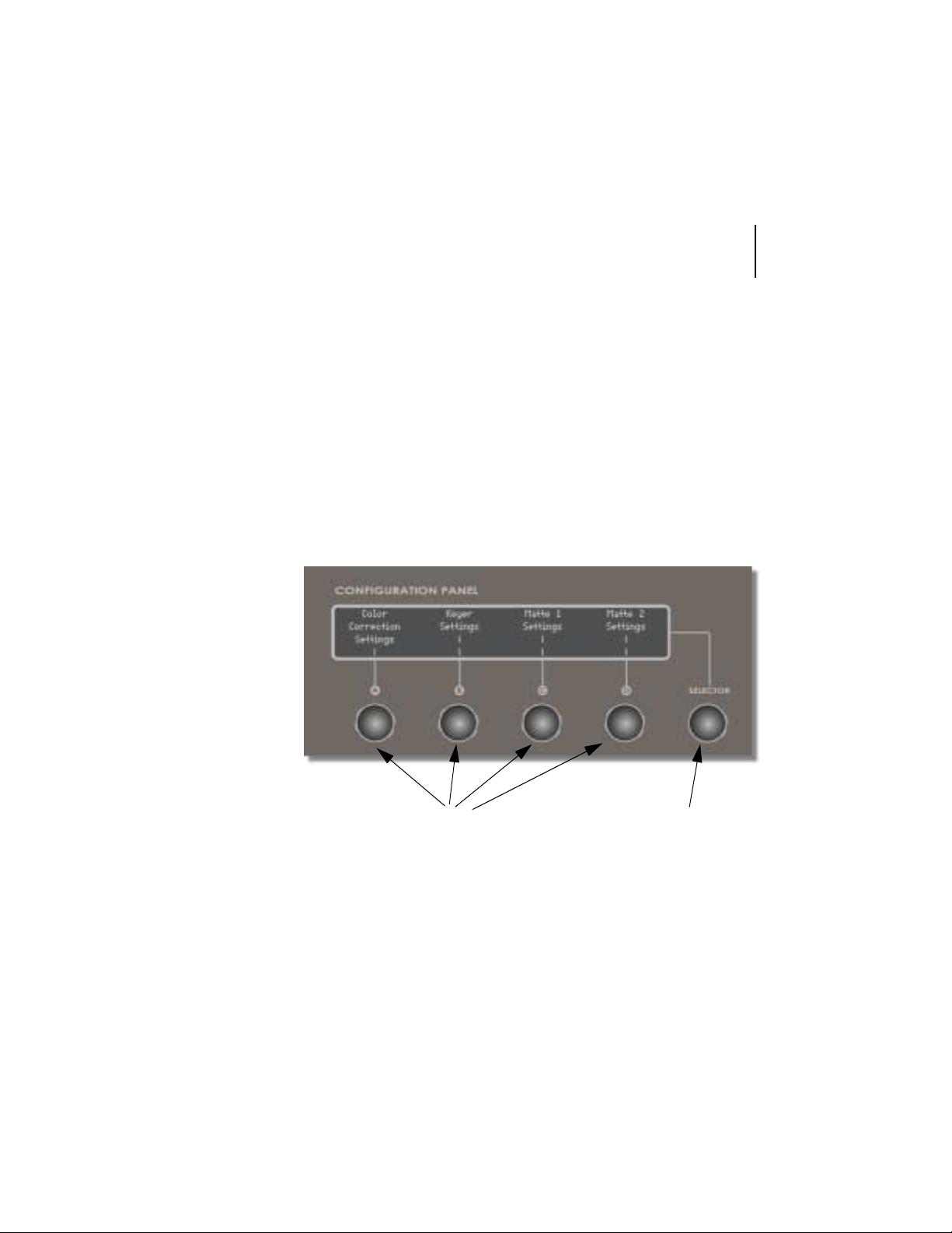
configuration panel
The configuration panel is a 4 line by 42 character VFD display with 5 rotary
encoders. From the configuration panel, you can control the following features:
• Color Correction Settings
• Keyer Settings
• Matte 1 Settings
• Matte 2 Settings
overview
Let’s take a look at the configuration panel and how the rotary encoders work
with navigating your way through the menu structure.
Rotary Encoders
Figure 3.11: Main Menu
Main Rotary Encoder
The rotary encoders have two functions. They can be turned infinitely to
change a value or they can be pressed to make a selection. The main rotary
encoder (labeled: Selector) is used to scroll through menus that require more
space than the display allows. When pressed, it is used to take you back to
the previous menu.
Page 24
20
chapter 3
functions
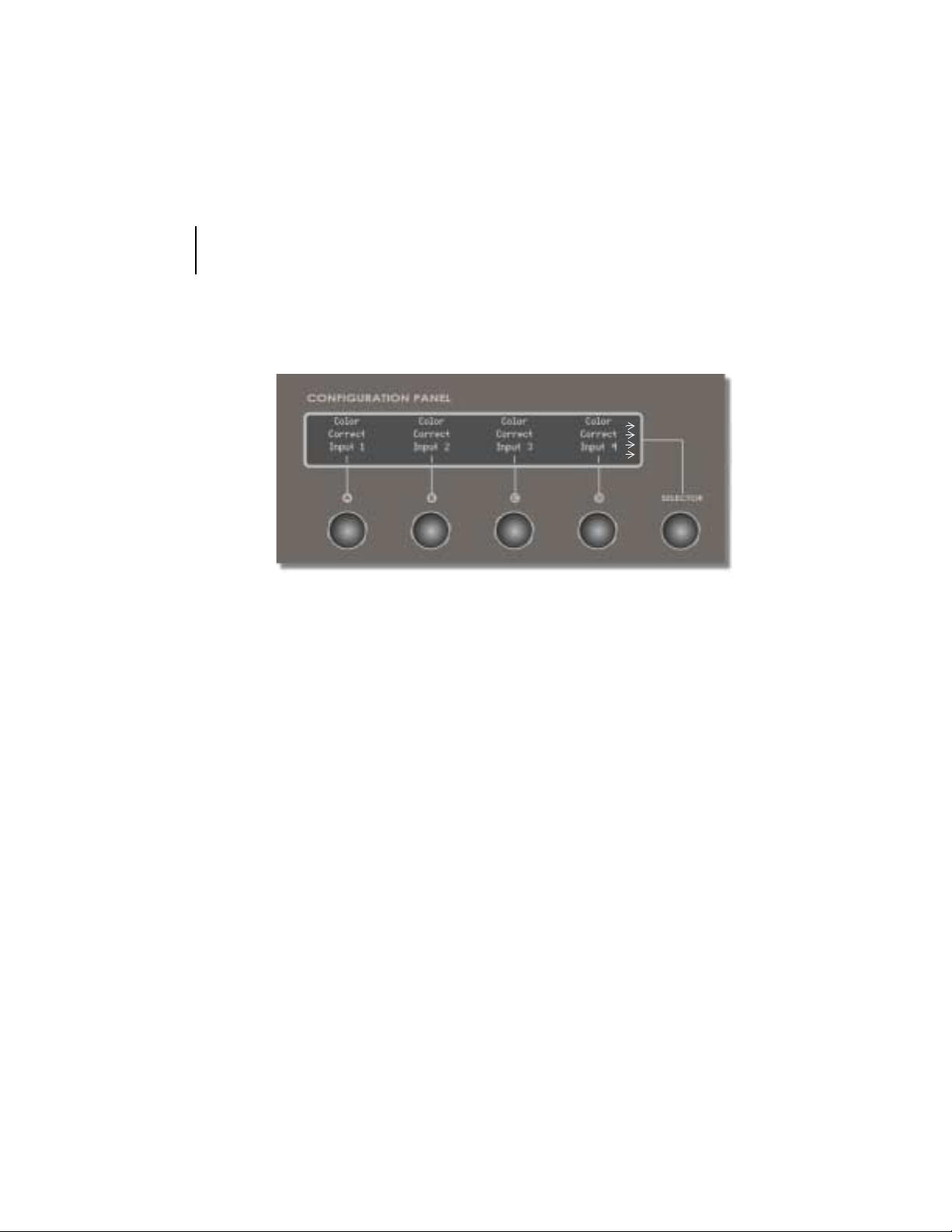
Let’s take a look at the Color Correction Settings menu; press the rotary
encoder located directly underneath the words Color Correction Settings.
The following menu is displayed.
Figure 3.12: Color Correction Se tt in gs Menu
The Color Correction Settings menu contains items that can be selected by
pressing the rotary encoder directly underneath the specific topic. Let’s take a
look at each of these items.
NOTE:
CTGOQTGOGPWKVGOUHQTVJGEQNQTEQTTGEVKQPUGVVKPIU6QXKGYVJQUGKVGOUTQVCVGVJG
Selector
GPEQFGT
0QVKEGVJGCTTQYUQPVJGTKIJVUKFGQHVJGOGPWVJKUKPFKECVGUVJCVVJGVJGTG
GPEQFGTENQEMYKUG6QTGVWTPVQVJGRTGXKQWUOGPWRTGUUVJG
Color Correct Input 1
Color Correct Input 2
Color Correct Input 3
Color Correct Input 4
Press to adjust the 1st input.
Press to adjust the 2nd input.
Press to adjust the 3rd input.
Press to adjust the 4th input.
Selector
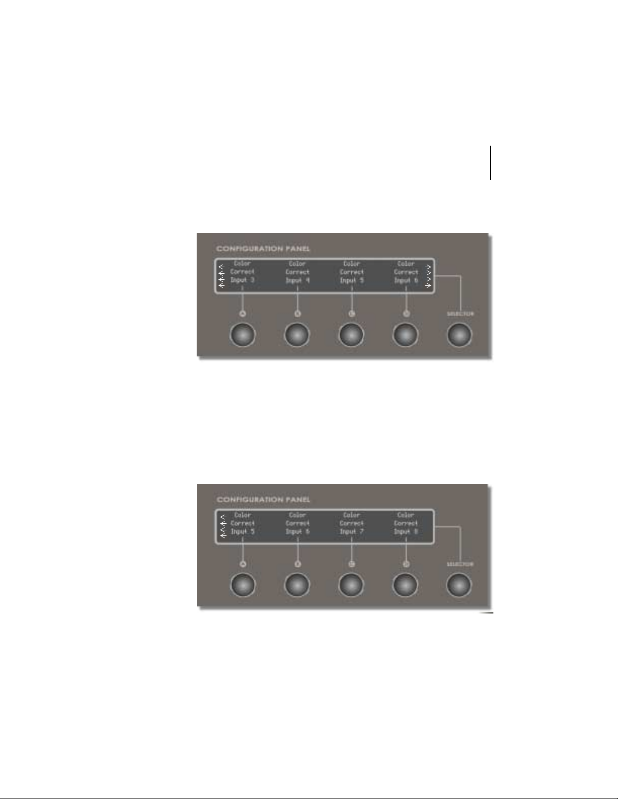
The Color Corrections menu contains additional items that are revealed when
you turn the main rotary encoder to the right. Notice in the following figure that
Page 25
control surface
user’s guide
21
arrows appear on both sides. Use the main rotary encoder to scroll to the right
to reveal more items, or to the left to display the previous items.
Figure 3.13: Color Corrections Menu Cont.
Color Correct Input 5
Color Correct Input 6
Press to adjust the 5th input.
Press to adjust the 6th input.
Figure 3.14: Color Corrections Menu Cont.
Page 26
22
chapter 3
functions
Color Correct Input 7
Color Correct Input 8
Press to adjust the 7th input.
Press to adjust the 8th input.
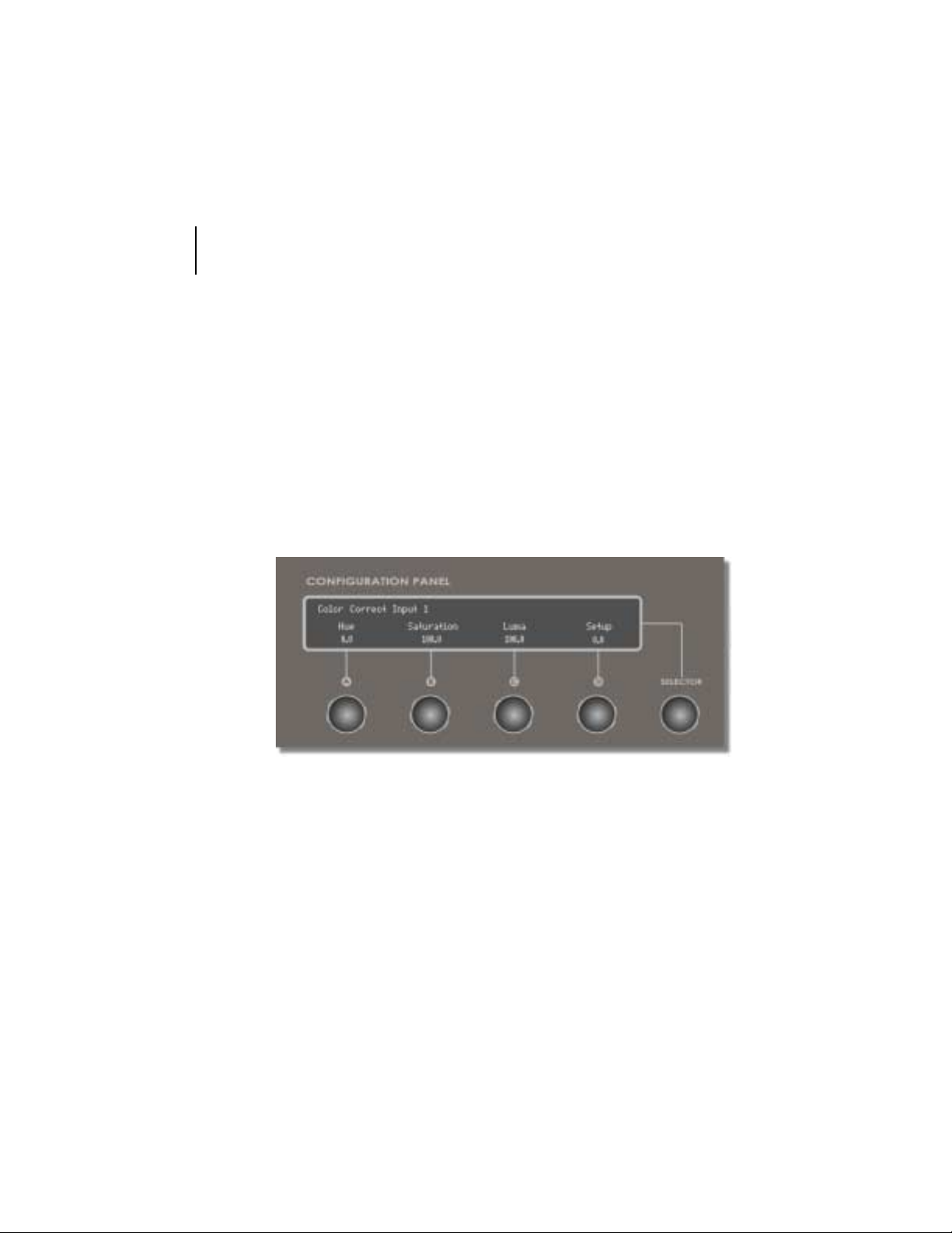
Color Correct Inputs1-8 share a similar menu that allow you to adjust the
Hue, Saturation, Luma, and Setup. However, the menu for Color Correct Input
1 will display Color Correct Input 1, the menu for Color Correct Input 2 will
display Color Correct Input 2, etc. The following image is an example of the
menu associated with Color Correct Input 1. To get out of this menu, press the
Selector encoder.
Figure 3.15: Color Correct Input Menu
Hue
Saturation
Changes the color values of the video input. If
images have an unwanted color, or hue, adjust the
Hue value to compensate for it.
Increases or decreases the amount of color, or
saturation, in the picture. If the colors seem too
vivid, lower the Saturation value. If the colors are
washed out, increase the Saturation.
Page 27
control surface
user’s guide
23
Luma
Controls the contrast of the picture. To make the
picture look sharper, increase the Luma value.
Setup
Controls the brightness of the picture. In the
broadcast industry, it is also called pedestal.
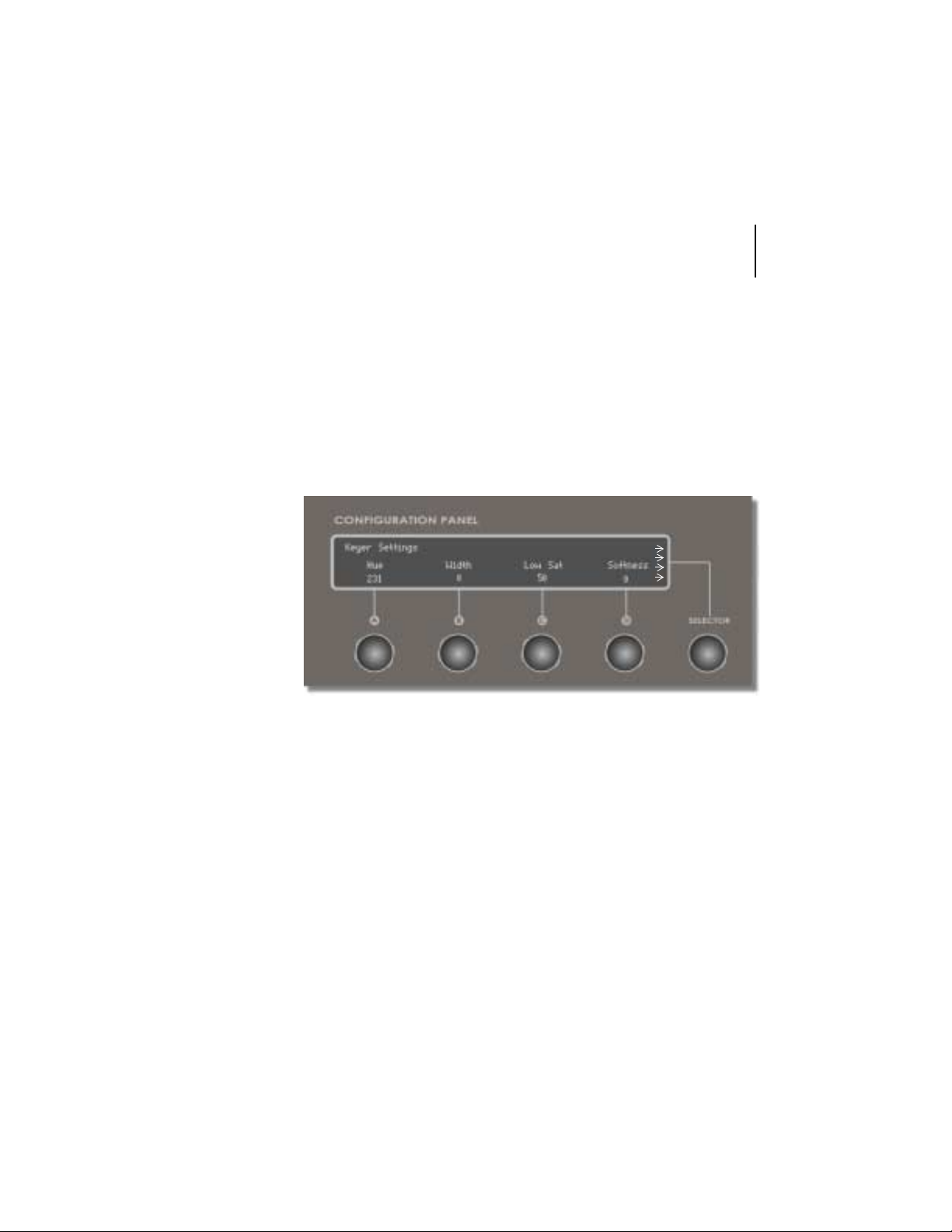
keyer settings
To display the keyer settings menu, press the rotary encoder located underneath the title, Keyer Settings. The following screen is displayed:
Figur e 3.1 6: Key e r Se t ti ngs Menu
Hue
Width
Selects the colors to be keyed out. The numbers
represent the 360 degrees of the color wheel. A
value of 1 is pretty close to chroma key blue.
Chroma key green is around 230.
Adjusts the range of color that is keyed out. If too
many shades of a certain color are removed, lowering the width value decreases the number of
shades keyed out.
Page 28
24
chapter 3
functions
Low Sat
Affects the neutral colors found in the center of the
color wheel. It acts as a circle emanating from the
center, limiting the keyer. The higher the value, the
bigger the circle and the fewer low-saturation
tones that are removed. Usually tinkered with to
remove sparkles caused by uneven lighting in a
live environment.
Softness
Smooths the edges of the areas keyed out. Set
this for a value that softens the edges of the keyed
area without adversely affecting the edges of other
parts of the image. Increasing this value too much
makes the image transparent.
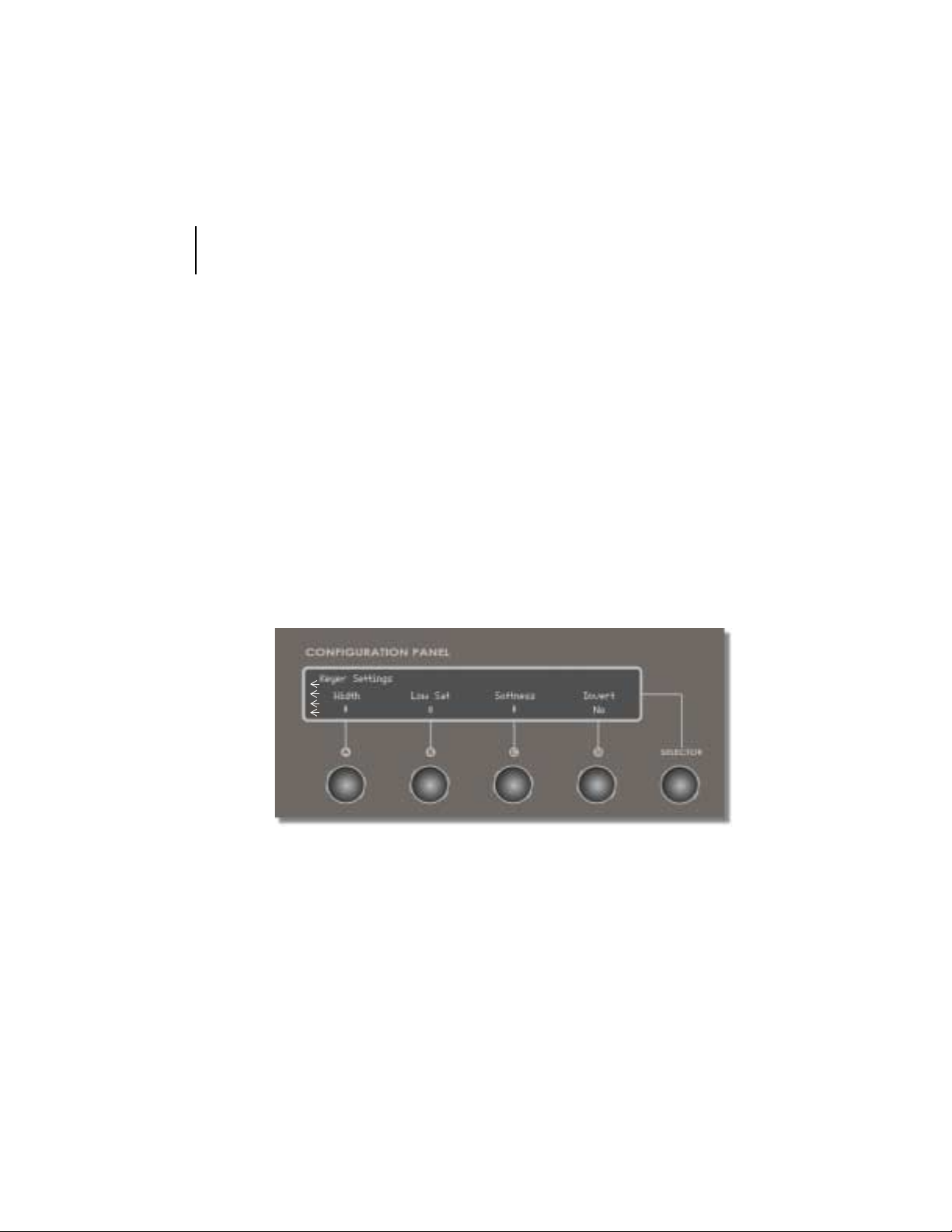
Since the Keyer Settings menu contains more items that can fit onto the
screen (as indicated by the arrows on the right) turn the Selector encoder to
the right to reveal the additional items. The following menu is displayed:
Invert
Figure 3.17: Keyer Settings Menu Cont.
Reverses the settings to form a mask around the
previously keyed areas, and the opposite of the
values selected is keyed out.
Page 29
control surface
user’s guide
25
To return to the other items in the Keyer Settings menu, turn the main rotary
encoder to the left. To return to the main menu, press the Selector encoder.
matte settings 1 & 2
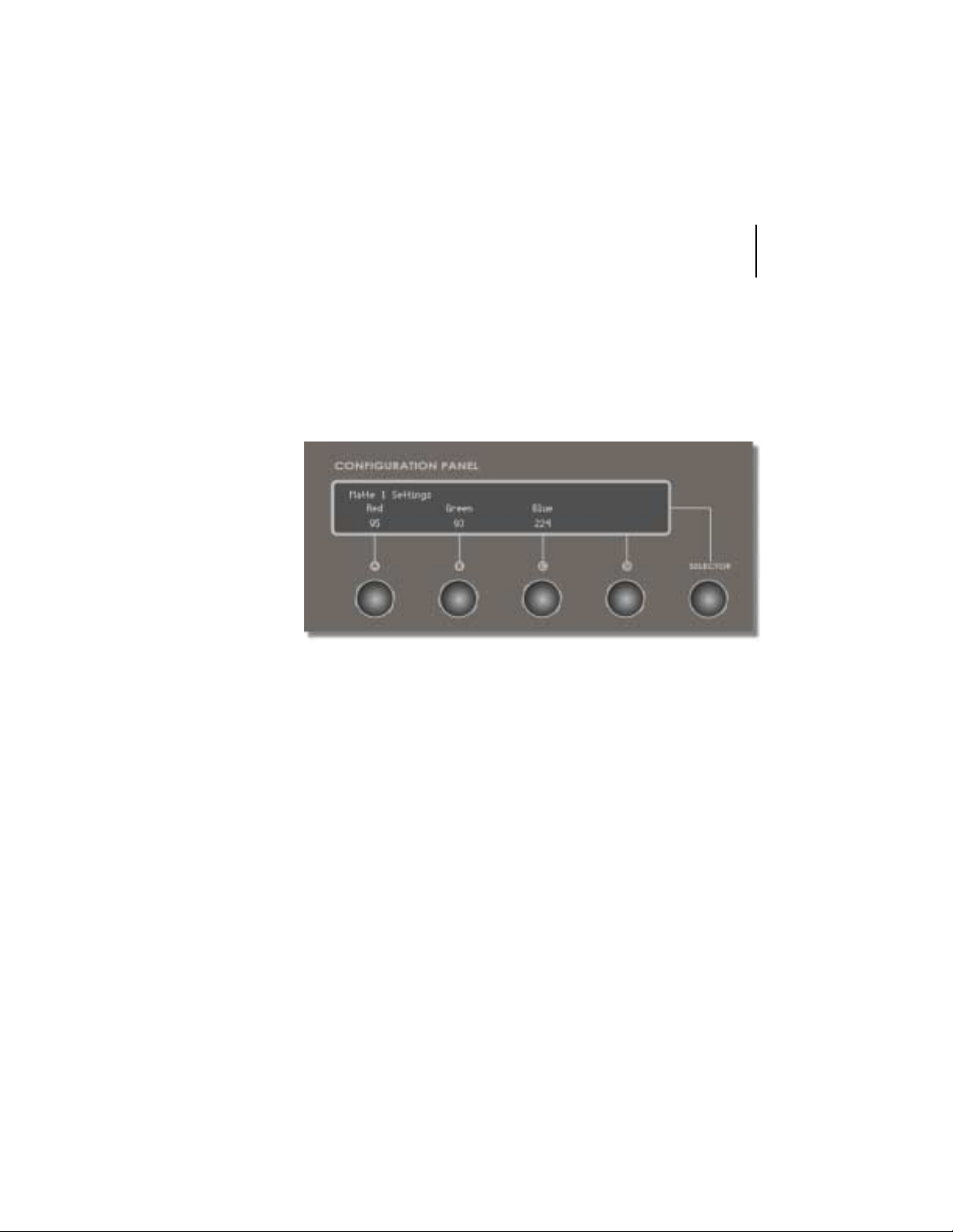
To display either the Matte 1 settings menu or the Matte 2 settings menu,
press the rotary encoder that is located directly underneath the appropriate
title. The following menu is displayed (if you selected Matte 1 Settings).
Figur e 3. 18 : Mat t e 1 Sett ings
Red
Green
Blue
Controls the amount of red in matte 1.
Controls the amount of green in matte 2.
Controls the amount of blue in matte 3.
The menu for Matte 2 Settings is the same as the menu displayed for Matte 1
Settings; however, that menu reflects the properties of Matte 2.
Page 30

26
chapter 3
functions
Page 31
chapter 4
software changes
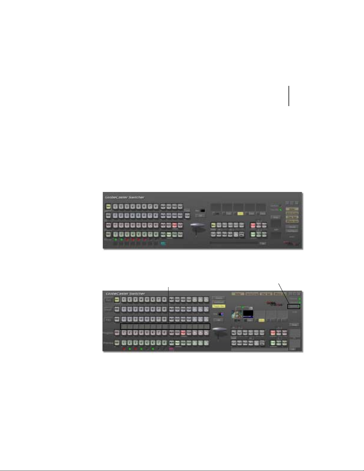
Once you install the latest version of the GlobeCaster software (and since the
CS-1000 requires 2.8 or greater ~ it’s likely that you have ), yo u’ll no t ic e som e
subtle changes to the main screen in Switcher. Let’s take a look at both the
old interface and new interface and then discuss the changes that relate to
the control surface. The biggest change you’ll find is that ce rtain ite ms have
been rearranged for efficiency, especially to match the CS-1000.
Figure 4.1: Old Switcher Interface
control surface
user’s guide
27
soft labels
Figure 4.2: New Switcher Interface
surface button
There are several changes that are covered in the GlobeCaster 2.9 Addendum. For the sake of this manual, we’ll focus on the changes that concern the
Page 32

chapter 4
28
software changes
use of the control surface: Soft labels and the Surface Button. Let’s discuss
the latter first.
surface button
The surface button is the button that allows you turn the control surface on or
off from Switcher. To turn the control surface on, right-click on the grey button
(grey indicates that the control surface is disabled) located next to the word,
Surface. The following menu is displayed:
The top portion of this menu contains the status. In figure 4.3, the control surface is disabled. To enable the control surface, drag your mouse down to
select the option: Always detect Control Surface on application startup.
Selecting this option will enable the control surface and will keep it enabled
the next time you launch Switcher.
Alternatively, you can disable the control surface and never have it detected
when you launch Switcher. To do this, right-click on the green button (green
indicates that the control surface is enabled) located next to the word, Sur-
face. The following menu is displayed:
Figure 4.3: Disabled Control Surface
Figure 4.4: Enabled Control Service
The top portion of this menu contains the status. In figure 4.4, the control surface is enabled. To disable the control surface, drag your mouse down to
select the option: Never detect Control Surface on application startup.
Selecting this option will disable the control surface (the control surface will
remain connected until you shut down Switcher) and will require you to enable
it the next time you launch Switcher.
Page 33
control surface
user’s guide
29
soft labels
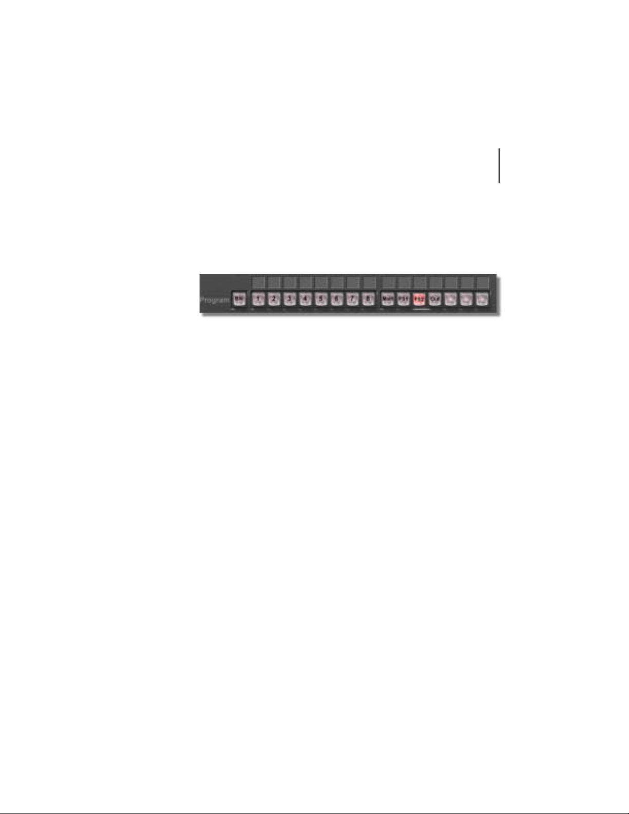
The soft labels are now located above the Program Bus (figure 4.5) and allow
you to label each button with up to four characters. While the soft labels in
Switcher aren’t new to this release, what is new is that they now control what
is displayed on the control surface.
Figure 4.5: Soft Labels
Follow the steps to label a button:
1. In Switcher, (since the software emulates the layout of the CS-1000) click
on the corresponding button.
2. Enter the characters you wish to have appear in the soft label.
3. Press Enter. You will see the characters appear on the CS-1000.
Page 34

chapter 4
30
software changes
Page 35

FCC Notice
This equipment has been tested and found to comply with the limits for a
Class A digital device, pursuant to part 15 of the FCC Rules. These limits are
designed to provide reasonable protection against harmful interference when
the equipment is operated in a commercial environment. This equipment generates, uses and can radiate radio frequency energy and, if not installed and
used in accordance with the instruction manual, may cause harmful interference to radio communications. Operation of this equipment in a residential
area is likely to cause harmful interference in which case the user will be
required to correct the interference at his/her own expense.
control surface
user’s guide
31
Page 36

32
FCC Notice
Page 37

index
control surface
user’s guide
I
A
Add, Mixer Mode 17
Auto 12
Auto Rate 12, 15
Aux Bus 8
B
Blue, Matte Settings 25
C
Color Correction Settings 20
Comm/power status lights, defi ned 9
Configuration Panel 19–25
Connections 4
Cut 12
D
Dimensions, CS-1000 2
Disabling the CS-1000 28
Dissolve Length 16
DSK1-4 12
E
Fade to black 11
Freeze, in Freeze/Strobe Controls 9
Freeze/Strobe Controls 9
FX 12
G
Green, Matte Settings 25
H
Hooking up, CS-1000 4
Hue, Color Correct Input 22
Hue, Keyer Settings 23
I
Invert, Keyer Settings 24
K
Key Bus 8
Key Preview Bus 8
Keyer Mode 17
Keyer Mode, letters 15
Keyer Settings 23
Effect Labels 12–15
Effects Length 16
Enabling the CS-1000 28
Ext Alpha, Mixer Mode 17
F
Fade Length 16
L
Length Row 13, 14
Live, in Freeze/Strobe Controls 9
Lock 12
Low Sat, Keyer Settings 24
Luma, Color Correct Input 23
Luma, Mixer Mode 17
Page 38

II
index
M
Matte Settings 25
Mix 12
Mix Effect Label 15
Mix, Mixer Mode 17
Mixer Mode 17
N
Normal, Mixer Mode 17
Number pad 10
P
Preview Bus 8
Preview Strobe Rate 16
Program Bus 8
Program Strobe Rate 16
Property Row 12, 13
letters 13
R
Red, Matte Settings 25
Rotary Encoders 19
T
T-bar 18
Technical specifications 2
V
Video Buses 7–8
W
Weight, CS-1000 2
Width, Keyer Settings 23
S
Saturation, Color Correct Input 22
Setup, Color Correct Input 23
Soft Labels 18
Soft Labels, in Switcher 29
Softness, Ke yer Settings 24
Status Row 13, 14
Stop 12
Strobe Rate, in Freeze/Strobe Controls 9
Strobe, in Freeze/Strobe Controls 9
Surface Button, in Switcher 28
 Loading...