

Page 1

Test Equipment
Users Manual
Model 3600
32 Channel Logic Analyzer
Innovative Training Solutions
www.globalspecialties.com
Model 3600 User Manual_B.indd 1 7/2/2010 4:41:38 PM
Page 2

June 2010
© 2010 Global Specialties
All rights reserved.
Specications are subject to change without notice.
All product names are trademarks of their respective companies.
Model 3600 User Manual_B.indd 2 7/2/2010 4:41:38 PM
Page 3

Table of Contents Model 3600
Introduction ������������������������������������������������������������������������������������� 1
Product Contents ................................................................................. 1
Operating Conditions .......................................................................... 1
Safety Summary ................................................................................... 1
Theory of Operation ����������������������������������������������������������������������� 2
Model 3600 Front Panel ...................................................................... 4
Model 3600 Back Panel ........................................................................ 5
Keyboard Description .......................................................................... 5
Display Control ..................................................................................... 5
Data Entry ............................................................................................. 5
Number Input ....................................................................................... 5
Input Control ........................................................................................ 6
Cursor Control and Adjust knob ......................................................... 6
Sample Rates ........................................................................................ 6
Function Selection ................................................................................ 6
Display Description ������������������������������������������������������������������������ 6
Waveform Interface Display ................................................................ 7
Data Interface Display ......................................................................... 7
Trigger Interface Settings .................................................................... 7
Operating Instructions ������������������������������������������������������������������� 7
Initialization ......................................................................................... 7
Keyboard Description .......................................................................... 8
Parameters Input ����������������������������������������������������������������������������8
Letter Input .......................................................................................... 8
Channel Setting ������������������������������������������������������������������������������9
Channel Order Setting ......................................................................... 9
i
Model 3600 User Manual_B.indd 1 7/2/2010 4:41:39 PM
Page 4

Table of Contents Model 3600
Channel Label Setting �������������������������������������������������������������������� 9
Channel Color Setting .......................................................................... 9
Channel Switch Setting ........................................................................ 9
Threshold Setting ��������������������������������������������������������������������������� 9
Sampled Signals ��������������������������������������������������������������������������� 10
Measured Signals ������������������������������������������������������������������������� 10
Display Setting������������������������������������������������������������������������������ 11
Timing Waveform Display ................................................................. 11
Waveform Rolling Up/Down ............................................................. 11
Waveform Rolling Left/Right ............................................................ 12
Waveform Zoom ................................................................................ 13
De-Compressed Waveform ................................................................ 13
Compressed Waveform ...................................................................... 13
Data Lookup - Search Function ��������������������������������������������������14
Data Listing Display ���������������������������������������������������������������������14
Cursor Setting �������������������������������������������������������������������������������15
Timing Waveform Cursor ................................................................... 15
Cursor Measurement ......................................................................... 15
Data Listing Cursor ............................................................................. 17
Sampling Setting ��������������������������������������������������������������������������17
Sampling Mode .................................................................................. 17
Clock Limitations ................................................................................ 18
Sampling Cycle ................................................................................... 19
Sampling Phase .................................................................................. 19
Sampling Control ............................................................................... 20
ii
Model 3600 User Manual_B.indd 2 7/2/2010 4:41:39 PM
Page 5

Table of Contents Model 3600
Trigger Setting ������������������������������������������������������������������������������20
Signal Input ........................................................................................ 21
Start Conditions ................................................................................. 21
Start Select .......................................................................................... 21
Trigger Conditions ............................................................................. 22
Event Count ........................................................................................ 23
Trigger Select ......................................................................................23
Store Delay ......................................................................................... 24
Manually Stop Sampling Process ....................................................... 24
Trigger Cursor .....................................................................................24
Save/Recall������������������������������������������������������������������������������������25
Parameter Storage ............................................................................. 25
Waveform Storage ............................................................................. 25
Cancel Storage ................................................................................... 26
Recall ................................................................................................... 26
Reset ................................................................................................... 26
Programmable Interface ��������������������������������������������������������������26
Remote Update �����������������������������������������������������������������������������26
Specications �������������������������������������������������������������������������������27
Service ������������������������������������������������������������������������������������������� 30
Warranty ............................................................................................. 30
Non-Warranty Service ........................................................................ 30
iii
Model 3600 User Manual_B.indd 3 7/2/2010 4:41:39 PM
Page 6

Users Manual Model 3600
Introduction
Congratulations on the choice of Global Specialties Model 3600. This
32 channel Logic Analyzer observes and measures digital signals in
digital information processing. It captures and displays many signals at
once, and analyzes their timing relationships. Use its internal clock, or
connect up to 2 external clocks for sampling rate variability. This logic
analyzer will prove to be a versatile tool to help in digital hardware
debugging and verifying circuit designs. Model 3600 operates as a
stand-alone unit or connected to a computer via USB interface.
Product Contents
Model 3600 Mainframe
Users Manual
1 ea 3-core power line
2 Sets of 50 wires cables and connector
2 ea Input transferring boxes
40 ea Test hooks
40 ea Test hook connecting lines
1 ea Interface demo CD
1 ea USB interface cable
1 ea RS232 interface cable
Operating Conditions
Input Power Voltage: AC 100V~240V
Frequency: 45 Hz ~ 65 Hz
Power: <30 VA
Environmental Conditions: Temperature: 0~40°C
Relative Humidity: ≤80%
No powerful electromagnetic interference
Safety Summary
1) Review the following safety precautions to avoid injury and
prevent damage to this product or any products connected to it.
To avoid potential hazards, use this product only as specied.
2) Only qualied personnel should perform service procedures.
www.globalspecialties.com Page 1
Model 3600 User Manual_B.indd 1 7/2/2010 4:41:40 PM
Page 7
Users Manual Model 3600
3) Use Proper Power Cord. Use only the power cord specied for
this product and certied for the country of use.
4) Ground the Product. This product is grounded through the
grounding conductor of the power cord. To avoid electric shock,
the grounding conductor must be connected to earth ground.
Before making connections to the input or output terminals of
the product, ensure that the product is properly grounded.
5) Observe All Terminal Ratings. To avoid re or shock hazard,
observe all ratings and marking on the product. Consult the
product manual for further ratings information before making
connections to the product.
6) The common terminal is at ground potential. Do not connect
the common terminal to elevated voltages.
7) Do not apply a potential to any terminal, including the
common terminal, that exceeds the maximum rating of that
terminal.
8) Use Proper Fuse. Use only the fuse type and rating specied
for this product.
9) Do Not Operate With Suspected Failures. If you suspect there
is damage to this product, have it inspected by qualied service
personnel.
10) Do Not Operate in Wet/Damp Conditions.
11) Keep Product Surfaces Clean and Dry.
12) Provide Proper Ventilation.
Theory of Operation
To sample an external signal source, the external signal is sent into
the positive input port of the high-speed comparator via the input
circuitry. The threshold circuit generates a threshold voltage according
to the set values, and sends the voltage to the negative input port of
the high-speed comparator. A TTL level digital signal is generated by
the comparison of the 2 signals and then the digital signal is stored
synchronously in the data ip-latch by sampling clock. When sampling
the internal code, the code generator will produce 30 channels of
internal digital signals which are stored synchronously in the data iplatch by sampling clock. The sampling data in the data ip-latch are
www.globalspecialties.com Page 2
Model 3600 User Manual_B.indd 2 7/2/2010 4:41:40 PM
Page 8

Users Manual Model 3600
stored in high-speed memory according to appointed addresses.
Selecting the internal clock timing sampling will set the cycle of the
sampling clock. State sampling with the external clock will select the
phase of the sampling clock.
During the sampling storage period, a “sequence add 1 counter ”
supplies the storage address for the high-speed memory in the memory
control circuit, each sampling clock makes the memory change to a new
writing address. At the same time the ip-latch sends new sampling
data, creating a new data point stored in memory. The start-up and
end of the address counter is determined by the memory control
circuit according to the parameters set by the triggering process. After
sampling storage, the microcontroller unit reads a series of data and
sends them to the LCD to display the timing waveform and data list.
www.globalspecialties.com Page 3
Model 3600 User Manual_B.indd 3 7/2/2010 4:41:40 PM
Page 9
Users Manual Model 3600
3600 LOGIC ANALYZER
MODEL
CH15 - CH0CLK1CH31 - CH1 6CLK2
FUNCTI ON
WV X Y
Z
U
Q R S T
NM
I J K L
PO
E F G H
ADJ UST
DATA E NTRY
A B C D
Channel
shr ldT oeh
System
Tri gger
Si ng l e
Run/
St op
Rec al lSaveSource
Ti me/
State
ay
sp
lDi
?
?
?
Fi nd
Zoom
7
4
1
0 x
aegan ugL
Shi f t
∩
98
5 6
32
Cur s o r
1
Cur s o r
2
Reset
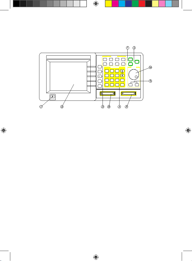
Model 3600 Front Panel
1))ON / Off power switch
2))Display screen
3))Display control pushbuttons
4))Data entry input pushbuttons
5))Cursor control pushbuttons
6))Sample rate pushbuttons
7))Function Selection pushbuttons
8))Signal input connector, Channels 0 through 15
9))Signal input connector, Channels 16 through 31
10) Cursor Adjust knob
www.globalspecialties.com Page 4
Model 3600 User Manual_B.indd 4 7/2/2010 4:41:42 PM
Page 10
Users Manual Model 3600
AC 100-240V 1A
REPLACE FUSE
AS SPECIFIED
DISCONNECT POWER CORD
BEFORE REPLACING FUSE
USB RS-232
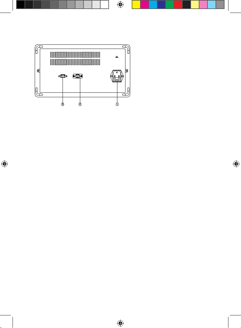
Model 3600 Back Panel
1)AC power source outlet
2)RS232 interface
3)USB device interface
Keyboard Description
There are 34 pushbuttons on the front panel divided into these groups:
Display Control, Function Selection, Data Entry, Cursor Control, and
Sample Rates.
Display Control
Display: display timing waveforms or data lists in cycle.
↑ ↓: use the knob to roll timing waveforms and data lists up and down
← →: use the knob to roll timing waveforms and left and right
Zoom: use the knob to zoom timing waveforms
Find: nd and display the data points suited the search conditions
Data Entry
(11 pushbuttons for Number input, 4 pushbuttons for Input control, 1
pushbutton for Language)
Number Input:
【0】【1】【2】【3】【4】【5】【6】【7】【8】【9】: number input;
【x】: special characters x, only used for data search input
www.globalspecialties.com Page 5
Model 3600 User Manual_B.indd 5 7/2/2010 4:41:43 PM
Page 11

Users Manual Model 3600
Input Control
【↑】【↓】: select the setting parameters up to down in cycle
【←】: backspace, to delete the input data when the input hasn’t
nished
【Shift】: used for inputting the English letters above the button
【Language】: English only
Cursor Control and Adjust knob
【Cursor 1】: use the knob to move the cursor1 left and right
【Cursor 2】: use the knob to move the cursor2 left and right
Sample Rates
Run/Stop: circular run/stop recycling sample
Single: single sample
Reset: initialize the instrument and resume the default
parameters settings
Function Selection
Channel: select and set the sequence order, name, color and
switch of each channel in cycle.
Threshold: select and set the threshold voltage.
System: select and set the system parameters.
Trigger: select and set the parameters and the switch in the
trigger process.
Time/State: select the mode of timing sample or state sample in
cycle
Source: select internal code generator or external signal source
in cycle.
Save: save the current setting parameters.
Recall: recall the last saved setting parameters
Display Description
The top row of the display screen indicates chosen function. There are 3
types of display interface described below.
www.globalspecialties.com Page 6
Model 3600 User Manual_B.indd 6 7/2/2010 4:41:43 PM
Page 12

Users Manual Model 3600
Waveform Interface Display
The Waveform Interface displays 8 channels of timing waveforms,
the serial number and the name of the waveform and includes four
different vertical cursor lines in varied colors. There is one scale on the
top of the waveform frame, and another one is on the bottom of the
waveform frame. These are the zoom scales. The time value of every
scale varies with the zoom coefcient. Below the waveform frame
is the parameters display frame, the six parameters on the left is the
state parameters which varies automatically with different operations,
showing the current state of the equipment. The six parameters on the
right is the parameters settings of the system and can be set with the
numeric pushbuttons.
Data Interface Display
The data interface displays 19 rows of data. Each row is one sampled
data point in memory, corresponding to 32 sample channels. The three
columns of data from left to right is the address of data, the data
value in Decimal (Dec), the data value in Hex, the data value in Binary
(Bin). The parameters display frame is below the data lists frame, the
three parameters on the left are the state parameters which changes
automatically with different operations, showing the current state
of the instrument. The 2 parameters on the right are the parameters
settings of the system and can be set with numeric pushbuttons.
Trigger Interface Settings
The trigger interface displays the whole trigger process. It utilizes a
graphical display mode to easily illustrate the entire triggering process.
The panes in the display interface are the nodes of the trigger process.
The connecting lines among the panes show the direction of the trigger
process, six parameters can be set on the right, the left side has six
switches for setting. The specications of these settings are explained
later in this manual.
Operating Instructions
Initialization
Turn on the Model 3600 using the front panel ON/OFF pushbutton. The
model number and the manufacturer of the instrument will rst be
seen on the display. Operate the initialization program by loading the
www.globalspecialties.com Page 7
Model 3600 User Manual_B.indd 7 7/2/2010 4:41:43 PM
Page 13

Users Manual Model 3600
default parameter settings. Next the timing waveforms of internal code
will be displayed.
Most of functions performed by the logic analyzer are single or non-
cyclical signals included in high speed data streams. The analyzer can’t
display the signals in real-time on the screen as an oscilloscope would,
but it can sample the signals according to certain time rate (sample
clock). The analyzer will catch and save any signal anomalies by setting
up the appropriate trigger process. The saved data can be recalled onto
the screen and analyzed repeatedly.
Keyboard Description
When any pushbutton is pressed, there is a corresponding display on
the screen which explains the function and its operation. If there is a
circular symbol, consisting of two arrows laid end to end, on the left
of the explanation then it is a cycle key. It runs different functions by
pressing it repeatedly. If there is no circular symbol, the pushbutton has
only one function.
Parameters Input
If there are reverse numbers or characters displayed on the screen, this
means the parameter is a selected one which can be set by pressing
the pushbutton. If the user needs to select other data, 【↑】and【↓】
can be used. The user also can turn the knob left and right to select
other cyclical data. If a wrong character or number is input, the user
can delete the one by pressing【←】. As soon as the reverse character
areas are lled with numbers, the parameter settings take effect. At
this point the【←】will no longer work, unless the input process is
restarted.
Letter Input
The 26 letters, from A to Z, are marked above 26 keys on the front
panel. During the process of parameter input, press the【shift】key,
release the shift key, then input the letter desired. If there is no letter
on the key, the user can input a space. The【shift】key is a single step.
In order to input the next letter, the process above is to be repeated.
www.globalspecialties.com Page 8
Model 3600 User Manual_B.indd 8 7/2/2010 4:41:43 PM
Page 14

Users Manual Model 3600
Channel Setting
Channel Order Setting
The double digit numbers 00-31 on the left side of the waveform
display frame are the serial numbers for each channel. Press【Channel】
key to select the channel serial number setting. Then set the channel
sequence using the numeric keys. The settings only change the position
of channel waveforms on the screen so that different channels of
waveforms can be closely displayed and easily compared. However
the real positions of sampling channels and the sampled data are
not changed. If the real positions of sampling channels need to be
changed, the user needs to change the connection of the test hooks for
sampling on the circuit board.
Channel Label Setting
The four characters on the right of the channel serial numbers are the
label of the channel. Press【Channel】key to select the channel label
setting. Set the channel label by using the numeric keys or letter keys.
Every channel label can be set by the user.
Channel Color Setting
Press【Channel】key to select the desired channel color setting. Set
the color using the numeric keys. Every channel can be set according to
user’s choice of color.
Channel Switch Setting
Press the【Channel】 key to select channel switch setting. Set the
channel “on” by using the numeric key【1】. Set the channel “off” by
using the key【0】. The settings will take effect in the process of next
sampling display.
Generally, the settings of the channels are not required to be changed
often. Press【Save】to save the dened channel settings to re- use then
without having to reset the settings.
Threshold Setting
Press the【Threshold】key to set the threshold voltage setting. The
【↑】and【↓】pushbuttons are used to circularly select one of the
six threshold voltages. Only the knob can be used to set the value
of threshold voltages in a continuous manner (numeric keys can’t
www.globalspecialties.com Page 9
Model 3600 User Manual_B.indd 9 7/2/2010 4:41:44 PM
Page 15

Users Manual Model 3600
be used). The voltage will increase by turning the knob to right and
decrease by turning the knob to left. When the voltage value passes
the zero, the polarity sign will automatically change. The internal
code-generator doesn’t pass the voltage comparator, so the settings on
threshold voltage aren’t valid when sampling the internal code.
The analyzer has 32 external signal input channels and 2 external
clock channels. The best performance is when the peak-to-peak value
of input voltage is between 500 mVpp and 20 Vpp. The maximum
input voltage the instrument can handle is ±40 V. After accessing the
analyzer, the input signal rst passes through the voltage comparison
circuit and is compared with the threshold voltage set by the user. If the
input signals are higher than the threshold voltage, the analyzer shows
the number “1”, otherwise it displays the number “0”. Then the signals
are sampled and saved and displayed on the screen.
Waveforms displayed by this means only reect the timing logic when
the input signals are higher or lower than the threshold voltage. It
doesn’t reect the real amplitude of the input signals, and may be far
different from the real waveforms of the input signals. This kind of
waveform displayed by the logic analyzer is usually called a “pseudo
waveform”.
Sampled Signals
In practical operation, the sampled signals appear by groups.
For example, grouped by the data bus or the address bus .The
characteristics of amplitude of a group of signals are the same, so use
the same compare threshold voltage. The amplitude characteristics of a
group of signals are the same, so use the same comparative threshold
voltage. In practical operation there are many kinds of signals with
different amplitudes to be tested, such as TTL, CMOS and ECL. In every
experimental circuit, the amplitude characteristics of signals may be
various. To satisfy these conditions, the instrument is deployed with
six individual adjustable threshold voltages. Four of them are used in
four channel groups which contain 8 signal input channels in each one.
And the other 2 threshold voltages are used in 2 external clock input
channels.
Measured Signals
In practice, the instruments measures signals in groups, for instance
www.globalspecialties.com Page 10
Model 3600 User Manual_B.indd 10 7/2/2010 4:41:44 PM
Page 16

Users Manual Model 3600
in the total line and address line. The amplitude characteristic of
one group is identical and should also use the same comparison
threshold voltage. However the instrument has 32 signal input
channels and again, it is not necessary to setup 32 independently
adjustable threshold voltages. But in practice, there are measured
signals with different amplitudes for instance TTL, CMOS, and ECL. In
many experimental circuits, the amplitudes required may vary. For this
application, six independently adjustable threshold voltages can be
congured, four of which are used for four channel groups, each group
has 8 signal input channels. The other 2 are used for 2 external clock
input channels separately.
In practice, the voltage amplitudes of +5 V or +3.3 V are commonly
used in a digital circuit. Model 3600’s default settings of the threshold
voltage are at +1.6 V. Generally, the setting range of the threshold
voltages for TTL is between +5V and +3.3V. The setting range of
threshold voltages for CMOS is between +5V and +4.3V. If the tested
signals contain large ringing effects or other voltage noises, there will
be extraneous data in the sampled results. If this happens, repeat the
sampling function to adjust the threshold voltage and observe the
sampling waveforms, until clear and correct sampling waveforms are
obtained.
Display Setting
The 3600 logic analyzer can display a vast amount of data. There are
two display modes of sampling data: timing waveform display and data
listing display.
Timing Waveform Display
Press【Display】to view timing waveforms for up to 8 channels. Each
channel can be displayed with different colors to easily identify and
separate them visually. The order of 32 channels waveforms is that the
highest channel is on the top and the lowest channel is at the bottom.
This is to enable the highest-order digit of the byte to be on the top
and the lowest-order digit on the bottom.
Waveform Rolling Up/Down
The waveform rolling can be used to observe all the waveforms in 32
channels. Press【↑ ↓】and turn the knob to browse the waveforms.
www.globalspecialties.com Page 11
Model 3600 User Manual_B.indd 11 7/2/2010 4:41:44 PM
Page 17

Users Manual Model 3600
If there is a need to compare the waveforms, the method of channel
order setting (see Channel Order Setting) can be used to display the
desired waveforms.
Waveform Rolling Left/Right
The Model 3600 allows for 260,000 memory addresses for each
channel, however only 280 data points can be viewed due to the
horizontal width of the screen. In order to display the needed blocks
from the mass of stored data, the screen display window needs to be
repositioned to the desired data in memory. This requires setting a
changeable “window address” for the display window. The screen of
the analyzer will show the stored data block using this new window
address as starting point.
The parameter in the rst row on the right bottom of the wave frame
is the window-address. The waveform displays the data on the most
left, that is the data corresponding to the window address in sampling
memory. Press【System】to select window-address and set the window
address in Dec numbers with the range of 0~260000. After setting,
the waveform of sampled stored data block associated with this new
window address will be displayed. To continuously observe a waveform
on the display, press【← →】 and turn the knob. The window-address
will change continuously showing the waveform rolling from left to
right in the display window.
The parameter in the second row on the right bottom of the wave
frame is a scroll-step function. Turn the knob one step and the windowaddress will increase one scroll-step value. The higher the value of
scroll-step, the faster the speed of the rolling waveform. This could
possibly surpass the desired data block. The lower the value of scrollstep, the slower the speed of rolling and the ner observation of the
waveforms. Press【System】to select scroll-step. The value of the scroll-
step can be set by using the number keys with the range of 1~ 260 000.
After setting, press【← →】 and turn the knob to roll the waveform
left and right, so that the speed of rolling waveform will change.
Setting the window-address using the number keys directly enables
display window to locate the desired sampled block of data. Rolling
waveforms utilizing the knob allows observation of section changes in
a continuous manner.
www.globalspecialties.com Page 12
Model 3600 User Manual_B.indd 12 7/2/2010 4:41:44 PM
Page 18

Users Manual Model 3600
Waveform Zoom
In digital systems, changing rates of different logic levels can vary
within different data channels. When trying to view these on the
display, it is possible to have 8 channels with big differences in the
changing rates of logic levels. This can cause viewing problems due
to the large number of pulse waveforms crowded together on the
screen and the fast changing logic level rates will not be seen clearly.
Conversely, if a channel has slow changing rates, it becomes a at line
on the screen. To solve these two visual problems, either stretch the
waveforms in level direction to de-compress and unfold the crowded
fast-changing pulse waveforms. Or compress the slow-changing
waveforms to easier view their characteristics.
De-Compressed Waveform
Press the【Zoom】key and turn the knob to make the display
waveforms stretch or compress in the horizontal direction. “Zoom= ns/
div” in the sixth row on the left bottom of the wave frame will change.
This ratio coefcient stands for the time increment that each lattice
of scale line represents both in the above and underside two rows
of waveform frame. The essence of waveform amplication is that a
number of sampled data points in memory are displayed continuously.
The amplied waveform allows dense waveforms to be viewed
more clearly. This does not generate any distortion to the waveform.
However waveform amplication is unable to increase the resolution.
Unsampled data points will still not be seen after amplication. If
it is desired to see in more detail, then it is required to increase the
sampling velocity.
The waveform zoom function uses the sampling clock as its time unit. If
the user needs to measure the interval of the waveform accurately, it is
recommended to use the cursor measurement method.
Compressed Waveform
The theory of waveform compression is displaying one number
comprised from several data points in the sampled memory. After
compression, the waveform’s observation is broadened. This could
possibly lead to distortion and allow the user to miss viewing fast
changing steps. The higher the compression rate, the greater the
possibility for distortion. It is suggested to make compression changes
www.globalspecialties.com Page 13
Model 3600 User Manual_B.indd 13 7/2/2010 4:41:44 PM
Page 19

Users Manual Model 3600
gradually to minimize distortion. If distortion is found, the user should
no longer continue compressing the waveform.
Data Lookup - Search Function
Model 3600 has a convenient search function. After a sampling of
data, the user can nd the data conforming to the setting conditions
within a large group of sampled data. Parameters in the third row on
the right bottom of the wave frame is the nd-data which is a 32 bit
data word in Hex format. Press【System】to select nd-data function.
Select search data word and input the numbers from 0~9 or the letters
of A~F. User can also input x (Note: the【x】on the right of the key 【0
】is not the letter “x” in English). x means “ignore”. After setting the
nd data word, press 【Find】again to locate the data according to the
search conditions. This will be denoted with a yellow dash, generally
seen on the left of the screen. At the same time, the window address
will change to show the position of this data in the sampled memory.
Press【Find】repeatedly until reaching the end point of sampled data
memory. This allows user to nd all the data words conforming to
setting conditions from sampled data.
The nd-data function runs after nishing the data sampling. It is used
to look up a data word set randomly in stored sampling data. This
point is different from the trigger conditions data word that will be
described in another section. Trigger conditions is preset in advance
before sampling and used to capture data word conforming to trigger
conditions.
Data Listing Display
Press the【Display】key and 19 rows of data listings will be displayed.
In the data listing interface, the most left line is the Dec address
value of sampled data in memory. The middle is the address value
of the sampled data in Hex, the right is the Bin address value. A
differentiating line is displayed between each 8 bits Bin code for
convenient reading. There are two different colors to distinguish the
two adjacent lines to allow for clear viewing and eliminate confusion.
The storage depth of the instrument is 260,000 storing addresses, but
the screen shows only 19 rows in a vertical manner. Therefore, data
lists also must roll up and down in the display window. The parameter
denitions and operation methods shown in the data listing display
www.globalspecialties.com Page 14
Model 3600 User Manual_B.indd 14 7/2/2010 4:41:45 PM
Page 20

Users Manual Model 3600
are the same as timing waveform display mentioned in the Timing
Waveform Display section. The functions of window addresses, rolling
steps, nd-data words are also identical. The difference is that rolling
up and down in the data listing display equals rolling left and right in
the timing waveform display. The found data is a row of orange data
displayed in the upper part of data listing. The data listing cannot roll
left and right, or zoom.
Cursor Setting
There are two cursors for Model 3600: Cursor1 and Cursor2.
Timing Waveform Cursor
In the timing waveform display interface, press the【cursor 1】key,
the green cursor1 shows an active state. Turn the knob to enable the
cursor1 to move left and right. Press the【cursor 2】key, the purple
cursor is then chosen. Turn the knob to enable the cursor2 to move
left and right. The step width of the cursor movement can be set with
number keys 0~9. For example, press 【1】and turn the knob a step.
The cursor moves one point distance on the screen. Press 【9】, then
turn the knob a lattice, the cursor moves nine points distance on the
screen. Recommendation is to rst move the cursor with a longer step
to the desired aim point. Then move the cursor with a shorter step to
the aim point.
Cursor Measurement
Model 3600 is able to measure the sampling data value of any point in
the display waveforms and the time interval between any two points in
a waveform.
The second row on the left bottom of the waveform frame is the
parameter value of cursor1. The third row is the parameter value
of cursor2. The six numbers on the left of the parameter are the
decimalization data address that the cursor is indicating. The 8
numbers on the right of the parameter are the Hex data value of the
position the cursor is indicating. This is the sampling data of 32 input
channels. Each number represents 4 channels. The data from left to
right represents the 32 input channels of waveforms from the top to
the bottom in turn. Because the screen only shows the waveforms
of 8 channels, the user can know the logic levels of the 32 channels.
www.globalspecialties.com Page 15
Model 3600 User Manual_B.indd 15 7/2/2010 4:41:45 PM
Page 21

Users Manual Model 3600
This is done by reading the data value of the cursor without moving
waveforms up and down to view. When turning the knob to make the
measurement cursor move, the cursor parameter’s address value and
data value will change dynamically with it. When the two cursors move
into the same point, their parameter values are identical.
The difference in value between cursor1 and cursor2 displays in the
4th row on the left bottom of the waveform frame. This is indicated as
sampling clock cycle which can also be called the address difference.
The data in the 5th row on the left bottom is the difference in value
between cursor1 and cursor2, denoted by absolute time (ns). When the
cursor1 is on the right of the cursor2, the two parameters are positive
values; they are negative values on the left of cursor2. When the two
cursors coincide with each other, their parameters are 0.
This allows the user to measure the time difference between any two
points in a waveform by positioning cursor1 and cursor2 to the two
points of interest. It will then display time difference or the address
difference between the two points.
However, if the address difference between the two points measured
exceeds 280, the two points can’t be displayed in the same interface at
the same time. A different measuring procedure is used. Set the cursor1
and the cursor2 into different characteristic modes. Cursor1 is a drift
cursor appearing in the display window continuously. It can be seen as
an aim line and is able to move anywhere within the window using the
knob. Cursor1 appears to suspend on waveform, and does not move
together with the waveforms. Its address value and data value will
change with the waveform movement, denoting waveform’s address
value and data value cursor placed at any step.
Cursor 2 is an adhering cursor. Even though it can be moved anywhere
within the window using the knob, it will adhere to the waveform
once movement stops. When the waveform moves, cursor2 moves
with it. When moving the cursor2 out, visualize that it still adheres to
and moves with the waveform. Its address value and data value won’t
change regardless how far the waveform moves.
When using cursor1 as a drift cursor and cursor2 as an adhering cursor,
rst move cursor2 to the rst aim point. The move the waveform
left or right until the second aim point displays. Turn the knob to
move cursor1 to this second aim point to read the time or address
www.globalspecialties.com Page 16
Model 3600 User Manual_B.indd 16 7/2/2010 4:41:45 PM
Page 22

Users Manual Model 3600
value difference between the two points. After nishing this type of
measurement , press【cursor 2】key to recall it into display window and
begin the next measurement.
Data Listing Cursor
In the Data Listing interface, cursor1, cursor2 and cursor measurement
are the same as the cursors in the Timing Waveform interface. The
difference is that the cursors in the timing waveform display are vertical
cursor lines, but in the data listing display interface, the cursors are
horizontal white rows in the display. There is only an address display of
two cursor rows regarding the parameter display under the data listing
(data values are contained the listing).
Sampling Setting
Model 3600 uses the sampling mode for obtaining data. This procedure
involves sampling to a digital input, not collecting a sample to the
input signal directly. Instead it digitally generates data points through
comparison and distinguishes between input signals and thresholds. It
then stores sampled data in memory which requires properly setting
the sampling parameters.
Sampling Mode
There are two sampling modes for this logic analyzer. One is timing
sample which collects samples of the external signals using the internal
equal time interval clock. The sampled data is equal time interval data,
in other words it takes “time” as the independent variable. The timing
waveforms after sampling will basically reect the changes of the
tested signal as time. This approach is known as the timing analysis,
but the sampling clock and the tested system are independent of each
other and not synchronous and called “asynchronous sampling.”
The other sampling mode is the state sample which collects samples
using the clock of the system under test. The clock utilizes equal or
random time intervals. The sampling clock pulse can be seen as a
discrete event. Take the “event” sequences as independent variables.
The data listing after sampling reects the logic state relation between
the system clock and the other signals in the system. This mode is
known as state analysis. Here, the sampling clock is synchronous with
the system under test and is also called “synchronous sampling.” If the
www.globalspecialties.com Page 17
Model 3600 User Manual_B.indd 17 7/2/2010 4:41:45 PM
Page 23

Users Manual Model 3600
user takes samples using the inner clock to inner code generator, this
also belongs to “synchronous sampling.”
If state sampling is used as the sampling clock signal in a measured
system, it is required to connect to special input channel clk1 or clk2.
Otherwise the sampling will not start. If the noise in the external
clock signal is too large, adjust the threshold voltage settings of the
external clock to obtain a pure clock signal. If the sampling clock
signal is poor, the sampled data cannot be used and the external clock
signals will not be stored to allow access to the displayed waveforms.
It will then be impossible to know the quality of the clock signals after
passing through threshold voltage comparator. A substitute method:
press 【source】to select the aim source and use the inner clock as
the timing sampling. Then connect external clock signal to the special
clock channels clk1 and clk2. Now the external clock can take samples
to external clock signals. Clk1 and clk2’s timing waveforms display in
30~31 channels after sampling. When adjusting the threshold voltage
settings of the external clock, one can use the two channels to monitor
the adjustment effect.
Sampling mode can be set with the 【Time/State】key, inner clock for
timing sampling and the external clock for state sampling. The external
clock contains external clk1 and external clk2. The default setting is the
timing sample using the internal clock.
Clock Limitations
To view variations of tested signal, a higher sampling velocity should be
used, however this may greatly increase the amount of data stored in
memory. Also the tested signal may be single/occasional and included
in a long data stream. To effectively capture these signals, it is necessary
to lengthen the time of the sampling. Again, this causes a greater
amount of data to be stored in memory. Considering memory space has
its limitations, there is a solution. Model 3600 sets two external clocks
into a logic “and” and logic “or” mode. This limits an external clock by
using another external clock. For example, select the logic “and” of two
external clocks as the sampling clock. Use the high level of the external
clk1 as the limit condition. Only when external clk1 is at a high level can
the sampling clk2 be opened. Then the sampling of data will run. All
other times the clk2 is shut down and no sampling will occur. If the set
limit conditions are suitable, it ensures that the unit only captures the
www.globalspecialties.com Page 18
Model 3600 User Manual_B.indd 18 7/2/2010 4:41:45 PM
Page 24

Users Manual Model 3600
desired signals and saves memory space.
Sampling Cycle
The logic analyzer captures data on the hop edge of the sampling clock
and the data between two hop edges is ignored. (hop edge means the
moment of potential shifting). If a longer sampling cycle is chosen,
the fast-changing sections of the input signals will be missed. This
causes the displayed waveforms to have distortion compared to the
true waveforms of the input signals both in amplitude and time. One
should use a shorter sampling cycle in order to observe the particular
changes of the tested signals, that is, to increase the sampling rate. It
is recommended the sampling cycle should be 3-5 times less than the
narrowest pulse width of the tested signals. In other words, even the
narrowest pulse of the tested signals should include three sampling
points at least, which can truly reect input signals’ change as time.
The instrument uses an internal clock in the time sampling and the
clock cycle can be set. Press 【system】 to select parameter pattern-
clk and input the clock cycle value with decimalization numbers 0~9.
Its unit is ns, resolution is 10ns, the last number on the right is to
be ignored as it has no use. The minimum cycle value is 10 ns; the
maximum value is 999999990ns, approximate to 1s. When the code
generator’s clock is changed, the waveform’s display change is visible.
The default setting of the clock cycle is 10 ns, meaning the highest
sampling velocity is 100 MHz.
The instrument uses the external clock cycle in state sampling; the
sampling cycle can’t be changed optionally. One needs to select the
suitable signals as the sampling clock according to the state of the
tested signals.
Sampling Phase
The logic analyzer uses the sampling clock’s rising edge for obtaining
data. However the user should choose the clock’s function edge
according to the logical relation between the signal and system clock
of tested system. For instance, if various logic levels change within the
system clock’s rising edge and samples use the rising edge the timing is
not consistent, then various logic levels are changing and the sampled
data may be wrong. By choosing the falling edge in this situation,
all logic levels are in a stable state and sampled data will be correct.
www.globalspecialties.com Page 19
Model 3600 User Manual_B.indd 19 7/2/2010 4:41:46 PM
Page 25

Users Manual Model 3600
Model 3600 sets sampling phase choices of rising edge sampling and
falling edge samplingWhen connecting the timing sampling to an
external signal with the internal clock, the sampling phase setting may
be out of phase due to “asynchronous sampling”.
Press【system】to select sample-phase and set sampling phase in
numbers, press【0】to select clock falling edge, press【1】to select
rising edge. The rising edge is applicable for internal sampling sources
and the falling edge for external sampling sources. The default setting
is the falling edge. The user needs to select what is appropriate for
their measurement needs.
Sampling Control
There are two keys used for controlling the sampling process: press the
【single】key and the sample process runs only once. After sampling,
display the result in timing waveform or the data listing. The user can
then utilize for various operations and analysis.
Press【Run/Stop】, the sampling process runs automatically
and repeatedly with results displaying continuously. When user
presses【Run/Stop】again the, sampling process stops. This is generally
used to view a dynamic change of a tested signal or dynamic response
of the adjusting parameter setting. Once the characteristics of
tested signal are analyzed or parameter setting adjust suitably, press
the【single】key to sample and analyze the results in detail.
Trigger Setting
In today’s modern digital system, the date code stream rate is very
high, typically in ms or ηs rates, which require a comparable sampling
velocity for a logic analyzer. Because the memory has its limitations,
the effective sampling time is very short. Using a manual sampling
process【Single】requires extremely accurate timing which is difcult
to do, making it difcult for the analyzer to know when to start
capturing data. Also due to memory space allocation, large amounts
of data will enter the memory and following data will overwrite
preceding data points.
The logic analyzer must run the sampling process automatically
according to user set-up and stop automatically after capturing useful
signal data. This is the fundamental difference between a logic analyzer
and a data collector.
www.globalspecialties.com Page 20
Model 3600 User Manual_B.indd 20 7/2/2010 4:41:46 PM
Page 26

Users Manual Model 3600
Press【trigger】to display the graphical trigger setting interface. This
will allow the user to view the entire sampling process directly, as well
as the master trigger setting.
Signal Input
The signal input process is on the left of the trigger setting display.
The externally tested signal from the probe passes through test hooks,
“commuting case”, transmitting cable, connector, to “comparator”,
then compared with the “threshold voltage” to generate digital
signals. The Internal code generator pattern generates an emulating
digital signal. Choose one of these two signals through switch “source
select” by pressing【source】to select the switch state in cycle. The
selected input signal passes through the channel switch to the sampling
circuit. The setting of the channel switch has been described in section
called Channel Switch Setting.
Start Conditions
The sampling trigger process is on the right of the trigger setting
display. Press the【Single】key , the sampling process does not initially
start but rst checks the start conditions. When it is determined
the data in the input signals is a match, the sampling process starts
immediately.
The start “bit-select” can be set with numbers in Hex, representing 32
input channels. If the bit-select is set to 0, this indicates this channel
is to be ignored. It is not involved in the start match checking and has
no inuence on start time regardless of signal level of this channel.
If bit-select is set to 1, this indicates the channel is effective and is to
be included in the start match checking. The default setting of start
bit-select is 0000FFFF which means it only detected 00~15 channels,
ignoring the 16~32 channels. The default setting is only an example.
The user can modify for their measurement needs.
The start “compare word” can be set with numbers in Hex and its
default setting 00001234. This means when “1234” appears in 00~15
channels in the input data streams (logic level of 00~15 channels is
“0001001000110100”) the sampling process starts.
Start Select
The “start select” can be set with numbers. The key【0】opens the
www.globalspecialties.com Page 21
Model 3600 User Manual_B.indd 21 7/2/2010 4:41:46 PM
Page 27

Users Manual Model 3600
switch, the key【1】connects the switch. If the start select switch is
connected, “the start conditions” will be short-circuited eliminating
their use. For example, after pressing【Single】, the sampling process
starts directly without detecting the start conditions, equal to random
sample manually.
The default setting of the “start select switch” is “connect” in order
to make random sampling without specic sampling purpose and not
needing to set the start conditions. If the setting of the start select
switch is “open”, then only the tested signal with specic sampling
purpose can set the suited start conditions.
Trigger Conditions
When sampling starts up, the instrument writes the sampling data
into the high-speed memory continuously according to the sampling
clock time. Once the memory is lled, it will be return to the top of the
memory stack and overwrite the former data.
The sampling purpose is to make limited storage data blocks that
contain the signals of concern. The user needs to set the appropriate
trigger conditions to capture the desired signals. After the signals are
captured and stored, the instrument takes a short time of “store delay”
and the sampling process stops automatically. The suitable setting of
trigger conditions can decrease storage of useless data which improves
the effective utilization of the memory.
The start “bit-select” can be set with numbers in Hex, representing 32
input channels. If the bit-select is set to 0, this indicates the channel
will be ignored. It is not involved in the start match checking and has
no inuence on start time regardless of signal level of this channel.
If set bit-select is set to 1, this indicates the channel is effective and is
included in the start matching checking. The default setting of start bit-
select is 0000FFFF, means that only check 00~07 channels, ignore 08~31
channels. The default setting is only an example, the user can congure
it for their needs.
The start “compare word” can be set with numbers in Hex, the default
setting of start compare word is 00000069. This means once Hex
number 69 appears in 00~07 channels in the input data streams the
trigger condition is satised. Meaning when the logic level of 00~07
channels is “01101001”the trigger condition is satised.
www.globalspecialties.com Page 22
Model 3600 User Manual_B.indd 22 7/2/2010 4:41:46 PM
Page 28

Users Manual Model 3600
Different from the start conditions, the trigger conditions sets three
trigger limit switches, <, =,>. These are useful for testing the data with
respect to the tested signals. The trigger limit switch can be set with
number keys. Press the 【1】key to connect the switch, which connects
only one in the three trigger limit switch. Once one switch is connected,
the other two switches are disconnected. The default setting of the
trigger limit switch is “=” connection.
Event Count
When the sampling process starts, the instrument stores the sampled
data in the memory. At the same time, it compares the sampled data
with the trigger conditions and the trigger limit switch. If the sampled
data satises the trigger conditions and the trigger limit switch it will
capture a trigger event. In some applications, the user may want to
have the trigger event appear many times in one sampling making
analysis more convenient to capture desired events. So the instrument
sets a trigger event counter after the sampling process starts. The count
value rst resets and the count value increments one when it meets
the trigger event once. This happens until the count value reaches the
setting value of the trigger event and the trigger process nishes. The
trigger events count can be set with numbers in Dec, the setting range
is 1~999, the default setting of the trigger event count value is 001.
Trigger Select
The trigger select switch can be set with numbers, the key【0】opens
the switch, the key【1】connects the switch. If the trigger select switch
is connected, the trigger conditions, the trigger limit switch and the
event counter are all short-circuited with no use. For example, after
the sampling process starts, the instrument does not detect the trigger
conditions and also does not count the event. The trigger process
nishes unconditionally.
The default setting of the “start select switch” is “connect” in order
to make random sampling. This has no specic sampling purpose on
capturing what kind of signal. It is not necessary to set the trigger
conditions or event counter. If the setting of the start select switch
is “open”, then only the tested signal clearly and specic sampling
requirements can set the suitable trigger conditions, trigger limit switch
and event count.
www.globalspecialties.com Page 23
Model 3600 User Manual_B.indd 23 7/2/2010 4:41:46 PM
Page 29

Users Manual Model 3600
Store Delay
The sampling process can stop automatically after the trigger process
nishes. But in some applications, we want to delay a period of
storage time of the sampling data in order to analyze some signals
characteristics after trigger events. So a delay counter is set in this
instrument, after the trigger process nishes, the sampling process still
runs, meanwhile clears the delay counter and counts for sampling clock,
the count value adds one each clock cycle, the sample process stops
when the count value reaches the setting value of the delay counter.
The “store delay” can be set with numbers in Decimalization, the
setting range is 1~260000, the unit is the number of sample cycles; the
default setting of storage delay is 600 sample cycles.
Because both the default setting of the start select switch and the
trigger select switch are “connected”, we don’t need to set the trigger
process, just press【Single】key, the instrument doesn’t check, but
directly starts sampling and makes storage delay, in other words, the
sampling process stops automatically after sampling 600 clock cycles
randomly.
Manually Stop Sampling Process
If the start select switch is disconnected, but the start conditions are
set unsuitably, the sampling process will not start. Or if set trigger
select switch is disconnected, but trigger conditions are set unsuitably,
the trigger process can not stop. Under these two conditions, the
instrument is in the detecting mode continuously until the suitable
signals appear and displays “sample is processing, press any key to
stop”. To release from this state, press any key to stop the sampling
process manually. Then one must study the tested signals carefully, reset
the trigger process to make sure the sampling process will run normally.
Trigger Cursor
It is possible there may be one or more vertical red lines in the timing
waveforms interface. These are trigger cursors. The positions of the
cursors are the sampling data points that satisfy the setting of the
trigger conditions.
The parameter value of the trigger cursor is on the left bottom of the
waveform frame in the rst row. The six numbers on the left of the
parameter are the addresses in Dec of the data the cursor indicates.
www.globalspecialties.com Page 24
Model 3600 User Manual_B.indd 24 7/2/2010 4:41:47 PM
Page 30

Users Manual Model 3600
The 8 numbers on the right of the parameter are the values in Hex of
the data the cursor indicates. For example: the sampled data of the 32
input channels, every number represents four channels. The data from
left to right represents the 32 channels of waveforms from the top to
the bottom in turn. Press【single】repeatedly for sampling and cursor
indication. Because it is random sampling, the position of the trigger
cursor line changes every time. The address value in the parameters
of the trigger cursor changes as well. The left six numbers of the data
value change every time, but the right 2 bits of the parameter value
is always 69. This is due to the default setting of the trigger condition
being 69 Hex, which appears in the 00~07 channels thus the other
channels are ignored. The position that the trigger cursor line displays
in the timing waveform display are the data points which are in line
with the trigger conditions. The trigger cursor is the same as the above
description in data listing interface, displaying in a row of red data. The
left line is address value of cursor in Dec, the middle line is data value
of cursor in Hex, and the Bin data value of cursor is on the right line.
Save/Recall
Parameter Storage
Parameter settings will be different for various measurement
applications and just using the default settings may not be adequate.
To set the parameters each individual time can be time consuming. It
is recommended the user utilize the parameter “save” function and
store the present parameters for future use. Retain the settings of the
instrument for future use by pressing the【save】key. Model 3600 will
query rst with “Store? 0: parameter, 1: waveform, 2: cancel”. Press【0
】key to save the all the currently set parameters. These will be stored
even when the unit is powered down.
Waveform Storage
The user can set the Model 3600 for waveform storage. This function
saves stored sample data for further analysis. The length of the
waveform is 16348 sampled data points. The Start address is current
displayed window address on screen. User can change the displayed
window address by setting parameters or moving the gure. Press
the【save】key. The instrument will query rst “Store? 0: parameter, 1:
waveform, 2: cancel”. Press【1】to save data with length of 16k, and
www.globalspecialties.com Page 25
Model 3600 User Manual_B.indd 25 7/2/2010 4:41:47 PM
Page 31

Users Manual Model 3600
the current displayed window as the start address.
Cancel Storage
If the user presses the【save】key in error and does not want to save
the currently set parameter or waveforms, press【2】key to cancel. The
original parameters or waveform will be maintained.
Recall
Press【Recall】to recall the saved parameters and waveform data.
After recalling, they can be displayed with window and data list.
The user can also measure and analyze them in different ways. After
pressing【Single】or【Run/Stop】, new data will be shown. If needed,
saved waveform data will be recalled by pressing【Recall】again.
Reset
Every time the power is turned on to Model 3600, the instrument
rst loads the default parameters settings and stores them. If the
user modies the parameter settings during a measurement and the
data isn’t being captured correctly, press【Reset】to recall the default
parameters settings for initialization to return the instrument to normal
operation.
Programmable Interface
Model 3600 is congures for USB device and RS232 interface. The user
can send programmable commands to Model 3600 using a computer.
It can also upload the sample data into a computer and display the
sample waveform or data list on the computer display. Refer to CDROM
for detailed instructions.
Remote Update
Using the function of remote update, the user can update the system
software through computer interface. Please refer to CDROM for
detailed instructions.
www.globalspecialties.com Page 26
Model 3600 User Manual_B.indd 26 7/2/2010 4:41:47 PM
Page 32

Users Manual Model 3600
Specications
Input
Input Channel
Threshold voltage 6 independently adjustable threshold voltages
Adjusting range - 6 V to + 6 V, Resolution: 0.1 V
Input impedance Resistance > 100 kΩ, Capacitance < 8 pf
Input range 500 mVpp to 20 Vpp
Input protection Maximum input voltage ± 40 V
Sampling / Storage
Timing Sample
State Sample
Clock limit External clock: clk1 AND clk2; clk1 OR clk2
Sample phase Rising edge, Falling edge
Sampling objective Internal code-generator, external signal source
Sample control
Storage depth 256K sampling points for each channel
32 data sample channels, two external clock
channels
Internal clock, Sampling Rate 1Hz to 100MHz
(10ns to 1s cycle), resolution: 10ns
External clock clk1, external clock clk2,
Sampling rate: 1Hz to 35MHz
Single sampling, continuous repetitive
sampling
www.globalspecialties.com Page 27
Model 3600 User Manual_B.indd 27 7/2/2010 4:41:47 PM
Page 33

Users Manual Model 3600
Trigger
Start conditions 32bits start-select, 32bits start-compare word
Start select Select-switch: On/Off
Trigger conditions
Trigger Limit select switch : >, =, <
Event counter 1 to 999 times
Trigger select Select switch: On/Off
Store delay 1 to 256K sample cycles
Display
32 bits trigger select, 32 bits trigger comparing
word
Screen display
Display format
Waves rolling
Lists rolling 256K data rows vertical rolling display
Waveform Zoom
Cursor
Measure Cursor 1
Measure Cursor 2
Cursor measure
Trigger cursor
5.7-inch color LCD screen, resolution: 320 ×
240 points
8-channel timing waveforms, 18 rows data
lists
32 Channels vertical rolling display, 256K data
points horizontal rolling display
Horizontal zoom times: 1 to 100, scale: 1ns/div
to 4s/div
Floating cursor, oats arbitrarily in display
screen. Does not move with waveforms or lists.
Sticking cursor as a reference point afxed on
the waveform or lists, moves along with them.
Movement of the position of the cursor
dynamically displays the data values, address
distance and the interval of the two cursors.
The sample point accords with the trigger
conditions.
www.globalspecialties.com Page 28
Model 3600 User Manual_B.indd 28 7/2/2010 4:41:48 PM
Page 34

Users Manual Model 3600
Search cursor
Internal Code Generator
Code Type
Code Rate
Operation
Options
Power Conditions
Voltage AC 100V~240V
Frequency 45Hz~65Hz
Power < 30 VA
Environmental
Temperature 0 to 40 °C (32 °F to 104 °F)
Humidity < 80 %
The sample point accords with the search
conditions.
00 to 15 channels are counters with adding
one, 16 to 29 channels are shift pulses, 30 to
31 channels are used for monitoring external
clock clk1 and clk2
Frequency: 1Hz to 50MHz (cycle 20ns to 1s)
resolution: 10ns
Keyboard operations, continuous adjustment
knob
Dimensions 329 × 283 × 155 mm (13.2 x 11.3 x 6.2 in)
Weight 3 kg (6.6 lb)
www.globalspecialties.com Page 29
Model 3600 User Manual_B.indd 29 7/2/2010 4:41:48 PM
Page 35

Users Manual Model 3600
Service
Warranty
Global Specialties warrants to the original purchaser that its products
and the component parts thereof, will be free from defects in
workmanship and materials for a period of one year from date of
purchase.
Global Specialties will, without charge, repair or replace, at its option,
defective product or component parts. Returned product must be
accompanied by proof of the purchase date in the form of a sales
receipt.
To obtain warranty coverage in the U.S.A., this product must be
registered by completing a warranty registration form on www.
globalspecialties.com within fteen (15) days of purchase.
Exclusions: This warranty does not apply in the event of misuse or abuse
of the product or as a result of unauthorized alterations or repairs. The
warranty is void if the serial number is altered, defaced or removed.
Global Specialties shall not be liable for any consequential damages,
including without limitation damages resulting from loss of use. Some
states do not allow limitations of incidental or consequential damages.
So the above limitation or exclusion may not apply to you.
This warranty gives you specic rights and you may have other rights,
which vary from state-to-state.
Global Specialties
22820 Savi Ranch Parkway
Yorba Linda, CA 92887
www.globalspecialties.com
1-800-572-1028
Non-Warranty Service
Return the product in the original packaging to the address below.
Clearly state in writing the performance problem and return any leads,
probes, connectors and accessories that you are used with the device.
www.globalspecialties.com Page 30
Model 3600 User Manual_B.indd 30 7/2/2010 4:41:48 PM
Page 36

Users Manual Model 3600
Customers not on open account must include payment in the form of a
money order or credit card. For the most current repair charges please
visit www.globalspecialties.com and click on Calibration & Repair.
Return all merchandise to Global Specialties with pre-paid shipping.
The at-rate repair charge for Non-Warranty Service does not include
return shipping. Return shipping to locations in North American is
included for Warranty Service. For overnight shipments and non-North
American shipping fees please contact Global Specialties. Include with
the returned instrument your complete return shipping address, contact
name, phone number and description of problem.
Procedure
All repairs and/or calibrations must have a Return Authorization (RMA)
number prior to sending the unit to Global Specialties.
1. Call the factory 800-572-1028 for RMA # or
2. Fill out the RMA request on-line using the RMA form and receive an
RMA# via email.
www.globalspecialties.com Page 31
Model 3600 User Manual_B.indd 31 7/2/2010 4:41:48 PM
Page 37

Innovative Training Solutions
Global Specialties
22820 Savi Ranch Parkway
Yorba Linda, CA 92887
1-800-572-1028
www.globalspecialties.com
Model 3600 User Manual_B.indd 32 7/2/2010 4:41:48 PM
 Loading...