

Page 1
1523
Digital Wattmeter
Instruction Manual
Page 2

GLOBAL SPECIALTIES
INSTRUMENTS
1523
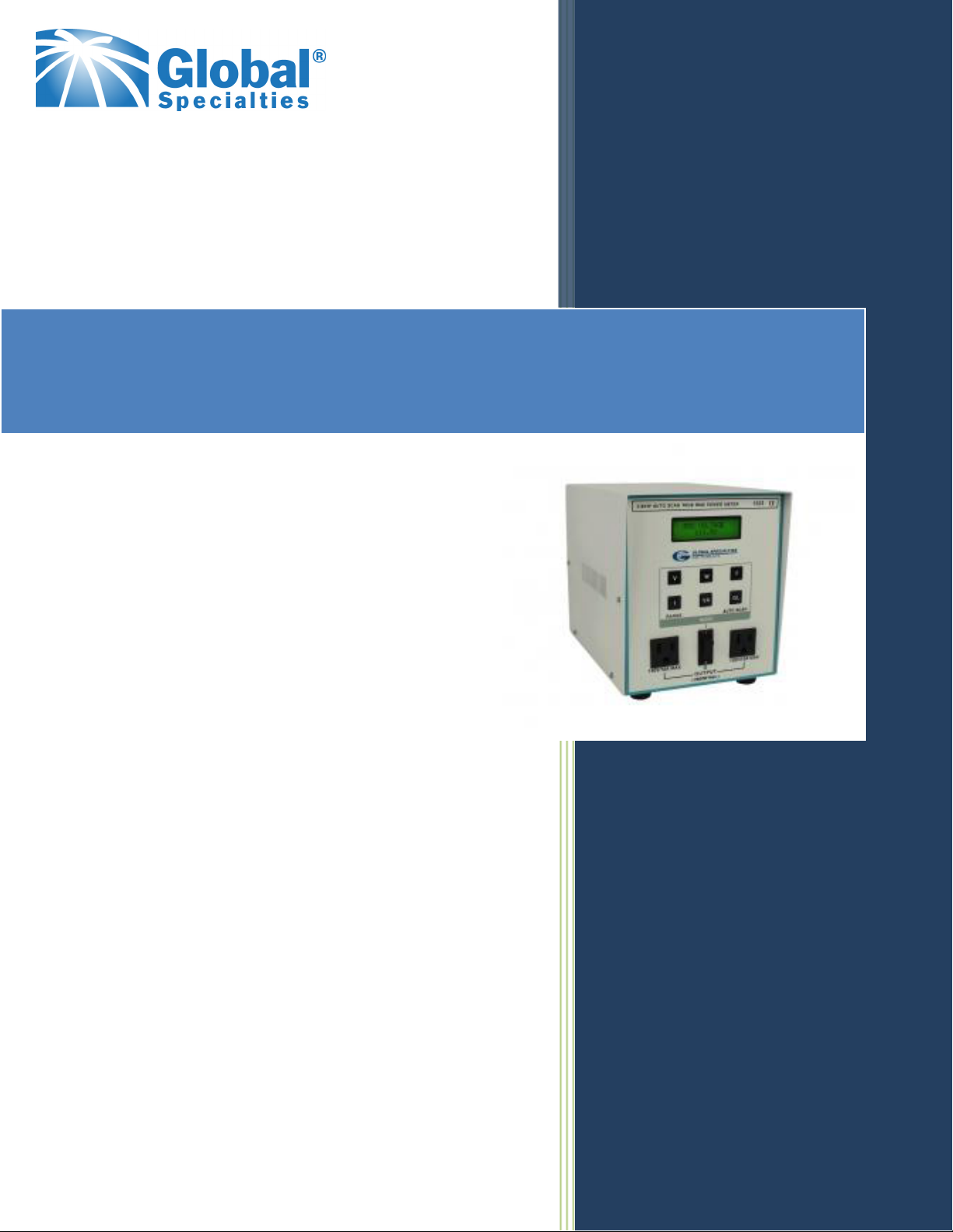
2.6KW Autoscan True RMS
Power Meter
INSTRUCTION MANUAL
TABEL OF CONTENTS
2 TECHNICAL SPECIFICATIONS 2
6 TESTING & CALIBRATION PROCEDURE 8
7 PART LIST 11
8 CIRCUIT DIAGRAMS & SCHEMATICS 16
.ON EGAP NOITPIRCSED NOITCES
1 SNOITCURTSNI YTEFAS 1
3 NOITPIRCSED LARENEG 3
4 NOITCURTSNI GNITAREPO 4
6 NOITACINUMMOC ETOMER 5
Page 3

SECTION - 1
SAFETY INSTRUCTIONS
The general safety information in this part of the summary is for both operating and servicing personnel.
Specific warnings and cautions will be found throughout the manual where they apply, but may not
appear in this summary.
1. This indicates refer to the manual wherever necessary.
2. E / Indicates Protective Ground Terminal.
3. Indicates Danger ! High Voltage.
4. Danger Arising fr om Loss of Ground
Upon loss of the protective-ground connection, all accessible conductive parts (including knobs and
controls that may appear to be insulating) can render an electric shock.
5. Use the Proper Fuse
To avoid fire hazard, use only the fuse of correct type, voltage rating and current rating as specific
in the parts list for your product. Refer fuse replacement to qualified service personnel.
6. Grounding the Product
This product is grounded through the grounding conductor of the power cord. To avoid electrical
shock, plug the power cord into a properly wired receptacle before connecting to the product input
or output terminals. A protective ground connection by way of the gr ounding conduct or in the
power cord is essential for safe operation.
Page 4

SECTION - 2
TECHNICAL SPECIFICATIONS
2.1 Measuring Parameters : True RMS V, A, VA, W and Frequency.
2.2 Measuring Limits
a) Voltage : 75V to 130V (115V operation).
b) Current : 0.2 to 20A rms AC (40A peak).
c) Volt Amperes : 16 to 2600VA.
d) Power : 1 to 2600W.
e) Power Factor : 0.5 to unity (No display).
f) Frequency : 45 to 65Hz.
2.3 Measurement Accuracy
a) Voltage / Current : 0.5% of reading ±1 digit.
b) Volt Amperes/Power: 1% of reading ±2 digits.
c) Power Factor : 2% of reading ±2 digits.
d) Frequency : 0.25% of reading ±1 digit.
Note : i) Accuracy valid only between above specified measurement limits.
ii) For VA, Power accuracies are valid only when voltage and current are between
2.4 Measurement Resolution
a) Voltage : 0.1V.
b) Current : 1mA upto 1 Amp., 10 mA above 1Amp.
c) Volt Amperes : 1VA.
d) Power : 1 Watt.
e) Frequency : 0.01Hz.
2.5 Miscellaneous
a) Display : 16x2 Alphanumeric LCD display.
e) Interface : RS232.
2.6 Power : 75V to 130V (115V operation).
2.7 Instrument Power : 9W approx.
Consumption
2.8 Operating Temperature : 5°C to 50°C, 90% RH.
2.9 Dimensions (mm) : 155 (W) x 190 (H) x 286 (D) approx.
2.10 Weight : 3 Kg. approx.
their respective limits.
Page 5

SECTION - 3
GENERAL DESCRIPTION
3.1 INTRODUCTION
Global Specialities' 2.6KW AUTOSCAN TRUE RMS POWER METER, MODEL 1523 is a state-of-
the-art instrument, ideal for providing all the information about any electrical load connected to the
AC Mains. It m onito rs/sca ns se que nt ially all electrical parameters viz., Voltage, Current, Power,
VA, & Mains Frequency, thus providing a clear picture of the load.
User operation is very simple. The load which is to be monitored is connected to the ‘Output’
Socket provided on the rear panel of the 1523 instrument. Each output is rated upto 130V & 10A
rms current. The instrument is then connected to the 115V AC mains. All the parameters are then
displayed on the LCD on front panel of the instrument.
An optional facility of remote communication has been provided. Through this, an external PC can
control the instrument and obtain information from it. This is possible b y making use of a set of
commands, details of which are explained later.
3.2 RECEIVING INSTRUCTIONS
The instrument is packed in a corrugated box. For unpacking, remove the box cover & packing
material. Then bring out the instrument from the box.
Check carefully, whether there is any physical damage to the instrument during transit. Inform the
carrier about the damage alongwith the serial number of the instrument (located on the bottom
cover).
3.3 POWER REQUIREMENTS
The wiring of the instrument is done as per the marking on the rear panel, viz ‘Mains In’ 105V -
130V AC, 50/60Hz.
3.4 INSTALLATION
The instrument is ready for operation when shipped from the factory. The appliance/load whose
power is to be monitored should be at a safe distance from the instrument. This prevents
unnecessary heating up of the instrument.
Page 6

SECTION - 4
OPERATING INSTRUCTION
4.1 IDENTIFICATION OF CONTROLS
1. V - This key is to display the measured mains rms volt age in V olts on LCD.
2. W - This key is to display the power consumed by load, every second, on LCD.
3. F - This key is to display the mains frequncy in Hz on LCD.
4. I / RANGE - This key is to display the rms value of measured load current in Amps on LCD.
5. VA - This key is to display the volt-amp of load on LCD and it is updated every second.
6. AUTO SCAN / GL - If instrum ent is not in remote m ode then this ke y acts as entry into auto scan
If any other key is pressed in auto scan mode,then unit comes out of auto scan mode and
If the unit is in remote mode of operation,this key acts as Go Local key.It brings the unit
7. DISPLAY- This is 16 x 2 Alphanumeric LCD display with green backlight.
mode. All parameters ie V,I,W,F,VA are scanned sequetially with a period of 1 second.
the selected parameter is displayed.
into local mode of operation.
Page 7

1. Mains In - Cord for delivering Mains Power(115V ac) to the instrument.
2. Output - Socket for plugging in the appliance / load to be monitored.There are 2 socets to share
the load of 20A equally.
3. Load Switch - Turns ON/OFF outgoing power to the loa d.Their are 2 switches for 2 output
sockets.
4. Fuse - Protective Fuse between mains & load.
5. RS232 Interface Connector - External PC communicates to the instrument using this
connector.
4.2 ELECTRICAL CONNECTIONS & MEASUREMENT
Follow the diagram & the instructions given below :
Fig. 3 Electrical connectons
a) Switch OFF the equipment under test.
b) Connect the Mains plug of the equipment/appliance, whose power is to be measured into
one of the Output sockets (2) of the 1523
c) With the corresponding load switch (3) of the 5051A in the ‘OFF’ position, Turn the mains
power on.
e) Switch ON the equipment/appliance & switch on the supply to the load with the
corresponding load switch(3).
Note : It is recommended that the 1523 be first switched ON and then the equipment under test.
4.3 METER OPERATION
The ‘LCD display’ (7) on front panel shows the measured parameter selected. On power
‘ON’, the Manual Scan mode is chosen. In this mode parameter selected with front panel key
displayed constantly on display.
1. Note : If the user connects some load to the instrument & switches it on with help of load
switch(3) and if the current displayed by the instrument is 0.000A then it indicates a blown
fuse. User should replace it with a new fuse.
Page 8

SECTION - 5
REMOTE COMMUNICATION
5.1 INTRODUCTION
By using the remote communication facility and the set of remote commands, a PC can
completely control the instrument and get information from it. During remote communication,
front panel is disabled (except Go Local key) as long as the remote PC doesn’t relinquish control
of the instrument or the GO Local key on front panel is pressed. Follow the diagram below for
connections.
Fig. 4 Serial communication Connections
a) Connect the com port of the PC to the female 9 pin D-type ‘RS232’ interface connector (5)
on the rear panel of the instrument.
b) Run any communication software like hyper terminal on the PC to communicate to the
instrument.Communication protocols are described as under.
5.2 COMMANDS FOR COMMUNICATION
Note : 1.Set Baud Rate = 9600 bits per second for serial communication.
Command Set:-
1. RV - Set ‘V’ function & Read input voltage in volts.
e.g. XXX.X ‘V’
2. RI - Set ‘I’ function & Read load current in amperes.
e.g. X.XXX ‘A’ or XX. XX ‘A’
3. RP - Set ‘P’ function & Read apparent power in Volt-Amperes.
e.g. XXXX ‘VA’
4. RW - Set ‘W’ function & Read Actual power in Watts.
e.g. XXXX ‘W’
5. RF - Set ‘F’ function & Read mains frequency in Hz.
e.g. XX.XX ‘Hz’
6. GL - To come out of Remote operation (i.e. Local Mode). Th is c ommand is acknowledged by
an answerback character. i.e. ’Y’.
7. SA - To enter into auto scan mode of all parameters. This command is acknowledged by an
answerback character. i.e. ’Y’.
8. Z - To flush buffer.
Note : To come out of Remote mode, GL switch on front panel can also be used.
Page 9

5.3 NOTES REGARDING COMMUNICATION
i) Definition of signals on ‘RS232’ interface connect or on rear panel (5) for remote
communication.
Pin No. Signal Source Description
2 RXD Remote PC Receive data from Remote PC
3 TXD Instrument Transmit data to Remote PC
5 Gnd — Signal Gnd
ii) Communication parameters
Bits per second - 9600
Data bits - 8
Parity - None
Stop bits - 1
Flow Control - None
iii) The commands to the instrument should be in upper case letters only.
iv) The instrument will not recognise if any wrong command is sent. Use flush buffer command
before proceeding.
Page 10

SECTION - 6
TESTING & CALIBRATION PROCEDURE
6.1 TITLE : Tes ting & C alibrat ion Proce dure of Power Meter 15 23
6.2 REF. DOCUMENTS : 5050Power Meter Test Procedure.
6.3 EQIPMENTS : 1) Power Meter
2) Voltmeter for AC Voltage & Current Meter up to 20A true RMS type.
3) Variac sourcing current up to 20A.
4) Frequency Counter.
5) Load up to 20A AC.
6.4 PROCEDURE :
6.4.1 Testing of PCBs :
1. Check all the PCBs for dry solder, loose contact of components capacitor polarities & ratings
2. Check for proper contacts of smd resistor networks of 10Kohms, on Main Board.
3. Connect all the Boards as per wiring diagrams.
6.4.2 Testing of Power Supply :
1. Switch on the Mains supply ( 115V ) to the unit.
2. Check the various supply voltages on CPU Board such as +5V, -5V at test points TP3 &
6.4.3 P ower on Display :
Switch on mains. On power on welcome message appears which is as follows :
APLAB MODEL : 1523
TRUE RMS MAINS : POWER METER
VERSION : V 1.00
Now the system carries out eprom-test & initializes the system variables if necessary. On
EPROM TEST : OK
Else the following message is displayed :
EPROM TEST : FAIL
V : ININ W : IGNOR
If V key is pressed it initializes the eprom. If the system is unable to initialize the eprom, it
EPROM ERROR : Else if W key is pressed it ignores EPROM fail. Now Mains voltage screen is
6.4.4 Testing Microcontroller 859S52 :
1. Check for momentary high ( +5V ) pulse at pin 9 (RESET) of 89S52 on power on or pressing
2. Check pin 30 (ALE) of U1 (89S52) to be a pulse signal of 2MHz with counter.
3. Check frequency at TP1 wrt GND to be 2MHz with counter.
4. Keep all other presets & trimmers in middle position. Adjust preset VR1 on CPU board for
etc.
TP4 wrt GND & reference voltage with U1-12 should be 2.500V wrt GND.
Successful EPROM test is shown.
displays following message on 2nd line of display:
displayed on LCD.
reset switch SW1 on CPU board.
proper contrast of LCD.
Page 11

6.4.5 Testing of Manual & Auto Mode :
1. All the parameters can be viewed with the keys on front panel i.e. V, I, W, VA, F.
2. Compare V & I values on display with standard DMM. Also calculate & compareVA & Power
for ( for resistive load power should be equal to VA ).
3. Auto scanning of all parameters can be done by pressing Auto scan / GL key. Auto scanning
is do ne a t speed of 1 Sec. To come out of auto scan mode, press any other key.
6.4.6 Mains Voltage Calibration :
Set mains input voltage to the unit is at 115.0 Volts at 50/60Hz frequency and monitor voltages at
DMM & Power meter simultaneously. Adjust the display to be the same with help of preset VR1
on main board. Check voltages for the range specified ( 75V - 130V ).
6.4.7 Mains Current Calibration :
1. Connect 500mA of load to the system & adjust 0.500A on power meter display with the help
of preset VR2.
Now to calibrate the current throughout the range up to 20A, following procedure is to be
followed.
2. Connect 250mA load physically & switch off the load switch on the meter.
3. To enter software calibration mode, reset the system & press Fk ey. After successful eprom
test, systems shows following screen.
CALIBRATION ?
YES = PRESS W KEY
NO = PRES VA KEY
4. If VA key is pressed then the system exists calibra tion m od e & m ains voltage in m anual mode
is displa yed.
5. To go into calibration mode, connect port pin 1.5 ( pin 5 of U2-89S52 ) to ground & press W
key.
6. Go to current mode by pressing I switch. ‘CAL’ message will be displayed along with normal
manual current mode screen.
7. W & VA keys will now function to increase & decrease the display counts respectively.
8. Use standard DMM to get same current on standard meter and on power meter.
9. Press F & AUTO SCAN/GL keys simultaneously to save the calibrated current value & Exit
Software Calibration Mode. The message ‘CALIBRATION SAVED’ will be flashed to confirm
saving.
10. Follow steps from 2 to 9 to calibrate the system on loads of 750mA, 5A & 15A & then verify all
readings.
11. Software Calibration mode will exit automatically without saving changes after 25 sec of idle
operation, it will show following message on display :
CALIBRATION
TIMEOUT
Page 12

SECTION - 7
PART LIST
PCB Components 5051A-MAIN-0306 IRD 551
=======================================================================
Ref Designator Value
========================================================================
RESISTORS
R1 470E SMD 0805 CHIP
R2 470E SMD 0805 CHIP
R3 16E CHIP 1/8W 1206
R4 1K 1% 0805 0.125W SMD
R5 10E SMD 0805 CHIP
R6 10K SMD 0805 CHIP
R7 12K SMD 0805 CHIP
R8 470E SMD 0805 CHIP
R9 470E SMD 0805 CHIP
R10 1K 1% 0805 0.125W SMD
R11 1K 1% 0805 0.125W SMD
R12 10K SMD 0805 CHIP
R14 10K SMD 0805 CHIP
R15 330E SMD 0805 CHIP
R16 1K 1% 0805 0.125W SMD
R17 620E SMD 0805 CHIP
R18* 10K SMD 0805 CHIP
R19 10K SMD 0805 CHIP
R20 100K 1% 0805 0.125W SMD
R21 2K4 SMD 0805 CHIP
R22 10K SMD 0805 CHIP
R23 2K7 1% 0805 0.125W SMD
R28 220E SMD 0805 CHIP
R29 20K SMD 0805 CHIP
R30* 1K8 0805 0.125W SMD
R31 220E SMD 0805 CHIP
R32 10E SMD 0805 CHIP
R33* 10K CHIP 1/8W 0805
NETWORK
RN1 TO RN9 10KE X4 x 1 COM 5 SMD
PRESETS
VR1 TRIMPOT 200E 10 TURN BOURNS
VR2 TRIMPOT 200E 10 TURN BOURNS
VR3 10K TRIMPOT HORZ
CAPACITORS
C1 10pF / 50V SMD CHIP 10% 0805
C2 10pF / 50V SMD CHIP 10% 0805
C3 10µF / 16V 2010MIL SMD ELE RAD
C4 100nF / 50V 10% 0805SM
C5 10µF / 16V 2010MIL SMD ELE RAD
C6 100nF / 50V 10% 0805SM
C7 100nF / 50V 10% 0805SM
C8 100nF / 50V 10% 0805SM
C9 220pF / 35V SMD CHIP 0805
C10 220pF / 35V SMD CHIP 0805
C12 18nF SMD 0805
C13 220pF / 35V SMD CHIP 0805
C14 220pF / 35V SMD CHIP 0805
Page 13

PCB Components 5051A-MAIN-0306 IRD 551
=======================================================================
Ref Designator Value
========================================================================
CAPACITORS
C16 18nF SMD 0805
C17 100nF / 50V 10% 0805SM
C18 10µF / 16V 2010MIL SMD ELE RAD
C19 33pF SMD CHIP 0805
C20 33pF SMD CHIP 0805
C21 100nF / 50V 10% 0805SM
C22 100nF / 50V 10% 0805SM
C27 3300µF / 35V 20% ELE RAD
C28 330µF / 25V ELE RAD
C29 10µF / 16V 2010MIL SMD ELE RAD
C30 100nF / 50V 10% 0805SM
C31 10µF / 16V 2010MIL SMD ELE RAD
C32 100nF / 50V 10% 0805SM
C33 10µF / 16V 2010MIL SMD ELE RAD
C34 100nF / 50V 10% 0805SM
C35 10µF / 16V 2010MIL SMD ELE RAD
C36 100nF / 50V 10% 0805SM
C37 1µF SMD CHIP 0805
C38 100nF / 50V 10% 0805SM
C39 100nF / 50V 10% 0805SM
C40 100nF / 50V 10% 0805SM
C41 100nF / 50V 10% 0805SM
C42 100nF / 50V 10% 0805SM
C43 ELE RAD 10µF, 16V
C44 100nf 50V CFI CHIP
CRYSTAL
X1 12MHz
X2 4.194304MHz
DIODE
D1 TO D4 1N4003 SMD MELF1
D5 RLS4148 T E11 SMD
ICs
U1 CS5460A 1PH POWER ENERGY 24 PIN TYPE SSOP
U2 89S52 UC 40 PIN 8 BIT FLASH 8KB ( DIP40 )
U3 74HC4053 16 PIN 2 CHANNEL ANALOG TYPE SO-16
U4 MNC 93C46N PI27 ATMEL MAKE ONLY
U5 LMV331 SMD 5 PIN LOW VOLTAGE COMPARATOR SOT23-5
U7 TL431-CP ADJ PRECISION REG SHUNT ( SOT23M1 )
U8 74HC14 SMD ( SO-14 ) HEX INVERTING SCHMIT TRIGGER
U9 IC UA7805UC REG / LM7805CT +5V
U10 UA7905UC REG -5V FIX
U11, U12 OP07 8 PIN SMD OP AMP ( SO8 ) ULTRA LOW-OFFSET
CONNECTORS
J1 4 PIN 2.54mm MALE
J2 DUAL IN ROW UNLOC MALE STRAIGH BURGE STRIP, 16 PIN
J3 3 PIN 2.54mm MALE
J4 4 PIN 2.54mm MALE
J5 DUAL IN ROW UNLOC MALE STRAIGTH BURGE STRIP, 10 PIN
JP1, JP3, JP5 3 PIN JUMPER MALE BREG STRIP BLK
JP7 2 PIN 2.54mm JUMPER LINK SIL MJ-02
SWITCH
SW1 TACT SWITCH TINY
Page 14

PCB Components 5051A-RS232-0706 IRD 570
=======================================================================
Ref Designator Value
========================================================================
RESISTORS
R1 1K SMD CHIP 1% 0.125W 0805
R2 10K SMD CHIP 0805
R3 200E SMD CHIP 0805
R4 2.4K SMD CHIP 0805
R5 1K SMD CHIP 1% 0.125W 0805
R6 10K SMD CHIP 0805
R7 200E SMD CHIP 0805
R8 2.4K SMD CHIP 0805
R9 220E SMD CHIP 0805
CAPACITORS
C1 10µF / 16V 20% ELE RAD
C2 10µF / 16V 20% ELE RAD
C3 10µF / 16V 20% ELE RAD
C4 10µF / 16V 20% ELE RAD
C5 470µF / 35V 20% ELE RAD
C6 10µF / 16V 20% ELE RAD
C7 100nF / 50V 10% 0805SM
C8 100nF / 50V 10% 0805SM
ICs
U1 TTL TO RS232 CONVERTOR 16 PIN
SMD SO-16
U2 OPTO ISOLATOR ISP817 4 PIN DIP
U3 OPTO ISOLATOR ISP817 4 PIN DIP
U4 UA7805UC REG/LM7805CT +5V
DIODES
D1 TO D4 IN4003 SMD MELF1
TRANSISTORS
Q1, Q2 MMBT3906 PNP SWITCHING SMD
SOT23
CONNECTORS
J1 3.96mm 3 PIN MALE ST MOLEX
J3 DUAL IN ROW UNLOC MALE
STRAIGHT BURGE STRIP, 10 PIN
J4 4 PIN ST MALE CONN JALEX
PCB Components ZG3M2020MTSO
=======================================================================
Ref Designator Value
========================================================================
CAPACITOR
C301, C302 CAP MP 1KV 47nF AXIAL
CORE
L301 FERRET RING CORE 10 x 6 x 3
Page 15

PCB Components 5051A-KBD-0306
=======================================================================
Ref Designator Value
========================================================================
SWITCH
S1 TO S6 ITTD 6 KEY BOAR
DBLACK HEIGHT 6mm
CONNECTORS
J1 DUAL IN ROW UNLOC MALE
STRAIGHT BURGE STRIP, 16 PIN
PCB Components LCD ASSY-16X2 HY-1602F-205 YELLOW
=======================================================================
Ref Designator Value
========================================================================
CONNECTORS
J1 16 PIN ST BREG STRIP BLACK
MECHANICALS
=======================================================================
Ref Designator
========================================================================
20A MAINS CORD
FUSE 20A
FUSE HOLDER 20A
115V SOCKETS AMERICAN 16A x 2
ON / OFF SWITCH 16A x 2
GLOBAL SPECIALTIES
INSTRUMENTS
1486 highland ave,cheshire,CT. 06410
800-572-1028 www.globalspecialties.com
M-00374 EDITION : 1 ( APRIL, 2007 )
Page 16

SERVICE AND WARRANTY INFORMATION
For up-to-date product information, please visit www.globalspecialties.com.
For instructions on how to obtain a return merchandise authorization number (RMA),
please visit our website, or call our customer service department.
GLOBAL SPECIALTIES
22820 Savi Ranch Parkway
Yorba Linda, CA 92887
800-572-1028
globalspecialties.com
Global Specialties will service and repair this instrument free of charge for a period of 3
full years, subject to the warranty conditions below.
WARRANTY
Global Specialties warrants the PB-503 to be free from defective material or
workmanship for a period of 3 full years from date of original purchase. Under this
warranty, Global Specialties is limited to repairing the defective device when returned to
the factory, shipping charges prepaid, within 3 full years from date of original purchase.
Units returned to Global Specialties that have been subject to abuse, misuse, damage
or accident, or have been connected, installed or adjusted contrary to the instructions
furnished by Global Specialties, or that have been repaired by unauthorized persons will
not be covered by this warranty.
Global Specialties reserves the right to discontinue models, change specifications, price
or design of this device at any time without notice and without incurring any obligation
whatsoever.
The purchaser agrees to assume all liabilities for any damages and/or bodily injury
which may result from the use or misuse of this device by the purchaser, his employees,
or agents.
This warranty is in lieu of all other representations or warranties expressed or implied
and no agent or representative of Global Specialties is authorized to assume any other
obligation in connection with the sale and purchase of this device.
All rights reserved. No Part of this book shall be reproduced, stored in a retrieval
system, or transmitted by any means, electronic, mechanical, photocopying recording,
or otherwise, without written permission from the publisher. No patent liability is
assumed with respect to the use of the information contained herein. While every
precaution has been taken in the preparation of this book, the publisher assumes no
responsibility for errors or omissions. Neither is any liability assumed for damages
resulting from the use of the information contained herein.
 Loading...