

Page 1
1335
&
1337
E
C Povver
Supply
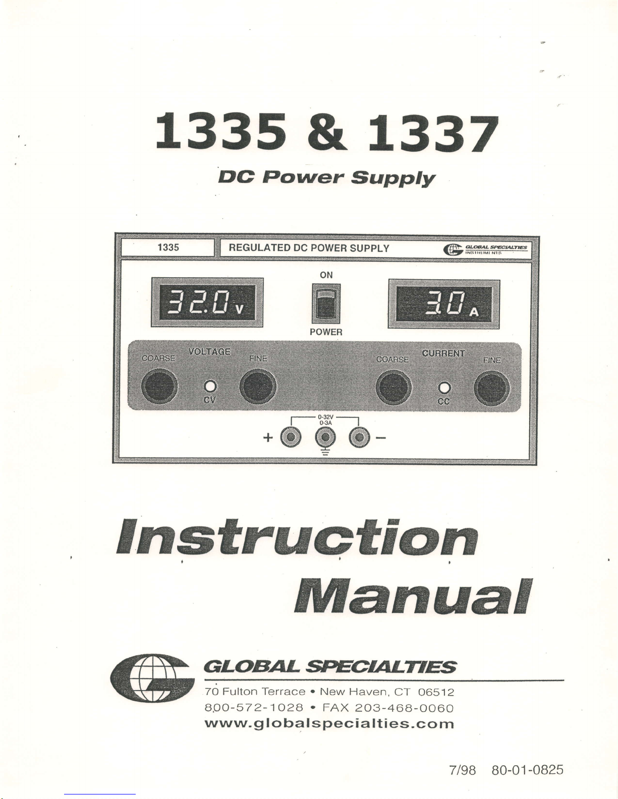
1335
REGULATED
DC POWER
SUPPLY
ON
m
EW
w
ffi
M
POWER
f-';:#-t
@@@
alF'
ww+tw
lElt;i{-srriffi-
Instruction
ManuaI
GLOBAL
70
Fulton Terrace . New
Haven,
CT
06512
B.OO-572-1O28
.
FAX
203-468-0060
www. g I obal
s
peci
a lties.
co m
7l9B
B0-01
-0825
Page 2

7335
E
C
Povver
Supply
Instruction
70 Fulton
Terrace
.
New
Haven
CT
065i2
aOO-
57 2- 1O2A
.
FAX
2O3-46a-
0060
www-g
loba
I spec
ia
lties
-cotr.l
ManuaI
GLOBALWre
7tqg
B0-01-0825
Page 3
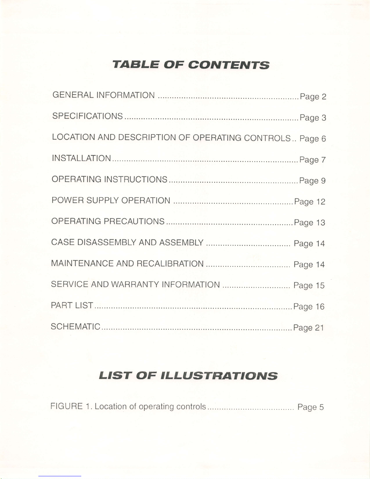
TABLE
OF
G,o.NTEATTS
GENERAL
INFORMATION
...
page
2
SPECIFICATIONS..
......
page
3
LOCATION
AND DESCRIPTION
oF OPERATING
CONTROLS..
page
6
INSTALLATION
....
page
7
OPERATING
INSTRUCTIONS
......
page
9
POWER
SUPPLY
OPERATION .
..page
12
OPERATING
PRECAUTIONS
..
....
page
13
CASE
DISASSEMBLY
AND
ASSEMBLY
...
.
page
14
MAINTENANCE
AND RECALIBRATION
....
page
14
SERVICE AND
WARRANTY INFORMATION
.....
page
15
PART
LIST
,... Page
10
SCHEMATIC
. Page
21
L'sT
OF
ILLUSTF|ATTOruS
FIGURE
1. Location
of operating
controls
..... Page
5
Page 4

GEI'EF|AL
TNFORMATION
DEscRIPTIo.N
The
1335
Power
Supply
is
a high
performance
singte
output
DC
power
supply
for
industrial
and laboratory
use.
Performance
with
economy
have
successfully
been
combined
to
provide
a compact,
fully
solid
state
instrument.
The
output
is
continuously
variable
from
o to
32v
and
can
supply
3A
max,
and
can
be adjusted
continuously
throughout
the
output
range.
The
front
panel
CURRENT
control
can
be
used
to
establish
the
outfut
current
limit (overload
or
short
circuit).
When
the
supply
is
used
as
a
constant
voltage
source
the
VOLTAGE
controls
can
be
used
to
limit
the
output
voltage.
When
the
unit is
used
as
a constant
current
source,
CURRENT
controls
can
be used
to limit
the
output
current.The
unit will
automatically
cross
over from
constant
voltage
to
current
mode
and
vice-versa,
if
the
output
current
or voltage
exceeds
these
preset
limits.
Output
voltage
and
current
are
continuously
monitored
on
two
front
panel
meters.
The
load
terminals
are
provided
on the
front
panel.
Either
the
positive
or
negative
output
terminal
may
be
grounded
or the
power
supply
can
be
operated
floating
at up to
a maximum
of t3ooVDC
above
ground.
All
the
outputs
are floating
i.e.
neither
the
output
positive
terminal
nor
the
negative
terminal
(nor
any
point
within
the regulator
circuitry)
is
con-
nected
to
ground.
The
power
supply
is
designed
to
operate
in
ambient
temperature
of
up
to
40"C
and
full
output may
be drawn
continuously provided
free
air
circulation
is
allowed.
The
unit works
from
mains
supply
of 11SVAC,
47-63
Hz.
2
GLOBAL*ECALTTT
INSTRUMENTS
Page 5
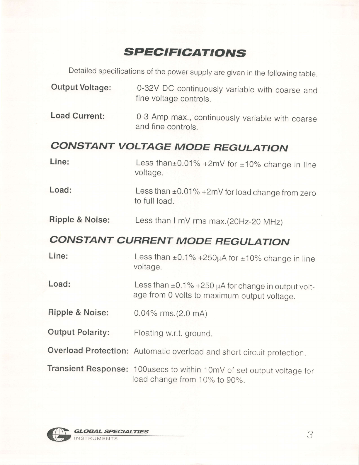
SPEc.IFTc.AT'OruS
Detailed
specifications
of
the
power
supply
are
given
in
the
following
table.
Output
Voltage:
0-32V
DC
continuously
variable
with
coarse
and
fine
voltage
controls.
Load
Current:
0-3 Amp
max.,
continuously
variable
with
coarse
and fine
controls.
cOA'STANT
VOLTAGE
MODE
REGULATION
Line:
Less
than*0.01"/"
+2mv
for
*
10%
change
in
rine
voltage.
Load:
Less
than
t0.01
"/o
+ZmV
for
load
change
from
zero
to full
load.
Ripple
&
Noise:
Less
than
I
mV
rms
max
.(2oHz-20
MHz)
cONSTANT
CURRENT
MODE
REGIJLATION
Line:
Less
than
t0.1"/o
+250pA
for
*
ro%
change
in
rine
voltage.
Load:
Less
than t0.1"/"
+250
pA
for
change
in
output
volt-
age from
0 volts
to
maximum
output
voltage.
Ripple
& Noise:
0.04%
rms.(2.0
mA)
Output
Polarity:
Floating
w.r.t.
ground.
Overload
Protection:
Automatic
overload
and
short
circuit
protection.
Transient
Response:
1OOprsecs
to within
l
OmV
of
set
output
voltage
for
load
change
from
10%
to
9O%.
GLOBAL*ECALTTre
.)
U
INSTRUMENTS
Page 6
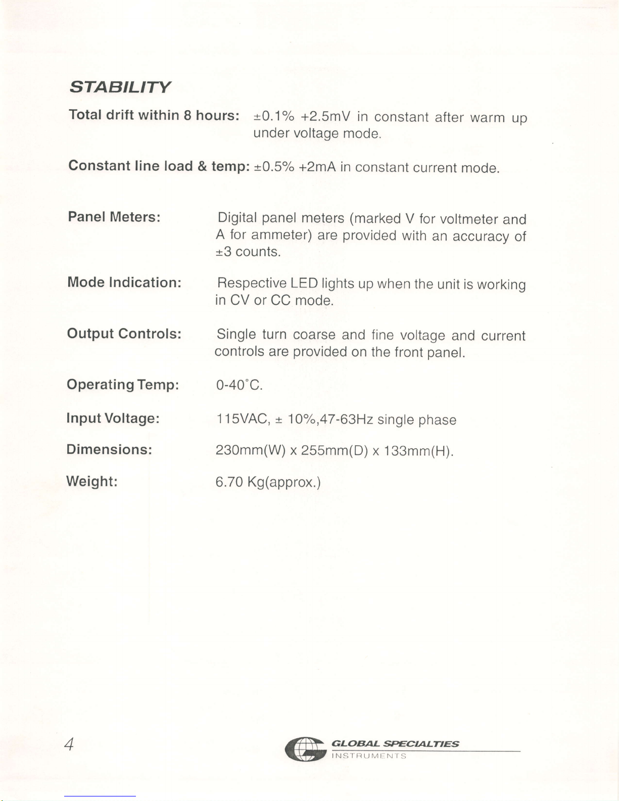
STABILITY
Total
drift
within
I
hours: t0.1"/"
+2.SmV
in
constant
after warm
up
under
voltage
mode.
Constant line
load
& temp:
t0.5"/"
+2mA
in
constant
current
mode.
Panel
Meters:
Digital
panel
meters
(marked
V for
voltmeter
and
A for
ammeter)
are
provided
with
an
accuracy
of
*3
counts.
Mode Indication:
Respective
LED lights
up when
the
unit is working
in
CV or
CC mode.
Output
Controls:
Single turn
coarse
and fine
voltage
and
current
controls
are
provided
on the
front
panel.
Operating Temp:
0-40'C.
f nput
Voltage:
1 1SVAC,
*
10"h,47-63H2
single
phase
Dimensions:
230mm(W)
x 255mm(D)
x 133mm(H).
Weight:
6.70
Kg(approx.)
GLOBAL
*ECALTIES
4
INSTRUMI:N'TS
Page 7
o)g
o
.b
q
o
o
(op
.=
*.
t!
\
o
Fo.
Fo
q\
o
c
oo
{:
(!
0
roo
_l
F.
€o
L
f,
o
ri
qGLOE'AL
*ECALT'ES
INSTRUMENI'S
Page 8
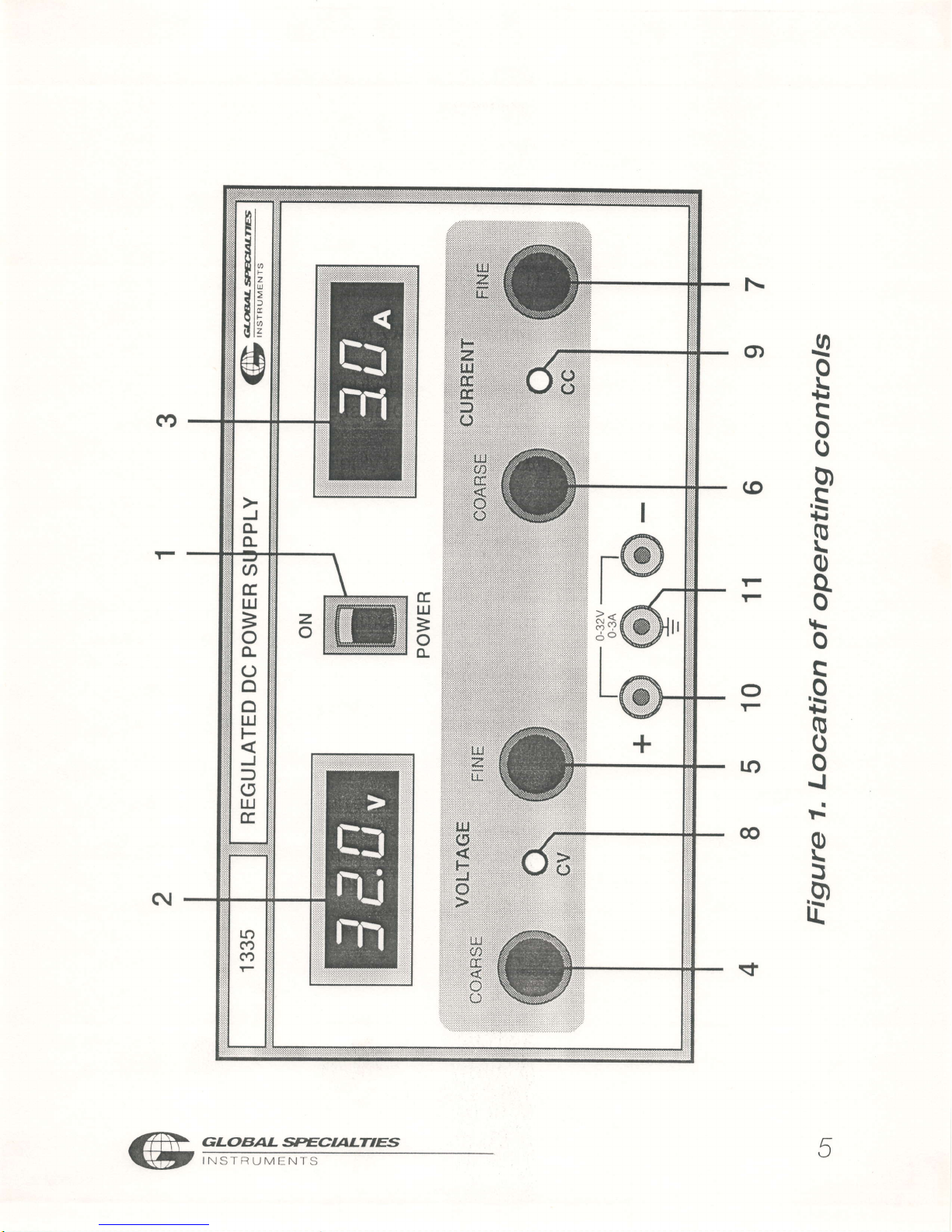
LOCATION
ANE'
DESG|FITPTIo|N
OF
oPEFATING
c'o.NTFro|Ls,
ln
order
to
use
the
full
capabilities
of the
1335,
it is
highly
recommended
that
the
user
become
familiar
with
the
controls
associated
with
this
in-
strument. (See
Figure
1)
1-
Power
oN/oFF
switch.
7-
current
Fine
control
clock-
wise
rotation
increases
vari_
2-
supply
LED
Display.
Dispray
able
output
current
in
cc
Voltage
0 to
32VDCmode
mode.
3-
Supply
LED
Display.
Disptays
current
0 to
3AMP.
B-
CV
LED
Constant
Voltage
In-
dication
4-
Variable
coarse
voltage
con-
g-
cc
LED
constant
cu rrent
trol.
clockwise
rotation
in-
Mode
Indication
creases
variable
output volt-
age
in
CV
mode.
10-
Output
terminals
Red
terminal
ts
output
(+)ve.
Black
termi_
5- Variable
fine
voltage
control.
nal
is
output
(-)ve.
Clockwise
rotation
increases
variable
output
voltage
in
cV
1 1-
Ground
terminal.
mode.
6-
Current
coarse
Control.
Clock-
wise
rotation
increases
vari-
able
output
current
in
cc
mode.
GLOBAL
*ECALTTES
6
INS'fRTJMI]NIS
Page 9

II'STALLATIOru
INITIAL
'NSPECTION
As
soon
as
the
power
supply unit is
unpacked
inspect
for
any
damage
that
may have
occurred
during
transit.
Save
all
packing
material
until
inspection
is
completed. lf
any damage
is found,
notify
the
carriers
im-
mediately.
Our authorized representatives
should
also
be notified.
PHYSICAL
CHECK
This
check
should
confirm that there
are no
broken
knobs
or
connec-
tors,
that the
cabinet
and
panel
surfaces
are free
of
dents
and scratches
and the meters
are
not
scratched
and
cracked.
ELECTRICAL
CHECK
The
power
supply unit should
be checked
against
electrical
specifica-
tions. An
in-cabinet
performance
check will verify
proper
operation.
'NSTALLATION
DATA
The
power
supply unit
is
shipped ready
for
bench
operation.
lt is neces-
sary only to
connect the unit to a rated
source
of
power
and it
is
ready
for
operation.
LOCATION
The
power
supply
unit
is naturally
cooled.
Sufficient
space should
be
kept
around the unit while in
operation, so that heat
sinks do not remain
in
confined
space
or
close
to
another heating
source. The
ambient
temperature
of
the
area
around the
unit
should
be
less
than 40"C.
INPUT
POWER REQUIREMENTS
The
power
supply unit may be operated
continuously
from input voltage
of 1 15 volts
47 Io
63Hz
power
source.
GLOBAL*ECALT'6
7
INSTRUMENTS
Page 10

X
To
ensure
safe
shipment
of the
power
supply
unit,
it
is
recommended
that
the
package
designed
for
the
unit
be
used.
The
original
packaging
material
is reusable.
Be
sure
to
attach
a
tag
to
the
unit
specitying
the
owner,
and
the
fault
observed
with
a
brief
description.
See
page
15
for
service
information.
REMOVING
COVER
The
top
cover
is retained
in
place
by
6 self
tapping
screws
&
two
handle
mounting
screws.
To
remove
cover,
proceed
as
follows:
a) Remove
the
chrome-plated
handle
caps.
b)
Remove
the
handle
mounting
screws.
c) Remove
the
self tapping
screws
on
sides.
d) Lift
the
cover from
rear
side,
slide
backwards
&
pull.
GLOBAL
*ECIALT'ES
INSI-f]TJMEN'TS
Page 11

O
P E
RATI
N
G-'AISTF
U
CTTO^'S
TURN
ON
SE77'NG
PROCEDURE
The
following
procedure
describes
the
use
of
controls
and indicators.
a.
Ensure
that
the
AC
power
switch
is in
the
"oFF"
position.
b.
Connect
the
unit to
a specified
input
voltage.
c. Turn
the VOLTAGE
and
CURRENT
controls
fully
counter-clockwise.
d.
Set'POWER
ON'Switch
to
"ON" position.
The
front
panel
digital
meters
will light
up and voltmeter
and
ammeter
displays
will
read
zero,
and
observe
that
CV LED
glows.
e. Adjust
the"VOLTAGE"
controls
till
the
desired voltage
is
indicated
on
voltmeter
f. To
check
"CONSTANT
OURRENT"
mode,
turn
oFF
the
supply.
short
circuit the
output terminals
of the
power
supply
and turn
ON the
supply.
g.
Adjust'CURRENT'controls
until the
desired
output
current is indi-
cated
on
ammeter. Also
check
that
the
CC LED
glows.
h. Remove
the
short
circuit.
cONSTANT
VOLTAGE
MODE
To
select
a constant voltage
output,
proceed
as follows:
Connect
a digital voltmeter
(DVM)
across
the
output
terminals,
ob-
serving
correct
polarity.The
DVM
must
be rated
for
better
than
0.s%
accuracy.
Turn
the
CURRENT
controls
clockwise.
And
slowly
turn the voLT-
AGE
controls
clockwise
and observe
both the
front
panel
voltmeter
and the DVM.
Compare
the
DVM
reading
with
the
front
panel
volt-
meter reading
to
verify
the
accuracy
of
the
internal
voltmeter.
a.
b.
GLOBAL*ECAL:I1E
Y
INSTRUMENTS
Page 12

c.
The VOLTAGE
control range
will
be from
minimum
to
the
maximum
rated
output
voltage.
Adjust
desired
voltage
by
adjusting
the voltage
controls.
d.
Short
circuit
output terminals
and
adjust
CURRENT
controls
for
maximum
output
current
as required
by the
load
conditions.
lf
a load
change
causes
the
current
limit
to
be
exceeded,
the
power
supply
will
automatically
cross
over
to
constant
current
output
at current
limit
and
output voltage
will
drop
proportionately.
In
setting
the
cur-
rent
limit,
allowance
must
be made
for
high
peak
currents
which
can
cause
unwanted
crossover.
cONSTANT
CURRENT
MODE
To
select
a constant
current output,
proceed
as follows
Short
circuit
the
output terminals
of the
power
supply.
connect
a
DC
Ammeter
oR
a shunt-digital
voltmeter
(DVM)
combi-
nation
across
the
output terminals,
using
appropriately gauged
wire
and hardware.
The
recommended
current
ratings
for
the
ammeter
or
the
shunt
and the wire
must
be at least
10%
more
than
the
output
current
of the
power
supply modelThe
ammeter
or
shunt-DVM
com-
bination
must
be
rated
better than
0.5%
accuracy.
Turn
the
VoLTAGE
controls
clockwise.
And
turn
the
CURRENT
con-
trols
slowly
clockwise.
The
CURRENT
control
range
will
be f rom
mini-
mum
to
maximum
rated
outputburrent.
Adjust
CURRENT
controls
for
desired
output
current.
Compare
the
ammeter reading
with
the front
paner
ammeter
reao-
ing.
or, compare
the DVM
reading
with
the
front
panel
ammeter
read-
ing
using
| = V/R,
where V ls
the DVM
reading
and R is
the
DC
shunt
resistance.
open
output
terminus
and
adjust VoLTAGE
controls
for
maximum
output
as
required
by the load
conditions.
a.
b.
c.
d.
e.
10
^aR
GLoBAL*EaALTnT
Gttffi
Page 13

lf a load
change
causes the
voltage
limit
to
be exceeded,
the
power
supply
will
automatically
cross
over
to
constant
voltage
output
at the
preset
voltage
limit
and output
current
will
drop
proportionately.
In
set-
ting
voltage
limit,
allowance must
be made
for
high
peak
voltages
which
can cause
unwanted
crossover.
LOAD
CONNEG-TIONS:
The load
should
be connected
to
the
power
supply
output
terminals
using
separate
pairs
of connecting
wires.
This
will
minimize
mutual
cou-
pling
effects
between
loads
and will
retain
full
advantage
of the
low
output impedance
of the
power
supply. Each
pair
of
conhecting
wires
should
be as
short as
possible
and twisted
or
shielded
to reduce
noise
pick
up.
(lf
a shielded
pair
is
used,
connect
one
end
of the
shield to
ground
at
power
supply and leave
the
other
end
unconnected).
Positive
or
negative
voltage
can
be obtained
from
this
supply
by
ground-
ing
either
one of the
output terminals
or one
end
of the load.
Always
use
two leads
to
connect load to
the
supply, regardless
of where
the
set
up
is
grounded.
This will
eliminate
any
possibility
of the
output
current
re-
turn
paths
through
the
power
source
ground
which
would
damage
the
line
cord
plug.
This
supply can
also
be operated
up to
t30OV
DC
above
ground,
if neither
output terminal
is
grounded.
GLOBAL *ECALT'ES
71
INSTRIJMENTS
Page 14
POWER
SUPPLY
o.PEFtATIo|/^'
INITIAL
s,ET
UP
Refer
to the
preceding
section
for
initial
set
up
of the
power
supply.
O P E
RATI
N
G'NSTR
U CT I
ONS
Proper
operation
of most
circuitry
depends
on
correct
supply
voltages.
It
is recommended
that
the
power
supply
be
set to
the
required
voltage
levels
with the
load
disconnected.
When
the
desired
voltage
is
set
(us-
ing
the variable
voltage
control),turn
the
AC
power
OFF
and
connect
the
load
to the
power
supply. Turn
the
AC
power
oN.
output voltage
and
current
of the
power
supply
may
be read
on the
separate
digital
panel
meters
continuously.
GLOBAL
*ECALT'6
12
INS I
lltJMl:N
fS
Page 15

O P ERATI
N
G
P
R
ECAI'TT
o..^'S
The
power
supply
is ideally
suited
for virtually
any
type
of lC
bread
boarding
f rom
TTL,
CMOS
and ECL
to
op-amps,
audio
and
video
amps,
phase
locked
loops,
and microprocessor
circuitry.
However,
certain
nor-
mal
breadboarding
precautions
should
be taken
to
avoid
ground
loops
and
inadvertent
loading.
Observance
of
correct
load polarity
is
also
important
since
most lcs
may
be damaged
by improper power
supply
connections.
POLARITY
observe
proper
polarity
when
connecting
the
power
supplies
to
the
load,
especially
if
the load is
polarity
sensitive
and
does
not
nave
re-
verse
polarity
protection.
GROUND
LOOPS
A
ground
loop is
a voltage
drop
on
a
ground
bus
caused
by
a
power
stage
output
entering
the
ground
bus
some
distance
away
from
the
power
supply
ground
binding
post.
This
small voltage
drop, though
only
milliVolts
or microVolts,
is
a
part
of
the
output
load.
lf
a
preamplifier
input
of circuit
ground
is
connected
to
a
portion
of this
ground
bus, feedback
and
oscillation
may
occur.
To
prevent
this
all output
stages
should
be
positioned
as close
as
possible
to
the
ground
terminal,
preamps
farther
away.
Many
audio lC's
have
separate
input
and
output
grounds
to
prevent
ground
loops.
Even
though
power
supplies
are tightly
regulated,
a
short length
of a
power
bus can
present
enough inductance
to
cause
linear
lC
oscillation
at
high
frequencies.
For
this reason,
effective
bypass
capacitors
are
needed
to
bypass the
power
buses. Place
these
capacitors
as
close as
possible
to the
power
supply
pins
of the
lC.
Ceramic
disc
(0.1
pF
)
work
well
and
should
be
placed
across
as
many
lCs
as
possible.
Do
not
use
electrolytic
or
paper
capacitors
because
they
have
high inductances
and
cease to
act
as bypasses
above
one
or two MHz.
Bypassing
is
required
with
digital lC's
also;
problems
such
as inability
to reset
or to
clear and false
triggering
can occur if
lc's
are not
properly
bypassed.
/A
cLoBAL*EcaLTrE
Gtt
' ," - -..,
"r'
*, '
-
13
Page 16

c.As.E
DTsi,Asi.s,EMBLY
ANE'
ASSE/[/'BLY
WARN'NG
Potentially
lethal
AC
power
is
present
whenever
the
line
cord is
plugged
into
the
AC
outlet,
even
when
the
power
switch
is
oFF.
Always
disconnect
the
power
cord when
opening
the
case. Avoid
touching
the
fuse
post
on the in-
side
of the
unit.
Should
access to the
inside
of the
unit
be required, proceed
as follows:
1. Remove
the
line
cord
from
the
AC
outlet
before
disassembly
2.To
disassemble
the
case, remove
the
screws
that
secure
the
cover to
the
chassis
and lift the
cover off.
3. To reassemble
the
case,
place
the
cover
on the
chassis,
line
up the
screw holes,
and replace
the
screws.
MA] fdTENAn,c.E
AN
E'
RECALI
f'.FrATIo.^'
ADJUSTMENTS
All
circuitry is factory-calibrated.
No
user adjustments
are
required.
FUSE
REPLACEMENT.
Remove
the line
cord from the AC
outlet
before
changing
fuses.
Using
a
screwdriver, remove
the fuse holder
cap. Replace
the fuse
with
an-
other of identical
type
and current rating.
Replace
the fuse
holder
cap.
GLOBAL
*ECALT'ES
14
INSI'R(JMI]N'I'S
Page 17

SEHWCE
AAI
E'
WARRAATTY
I
N FIOFI'/II',ITTo/N
FACTORY
S.ERVIC.E
AND
REPAIR
Global
Specialties
will
service
and repair
this
instrument
f ree
of
charge
for
a
period
of one full
year
subject
to the
warranty
conditions
stated
below.
To
obtain
a return
merchandise
authorization
(RMA)
required
for
all
re-
turns,
phone
our
customer
service
department
for
a RMA
and
all
shipping
instructions:
Tel:
BO0-572-1028
or write
GLOBAL
SPECIALTIES
70 Fulton
Terrace.
Box
1942
New
Haven,
Connecticut
00509
ATTN
:
Customer
Service
Department
WARRANTY
Global
Specialties warrants
this
device
to
be free
from
defective
material
or workmanship
for
a
period
of
3
years
from
the
date of
original
purchase.
Global
Specialties
under this
warranty
is limited
to
repairing
the
defective
device
when returned
to the factory,
shipping
charges
prepaid,
within
three
full
years
from
the
date
of original
purchase.
Units
returned
to
Global
Specialties
that
have
been
subject
to
abuse,
mis-
use,
damage
or accident
or have
been connected,
installed
or
adjusted
con-
trary to
the instructions
furnished
by
Global
Specialties,
or that have
been
repaired
by
unauthorized
persons
will not
be
covered
by this
warranty.
Global
Specialties
reserves
the right
to
discontinue
models,
change
speci-
fications,
price
or design
of this
device
at
any time
without
incurring
any
obli-
gation
whatsoever.
The
purchaser
agrees
to
assume
all liabilities
for
any
damages
and/or
bodily injury
which may
result from
the
use
or misuse
of this
device
by the
purchaser
his
employees or
agents.
This warranty
is in
lieu
of all other representations
or warranties
expressed
implied
and no
agent
or
representative
of Global
Specialties
is authorized
to
assume
any
other obligation in
connection
with
the
sale
and
purchase
of this
device.
J^.
GLaBALffiEaaLTTE
V
r\rr*rrJr/rr
N 15
4r
tc
Page 18

PART
LIST
PCB
Components
ZSDT.CT/o1
PCB
REV
.
01
Ref
Designator
Value
RESISTORS
R1
R2
R3
R4*
R5
R6
R7
RB
R9
R10
R11
R12
R13
R14
R15
R16
R17
R18
R19
R20
R21
R22
R23
R24
R25
R2B
R27
R28
R29
R30
R31
R32
R33
R34
R35
t-tJo
R37
R3B
270E,2W,5%,MOR
47E,MFR,114W,5"/"
1
0K,MFR,1l4W.
1 K,MFR,
1
l4W,soh
(OPTO)
1
0E,MFR,1/4W5%(SCR)
3.9K,MFR,1l4W
3.3K,2W,5%,MOR.
10K,MFR,1l4W.
8.2KMFR,1l4W.
100K,MFR,1l4W
4.7OHM,MFR,1/4W.
1.5K,MFR,1l4W.
1 BOK,MFR
,114W,
390E,MFR,1l4W.
6.BK,MFR
,114W,5"/"
12K,MFR,114W,5"/"
3.9K,MFR, 114W,5"/o
1
0K. M FR, 1
l4W.
10K,MFR,1l4W.
1OK,MFR,1I4W,
3.3K,2W,5%,MOR
270E,2W,5%,MOR,
g2K,MFR,1l4W,50/"
4.7K,MFR
,114W,5"/"
24E,MFR,114W,5"/"
820E,MFR
,114W,5"/"
330K,MFR
,114W,50/o
3gK,MFR,1l4W5%
1BOK,MFR
,114W,5"/"
1K,MFR,1l4W,5"/o
15E,MFR,1/4W,5"/"
6.gK,MFR
,114W,5"/o
15K,MFR,1l4W5%
6.8K,MFR
,114W,5"/"
15K,MFR,1l4W,5"k
1K,MFR,1l4W,5%
2K,MFR,1l4W,5"/"
1 K,MFR,1l4W,50/"
GLOBAL *ECAL:T1ES
to
INS'TRUMEN'TS
Page 19

PCB
Components
ZSDT-CT/o1
PCB
REV
-
01
Ref Designator
Value
R39
R40
R41
R42
R43.
R44
R45
R46*
R47"
R48
R49
R50
R51
PRESETS
PR
101
PR 102
PR
103
CAPACITORS
c1
C2
C3
c4
c5
C6
C7
C8
C9
c10
c11
c12
c13
c14
c15
c16
c17
c18
c19
c20
c21
1K,MFR,1l4W5%
4.7K,MFR
,114W,5"/o
330K,MFR
,
114W,5/"
1
00E, M FR,1
I 4W,5"/"(l
CAL)
4.7K,
M FR,1
I
4W,5"/"(l
CAL,SEL)
1 K,MFR,1l4W,5"/"
1K,MFR,1l4W,5%
5.
1 K,MFR,1
14W,5"/"(V
CAL,SEL)
1
00E, M FR,1 I 4W,So/o(V
CAL)
2K,MFR,1l4W,5"/"
3.6K,MFR
,114W,5"/"
Shorting
Link
10E,MFR,114W,5"/"
5K, PRE,Lt N(VXDEV.
DROP)
500E,
PRE,LtN,(V)(V
CAL)
500EPRE,UN,(V)
(t
CAL)
0.1pF/100VMP
0.1pF/250VAC
MKP
15,000ptF/50V
ELE,
LUG
TYPE
0.lpF/S0VMP 10%
33pFR/50VELE
100uF/50VELE
100pF/50VELE,
l
piF/SOV,ELE
4.7prFl50V,ELE
2.2uFlSOVELE.
100pF/50VELE.
47pFl50V,ELE.
l KPF/sOV.CD.
l KPF/sOV,CD
0.1pF/50V,CD.
10pF/50V,ELE.
10pF/50VELE.
0.1rtF/SOVCD.
22OptFlS0V,ELE
220pFl50V,ELE
47urFl50VELE
GLOBAL*ECAL'AE
I NSTRUM ENTS
77
Page 20

PCB
Components
ZSDT.CT/01
PCB
REV
.
01
Ref
Designator
Value
c22
c23
c24
c25
c28
DIODES
cR1
cR2
cR3
cR4
cR5
CR6
CR7
cR8
cR9
cR1 0
cR1
1
cR1
2
cR1
3
cR1
4
CR1 5
CRIB
CR1
7
cR1 8
CR1
9
cR20
cR21
CR22
cR23
CR24
cR25
cR26
CR27
cR28
CR29
ZEN ERS
21
22
z3
10pF/50VELE
0.1pF/50VCD.
10pF/50V,ELE.
10pF/50VELE.
0.1pF/50VCD.
Not
Used
1N4007,1KV/1A
1N4007,1KV/1A
1N4007,1KV/1A.
1N4007,1KV/1A
1N4007,1KV/1A
1N4007,1KV11A
1N4007,1KV/1A.
1N4007,1KV/1A.
1N4007,1KV/1A
1N4007,1KV/1A
1N4007,1KV/1A.
1N4007,1KV/1A.
1N4007,1KV/1A
1N4007,1KV/1A.
1N4007,1KV/1A.
1N4007,1KV/1A.
1N4007,1KV/1A.
1N4007,1KV/1A.
1N4007,1KV/1A.
1N4007,1KV/1A.
1N4007,1KV/1A.
1N4007.1KV/1A.
1N4007,1KV/1A.
1 N4148,1
00V/1OmA
1N4148,100V/1OmA
'1
N4148,1
00V/1OmA
1
N41 48,100V/1
OmA
1N4007,1KV/1A.
1N758,10V/0.4W
1N758,10V/0.4W
1N750,4.7Vl0.4W
GLOBAL*ECALTTE
7B
I NSTRUM
EN.rS
Page 21

PCB
Components
ZSDT.CT/o1
PCB
REV
.
01
Ref Designator
Value
BRIDGE
BR1
BR2
lc's
tc1
tc2
tc3
lc4
tc5
tc6
lc7
tcB
Transistor's/FET/SCR
Q1
Q2
Q3
Q4
Q5
FETl
SCRl
CONNECTORS
coNl
CON2
CON3
CON4
MISCELLANEOUS
TP1
TP2
TP3
TP4
TP5
TP6
1
OA/I6OOVDC,PC
MTG
BRIDGE
CSB-1,1
OOV/1 APC
MTG
BRIDGE.
4N250PTO
7812
(+12Vl1A
FIXED)
T1431(2.5V
SHUNT
REG)
LM324
7812(+1211A
FIXED)
T1431(2.5V
SHUNT
REG)
79105
(-sV/1
00mA FIXED).
7805
(+5V/1A).
BC10e
(TO-18)
MPSAT2
(TO-e2)
8C557
(ro-e2)
8C557
(TO-e2)
8C547
(TO-e2)
IRFP46O
SCR 2N6396
3.96mmPlTCH,
3PlN M
2.S4mmPlTCH,
12PlN
M
2.54mmPlTCH,
12PlN
M, LTYPE
2.S4mmPlTCH,
6PlN M, L
TYPE
RIM PIN MALE
RIM PIN MALE
RIM PIN MALE
RIM PIN MALE
RIM PIN
MALE
RIM PIN MALE
GLOBAL*ECALNE
INSTRTJMENTS
19
Page 22

PCB
Components
2XZ-DPM/01
PCB
REV-01
Ref
Designator
Value
RESISTORS
R1
R2
R3
R4*
R5
R6
R7
R8
R9
PRESETS
PR1
CAPACITORS
c1
c2
c3
c4
C5
c6
c7
c8
c9
c10
lC's
lc1
VR1
FND's
DS1
D52
DS3
MISCELLANEOUS
J1
J2
J3
39K,0.25,5%,MFR
470K,0.25W,5%,MFR
1M,0.25W,57o,MFR
sEL(rNPUr)
10K,0.25W,5%,MFR
2K4,0.25W,57o,MFR
330E,0.25W57o,MFR
330E,0.25W,57o,MFR
6K8, 0.25W,57o,MFR
2.5K,LtN,VER (REF
ADJ)
220pF,50V
CD
0.1pF,100VMP
0.01pf,SOVCo
0.47,p"F,100VMP
0.1pF,100VMP
0.1pF,100VMP
1OpF,50VEL
0.1pF,50VCD
10uF,50VEL
0.1pF,50VCO
7107
DECODER
DRIVER
TL-431
TSD566
GREEN
TSD566
GREEN
TSD566
GREEN
2.54PITCH,
3PIN M
NOT
USED.
2.54PITCH,4PIN
M
20
,+
cLoBAL
sEcr/rLTrEs
Etffi
Page 23

PCB
Components
Z-TR|O1
PCB
REV-01
Ref
Designator
Value
RESISTORS
R1
R2
R129*
CAPACITORS
c1
c2
c3
DIODE
cR1
1K,zW5"/",MOR
0.1 8,2.5W,57o,WW
33K,0.25W5%,MFR
0.1pF,50VCD
100pF,50VEL
10pF,50VEL
1 N5402X2
GLOBALgECAL'Tre
I NSTRU M
ENTS
21
Page 24

JJ
ld ul
ul ul
tl
(r
l0N
f,0.G
ooo
OH
Jroo
OZZJJ
+ts{F{<I>
o
@Ft
tm
oa
>22>
ou9t0
I co+
J
nuJ
c,n
J
d
or
(J
of
{{
(J
o
o?
(x
N
H
:)
()
e.
H
o
(r
(L
r/l
H
o
O
lrJ
c_ro
tn+
lrO()
o oo-
lt
tl19N-l
or!
GNo
+ur+
t!oO
o
o{L
old
cmo
+n+
trou
('0.
f
o
o
-{
J
o
0_oJ
(wt
<roq
<tfO tl!.'
oro
Lm
(.'ot
qW'
ol.)
HZb
lrjGl
C0f(rh tlN
<r\.t.l <t(Y
j-tZJO
(IlN
xZiEH
9(\1
ocl
(-rl
uH
O+
(J-{
dlrlJO
L.'l
(ru[fF.r
C-i
>lrll4-
(Il-{
ooQf,0
9-{
OVPOr O-{
OUI().{
.e;
I
c;
Page 25

s
c
c
I
o
q
$r
3
tE
L
:o
:0
i<
i9
:\
iT
iN
o
a?
!!o
cr
P6
az
E
!
F
J
i.i
8
;
I
t1
li:
lu
t
I
<o
l"N
co
n
L
t
N.
UO
io
sR
q
o
IT
II
Page 26

 Loading...