

Page 1

Test Equipment Depot - 800.517.8431 - 99 Washington Street Melrose, MA 02176
TestEquipmentDepot.com
1320
Triple Output High Resolution
Power Supply
User Manual
Page 2

Safety Summary
The following safety precautions apply to both operating and
maintenance personnel and must be observed during all phases
of operation, service, and repair of this instrument. Before
applying power, follow the installation instructions and become
familiar with the operating instructions for this instrument.
GROUND THE INSTRUMENT
To minimize shock hazard, the instrument chassis and cabinet
must be connected to an electrical ground. This instrument is
grounded through the ground conductor of the supplied, threeconductor ac power cable. The power cable must be plugged into
an approved three-conductor electrical outlet. Do not alter the
ground connection. Without the protective ground connection, all
accessible conductive parts (including control knobs) can render
an electric shock. The power jack and mating plug of the power
cable meet IEC safety standards.
DO NOT OPERATE IN AN EXPLOSIVE ATMOSPHERE
Do not operate the instrument in the presence of ammable
gases or fumes. Operation of any electrical instrument in such an
environment constitutes a denite safety hazard.
KEEP AWAY FROM LIVE CIRCUITS
Instrument covers must not be removed by operating personnel.
Component replacement and internal adjustments must be made
by qualied service personnel. Disconnect the power cord before
removing the instrument covers and replacing components.
Under certain conditions, even with the power cable removed,
dangerous voltages may exist. To avoid injuries, always
disconnect power and discharge circuits before touching them.
Test Equipment Depot - 800.517.8431 - 99 Washington Street Melrose, MA 02176
TestEquipmentDepot.com
1
Page 3

DO NOT SERVICE OR ADJUST ALONE
Do not attempt any internal service or adjustment unless another
person, capable of rendering rst aid and resuscitation, is
present.
DO NOT SUBSTITUTE PARTS OR MODIFY THE INSTRUMENT
Do not install substitute parts or perform any unauthorized
modications to this instrument. Return the instrument to Global
Specialties for service and repair to ensure that safety features
are maintained.
WARNINGS AND CAUTIONS
A WARNING statement calls attention to an operating procedure,
practice, or condition, which, if not followed correctly, could result
in injury or death to personnel.
A CAUTION statement calls attention to an operating procedure,
practice, or condition, which, if not followed correctly, could result
in damage to or destruction of parts or the entire product.
WARNING: Do not alter the ground connection. Without the
protective ground connection, all accessible conductive parts
(including control knobs) can render an electric shock. The
power jack and mating plug of the power cable meet IEC safety
standards.
WARNING: To avoid electrical shock hazard, disconnect
power cord before removing covers. Refer servicing to qualied
personnel.
CAUTION: Before connecting the line cord to the AC mains,
check the rear panel AC line voltage indicator. Applying a line
voltage other than the indicated voltage can destroy the AC line
fuses. For continued re protection, replace fuses only with those
of the specied voltage and current ratings.
CAUTION: This product uses components which can be
damaged by electrostatic discharge (ESD). To avoid damage,
2
Page 4

be sure to follow proper procedures for handling, storing and
transporting parts and subassemblies which contain ESDsensitive components.
COMPLIANCE STATEMENTS
This product is subject to Directive 2002/96/EC of the European
Parliament and the Council of the European Union on waste
electrical and electronic equipment (WEEE), and in jurisdictions
adopting that Directive, is marked as being put
on the market after August 13, 2005, and should
not be disposed of as unsorted municipal waste.
Please utilize your local WEEE collection facilities
in the disposition of this product and otherwise
observe all applicable requirements.
Test Equipment Depot - 800.517.8431 - 99 Washington Street Melrose, MA 02176
TestEquipmentDepot.com
3
Page 5

Table of Contents Page
1 Introduction .............................................................5
1. Overview ...................................................................................5
2. Features ....................................................................................5
2 Installation ...............................................................5
1. Initial Inspection ........................................................................5
2. Input Power Requirements ..........................................................6
3. Ventilation .................................................................................6
3 Product Description ..................................................7
1. Front Panel ................................................................................7
2. Rear Panel .................................................................................9
4 Operating Instructions .............................................9
1. Setting the Output Voltage and Output Current ............................9
2. Constant Voltage (CV) /Constant Current (CC) Mode ...................10
3. System Conguration ................................................................11
5 Specications .........................................................15
6 Maintenance ...........................................................16
1. Preventative Steps ....................................................................16
2. When the Unit is Not Turning On ...............................................16
3.
Fuse Replacement ....................................................................16
7 Service and Warranty Information ........................17
1. One Year Warranty ...................................................................17
2. Calibration and Repair ..............................................................17
4
Page 6

Test Equipment Depot - 800.517.8431 - 99 Washin
TestEquipmentDepot.com
gton Street Melrose, MA 02176
1 Introduction
1. Overview
Global Specialties Model 1320 Triple Output High Resolution DC
Power Supply provides two variable outputs (0 – 30V / 0 – 3A)
and one
independently, in series tracking, or parallel mode. Conveniently
adjust voltage and current with independent front panel knobs
and bright quad display. This power supply is ideally suited for
applications in electronic test, production, and service, where
multiple independent DC power supplies are required and bench
space is at a premium.
2. Features
xed output (5V / 3A). The variable outputs can work
z Separate 4-digit displays for voltage and current on vari-
able outputs
z Three independent outputs
z Individual control of voltage and current for variable outputs
z CV (constant voltage) / CC (constant current) mode opera-
tion
z LED indication for CV / CC mode
z Overload indication LED for fixed output
z Series tracking and parallel mode operation
z Power On/Off switch on front panel
z Input voltage selection on rear side (120 VAC/ 240 VAC)
2 Installation
1. Initial Inspection
This unit is tested prior to shipment. It is therefore ready for
immediate use upon receipt. An initial physical inspection should
be made to ensure that no damage has been sustained during
shipment.
Inspect the packing box on receipt for any external damage.
If any external damage is evident, remove the instrument and
visually inspect its case and parts for any damage. If damage to
5
Page 7

the instrument is evident, a description of the damage should be
noted on the carrier’s receipt and signed by the driver or carrier
agent. Save all shipping packaging for inspection. Forward a
report of any damage to the agent through which the unit is
procured.
Retain the original packing in case subsequent repackaging for
return is required. Use of the original packing is essential.
After the mechanical inspection, verify the contents of the
shipment. The items included in this package are:
z 1320 Power Supply
z Power Cord
z User Manual
z Banana Plug to Alligator Clip Lead Wires (Black & Red)
2. Input Power Requirements
The instrument can operate on 120 V or 240 VAC source at 50
or 60 Hz. The line selector plug on the rear panel allows you to
select the line voltage. Before connecting the power plug to an
AC line outlet, be sure to check that voltage selector plug is set
in the correct position corresponding to the line voltage in your
location and the fuse rating is as shown in the table.
Selector Line Voltage Fuse
120 V 100~125 V, 50/60 Hz 6 A
240 V 220~240 V, 50/60 Hz 3 A
3. Ventilation
Before applying power to unit, make sure that input voltage
setting is correct and the ventilation holes are not blocked.
Ensure that the ventilation fan located on the rear panel is
working well (it should turn on when powered on). Do not load
the output if ventilation fan is not working otherwise it may cause
the power supply to overheat.
Test Equipment Depot - 800.517.8431 - 99 Washington Street Melrose, MA 02176
TestEquipmentDepot.com
6
Page 8
3 Product Description
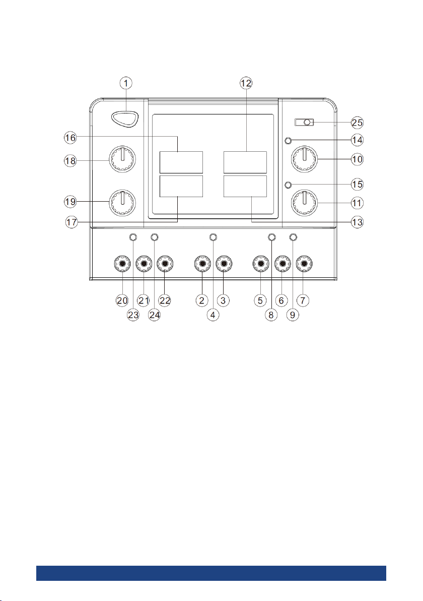
Figure 1. Front Panel
1. Front Panel
1. Power switch
2. Negative output terminal of the xed 5V/3A output
(black)
3. Positive output terminal of the xed 5V/3A output (red)
4. Overload indicator LED for the xed 5V/3A output
5. Negative output terminal of the MASTER output
6. Ground terminal of the master output
7. Positive output terminal of the master output
8. CC mode LED for the master to indicate constant current
9. CV mode LED for the master to indicate constant voltage
10. Master voltage adjustment knob
7
Page 9

11. Master current adjustment knob
Master voltage indicator display (4-digit green 0.36”
12.
LED)
13.
Master current indicator display (4-digit red 0.36” LED)
14. Series mode indicator LED
15. Parallel mode indicator LED
16. Slave voltage indicator display (4-digit green 0.36” LED)
17. Slave current indicator display (4-digits red 0.36” LED)
18. Voltage adjustment knob for adjusting slave output voltage when master power is in CV mode
19. Current adjustment knob for adjusting slave output current when master power is in CC mode
20. Negative output terminal of the slave output
21. Ground terminal of the slave output
22. Positive output terminal of the slave output
23. CC mode LED for the slave to indicate constant current
24.
CV mode LED for the slave to indicate constant voltage
25. Function mode switch: Select “IND,” “SER,” or “PAR”
position for “Independent,” “Serial Tracking,” or “Parallel
Mode,” respectively.
Figure 2. Front Panel Diagram
Test Equipment Depot - 800.517.8431 -
TestEquipmentDepot.com
99 Washington Street Melrose, MA 02176
8
Page 10

2. Rear Panel
A. Heat sink: Heat dissipation for power transistor
B. Ventilation Fan: 8” 24 VDC fan
C. Power input socket
D. Fuse holder and input voltage selector: The selected in-
put voltage is set to the voltage shown near the
which points to “E.”
E. The input power voltage indicator: The
mark points to
the set input line voltage
mark
Figure 3. Rear Panel
4 Operating Instructions
1. Setting the Output Voltage and Output Current
1. As per load requirement, calculate the voltage and max-
imum current limit to be set on output. Note: V=IR
2. Disconnect the load from output terminals.
3. For current limit adjustment, turn the current adjustment
knob counter-clockwise to get minimum current output.
4. Short the circuit between the positive and negative output terminals by the accessory leads.
5. Vary the current adjustment knob clockwise until the
current displays the required current limit. The CC LED
9
Page 11
will be lit while adjusting the current limit. Remove the
accessory lead after current limit adjustment.
6. The voltage will be displayed again and the CV LED will
be lit.
7. Vary the voltage adjustment knob to get the desired output voltage on the display.
Depending on load condition, the power supply will work either in
CV or in CC mode. The automatic changeover is indicated by the
CV / CC LEDs.
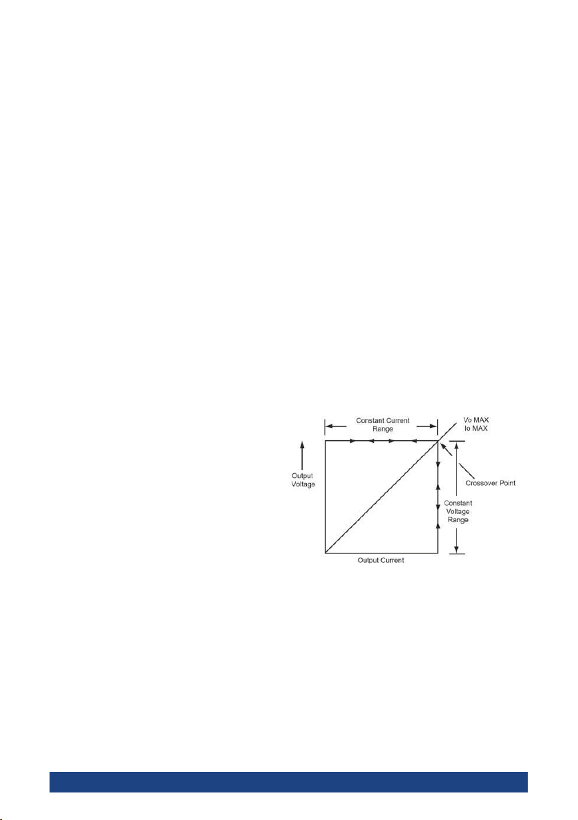
2. Constant Voltage (CV) /Constant Current (CC) Mode
The working characteristic of this power supply is called a
constant voltage/constant current automatic crossover type. This
permits continuous transition from constant current to constant
voltage modes in response to the load change. The intersection
of constant voltage and constant current modes is called the
crossover point. Figure 4 shows the relationship between this
crossover point and the load.
For example, if the load is
such that the power supply
is operating in the constant
voltage mode, a regulated
output voltage is provided.
The output voltage remains
constant as the load
increases, up until the point
Figure 4. CC/CV Characteristics
where the preset current limit
is reached. At that point, the output current becomes constant
and the output voltage drops in proportion to further increases
in load. The crossover point is indicated by the front panel LED
indicators. The crossover point is reached when the CV indicator
goes off and the CC indicator comes on. Similarly, crossover from
the constant current to the constant voltage mode automatically
occurs from a decrease in load.
Test Equipment Depot - 800.517.8431 - 99 Washington Street Melrose, MA 02176
TestEquipmentDepot.com
10
Page 12

3. System Conguration
Models 1320 has two variable outputs, which can work
independently, in series tracking mode, or parallel mode by
toggling the function mode switch. Users can also connect
multiple units in series or parallel mode to increase their voltage
or current.
Independent Mode
a.
Ensure the function mode switch is in the “IND” position. Connect
the appropriate load between the positive and negative terminal.
b. Series Tracking Mode
In this mode, the negative output terminal of the master gets
connected internally to the positive output terminal of the slave.
1. Toggle the function
mode switch to “SER”. The green
LED will light up to indicate series tracking mode.
2.
Set output voltage with
the voltage adjustment knob of
the master. The display of the
master shows half the voltage
of the actual output available
Figure 5. Series Tracking Mode
across the positive output termi
-
nal of the master and the nega-
tive output terminal of the slave.
3.
Connect the load across the positive output terminal
of the master and the negative output terminal of the
slave.
c. Parallel Tracking Mode
In this mode, the positive output terminal of the master gets
connected internally to the positive output terminal of the slave
and the negative output terminal of the master gets connected to
11
Page 13

the negative output terminal of the slave. The output voltage will
be the same as the master set value and the output current is
twice the set master output current.
1. Toggle the function
mode switch to “PAR”. The red
“Par” LED and the red “Par.CC”
LED of the slave output will light
up to indicate parallel tracking
mode.
2.
Turn both the slave voltage adjustment knob and current
adjustment knob clockwise to
maximum.
Figure 6. Parallel Tracking Mode
3. Set the output voltage
with master voltage adjustment knob. The output current will be twice that of the set master output current.
4. In parallel mode of operation, connect the appropriate
load between the positive and negative terminals of the
master (or between the positive and negative terminals
of the slave).
d. Multiple Units in Series Mode
For achieving higher voltage, two or more units can be connected
in series (CAUTION
: 240 V max). The output voltage of the
system will be the sum of all units. The output current will be the
same for all units.
1.
Switch all units to “SER” mode and adjust each to the
same output voltages.
2. Connect the negative of the slave output terminal of unit
1 to the positive of the master output terminal of unit 2.
3. Connect the load between the positive of the master
terminal of unit 1 and the negative of the slave terminal
of unit 2.
Test Equipment Depot - 800.517.8431 - 99 Washington Street Melrose, MA 02176
TestEquipmentDepot.com
12
Page 14

Figure 7. Multiple Units in Series
e. Multiple Units in Parallel Mode
Two or more units can be connected in parallel to obtain a higher
current output (CAUTION: 24 A max). The output current of the
system will be the sum of all units. The output voltage of the
system will be the same for all units.
Figure 8. Multiple Units in Parallel
13
Page 15

1. Switch all units to “PAR” mode.
CAUTION. Adjust all units to the same output voltages.
2.
3.
Make the parallel connection of the positive and the
negative terminals of the master and slave outputs for
all units.
4. Connect the load between the positive and negative of
the master on the last unit.
f. Fixed 5V/3A Output
This is the standard 5V/ 3A power output provided for supplying
the power to TTL logic circuits. When the load exceeds 3A, the
red OVERLOAD LED will light up.
The output voltage will be
lowered and the power supply will switch to CC mode.
Test Equipment Depot - 800.517.8431 - 99 Washington Street Melrose, MA 02176
TestEquipmentDepot.com
14
Page 16
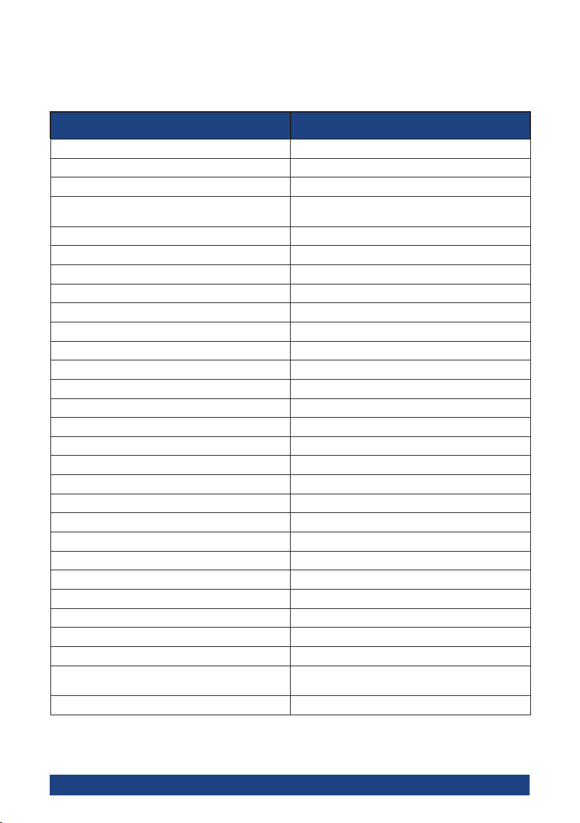
5 Specications
All specications apply to the unit after a temperature stabilization time of 15 minutes over an
ambient temperature range of 25 ºC ±5 ºC.
1320 Power Supply
Output Parameters
Max Output Power 207 W
Number of Outputs 3 independent & electrically isolated outputs
Range Variable: 0-30 VDC / 0-3 A (2)
Max Continual Output Power 195 VA
Load Regulation
CC Mode <0.2% + 3 mA
CV Mode <0.05% + 5 mV
Line Regulation
CC Mode <0.2% + 2 mA
CV Mode <0.05% + 3 mV
Ripple & Noise
CC Mode <2.5 mArms
CV Mode <0.4 mVrms
Fixed 5 V Output <1.5 mVrms
Tracking Operation
Slave Tracking Error <0.5% + 2 digits of the master
Display Accuracy
Voltage & Current <0.05% + 3 digits
Fixed 5 V Output ± 0.25 V
General
AC Input VAC 120/240 ±10%, 50/60Hz ±10%
Operating Temperature 50 ºF to 104 ºF (10 ºC to 40 ºC)
Operating Humidity 90% R.H.
Temperature Coefcient <300 PPM / ºC (voltage and current)
Dimensions (W x H x D) 9 x 7 x 12 in (230 x 170 x 310 mm)
Weight 17.6 lbs (8.0 kg)
Included Accessories Power cord, user manual, one pair of test
Warranty One Year Warranty
Fixed: 5 V / 3 A (1)
leads
Specications are subject to change without notice. To ensure the most current version of this
manual, please download the current version from our website: globalspecialties.com.
15
Page 17

6 Maintenance
1. Preventative Steps
Please follow these preventive steps to ensure the proper
operation of your instrument.
z Never place heavy objects on the instrument.
z Never place a hot soldering iron on or near the instrument.
z Never insert wires, pins, or other metal objects into ventila-
tion fan.
z Never move or pull the instrument with power cord or out-
put lead. More importantly
when the power cord or output lead is connected.
z Do not obstruct the ventilation holes in the rear panel as
this will increase the internal temperature.
z Do not operate the instrument with the cover removed un-
less you are a qualified service technician.
z Clean and recalibrate the instrument on a regular basis to
keep the instrument looking nice and working well.
z Remove any dirt, dust, and grime whenever they become
noticeable on the outside cover using a soft cloth moistened with a mild cleaning solution.
, never move the instrument
2. When the Unit is Not Turning On
Check if the power ON/OFF switch is turned ON. Check for
blown fuse. If not, then check the power cord. Please make sure
that the power cord is properly connected to the unit. Please also
check the main switch and ensure that the
is the same as the one mentioned at the rear chassis of the unit.
Fuse Replacement
3.
If the fuse blows, the LED will not light and the instrument will
not operate. Replace only with the correct value fuse. The fuse is
located on the rear panel adjacent to the power cord receptacle.
Remove the fuse holder assembly as follows:
AC supply at your site
16
Page 18

z Unplug the power cord from the rear of the instrument.
z Insert a small screwdriver in the fuse holder slot (located be-
tween fuse holder and receptacle).
z When reinstalling fuse holder, be sure that the fuse is installed
so that the correct line voltage is selected.
7 Service and Warranty Information
1. One Year Warranty
Cal Test Electronics warrants this product to be free from
defective material or workmanship for a period of 1 year from
the date of original purchase. Under this warranty, Cal Test
Electronics is limited to repairing the defective device when
returned to the factory, shipping charges prepaid, within the
warranty period.
Units returned to Cal Test Electronics that have been subject to
abuse, misuse, damage or accident, or have been connected,
installed or adjusted contrary to the instructions furnished by Cal
Test Electronics, or that have been repaired by unauthorized
persons, will not be covered by this warranty.
Cal Test Electronics reserves the right to discontinue models,
change specications, price, or design of this device at any time
without notice and without incurring any obligation whatsoever.
The purchaser agrees to assume all liabilities for any damages
and/or bodily injury which may result from the use or misuse of
this device by the purchaser, his employees, or agents.
This warranty is in lieu of all other representations or warranties
expressed or implied and no agent or representative of Cal
Test Electronics is authorized to assume any other obligation in
connection with the sale and purchase of this device.
2. Calibration and Repair
If you have a need for any calibration or repair services, please
visit us on the web at: globalspecialties.com. See the “Service”
tab. Or contact us via the “Contact” tab.
Test Equipment Depot - 800.517.8431 -
TestEquipmentDepot.com
99 Washington Street Melrose, MA 02176
17
Page 19

Page 20

20150922
 Loading...