

Page 1
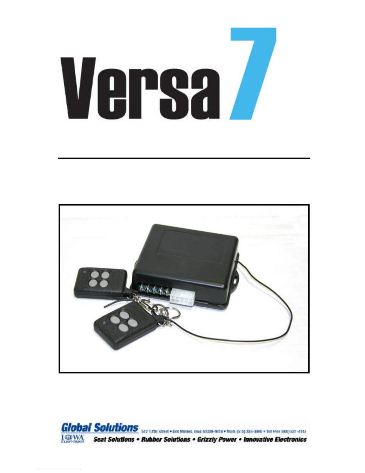
Seven Channel Remote Control
Page 2
The Versa7 is designed to remotely control up to seven
devices, or functions. All seven functions can be controlled with the supplied four button remote control.
Channels 1 and 2 are tied to onboard 30 AMP relays
and may be used to control two functions up to 30
AMPs directly. Channels 3—7 are electronic outputs
with a 500 milliamp current limitation. Typically these
outputs are connected to a relay/s for control functions.
These optional relays are not part of this kit.
Proper wiring is critical to the correct operation of this
product. Make sure that all wires are properly connected, properly grounded, and free of potential damage, and correctly fused. Please refer to the wiring diagrams in the following pages.
For technical assistance please call:
515-283-3900
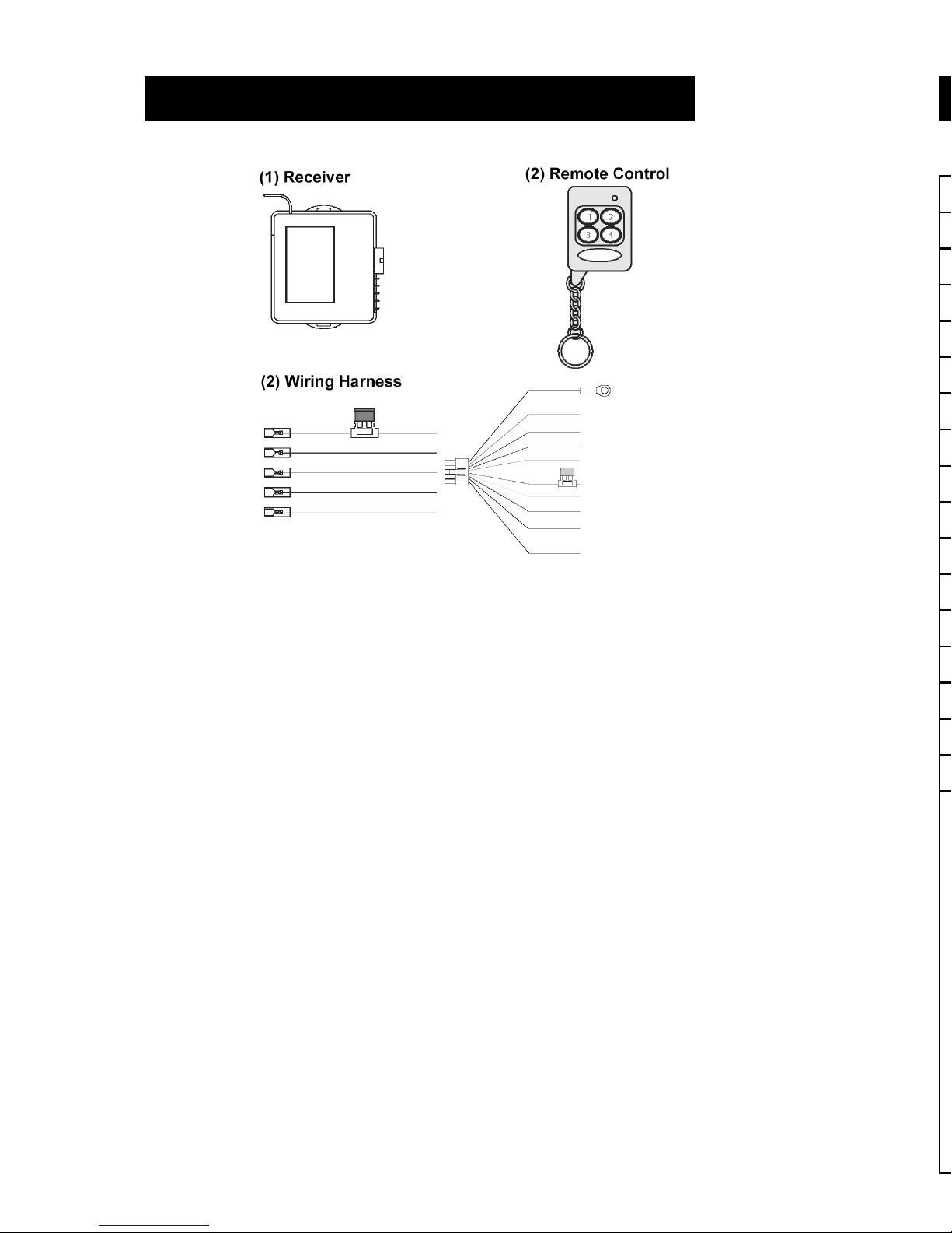
Versa7 Kit Contents
Page 1
Installation Notes
Page 10
Page 3
Basic Functions Of The Remote Control
Remote Control Operation
Channel 1: Onboard relay
Channel 2: Onboard relay
Channel 3:
Channel 4:
Channel 5:
Channel 6:
Channel 7:
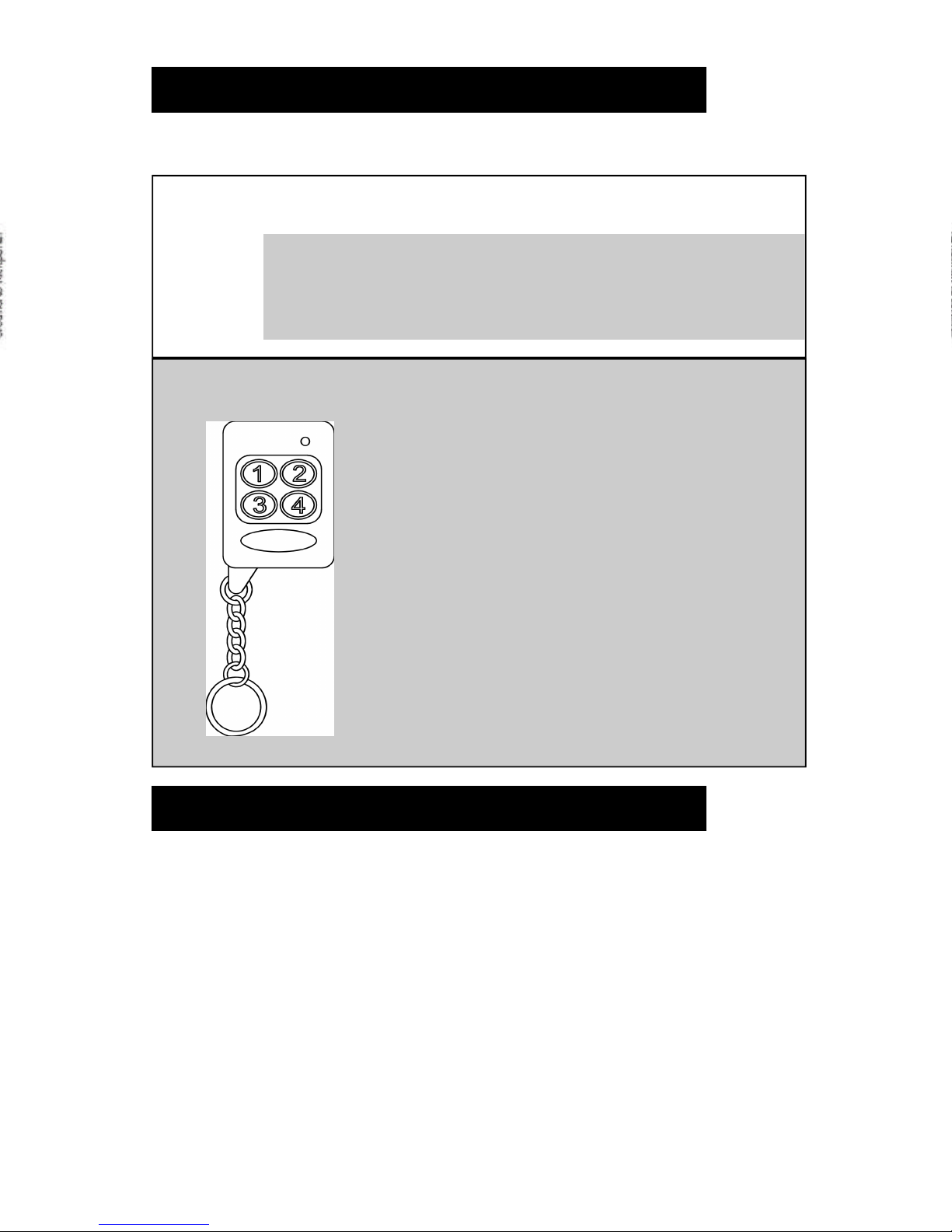
The remote control supplied with your kit has four buttons, but is capable of controlling 7 Channels.
Optional negative outputs (500 mA)
**Additional relays are required for each channel**
To Operate: Press:
Channel 1 Button 1
Channel 2 Button 2
Channel 3 Button 3
Channel 4 Button 4
Channel 5 Button 1 + Button 2
Channel 6 Button 1 + Button 3
Channel 7 Button 1 + Button 4
Remote Control Programming
Reprogramming the Remote Transmitters:
The remote transmitters are shipped Pre-Programmed. In the event that
a remote transmitter loses the programmed code, or if you wish to add
more remote transmitters, follow these steps:
• Make sure ignition is OFF.
• Locate the programming button located on the side of the receiver
next to the LED.
• Press the programming button 3 times quickly (the LED will light).
• Press Button (1) on each transmitter you want learned in to the re-
ceiver (one at a time). There is a 10 second window to learn all new
transmitters.
• The LED will remain lit for approximately 10 seconds after the last
been recognized.
• Wait for the LED to go out. Then test each transmitter for proper
function.
Page 2
Page 4
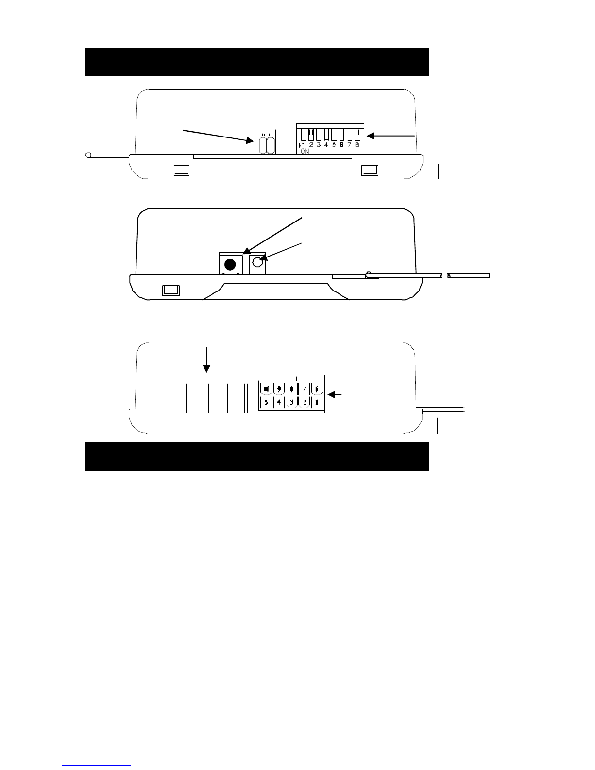
Components Identification
Remote Programming Button
LED Light
DIP Switches
Jumpers
DO NOT MOVE POSTION UNLESS
INSTRUCTED BY TECHNICAL
SUPPORT
10 Pin Connector
Main Harness Plug
1/4” Male Spade Connectors
CH1 & CH2 Outputs
Mounting Considerations
Choose your mounting location carefully. The Versa7 should be securely mounted in an area that will remain dry, and not be subject to
excessive shock and vibration. Additionally, try not to mount the Versa7 in a fully enclosed metal area, this will affect the operational
range of the unit.
THE VERSA7 RECEIVER AND REMOTE CONTROL UNITS ARE
NOT WATERPROOF. WARRANTY WILL NOT BE APPLICABLE TO
UNITS THAT HAVE BEEN EXPOSED TO WATER.
Page 3
SIDE A
SIDE B
SIDE C
TYPICAL WIRING
Single Motor Reversing Circuit
Channels 3 and 4 Using Optional Automotive Relays
Page 8
Page 5
DIP Switch Settings
DIP SWITCH FUNCTIONS
DIP
SW
OFF ON
1 Channel 1
Provides relay output as long as transmitter
button is pressed.
Channel 1 Relay
Provides relay pulse output for .5 seconds when
transmitter button is pressed.
2 Channel 2
Provides relay output as long as transmitter
button is pressed.
Channel 2
Provides relay pulse output for .5 seconds when
transmitter button is pressed.
3 No function. If Channel 1, or 2 receive a signal 8 or more
times within 20 seconds channel 1 & 2 will be
deactivated for 30 seconds then reset to normal.
4 Not used.
5 Not used.
6 Channel 6
Provides (-) 500mA output as long as trans-
mitter button is pressed.
Provides (-) 500mA pulse output for .5 seconds
when transmitter button is pressed.
Ties channel 6 with channels 1 & 2. When either
channel 1 or 2 are activated channel 6 will also
output. Typically used as “Light Flash” if Versa7
is used as a keyless entry system.
7 Channel 7
Provides (-) 500mA output as long as trans-
mitter button is pressed.
Provides (-) 500mA pulse output for .05 seconds
when transmitter button is pressed.
Ties channel 7 with channels 1 & 2. When either
channel 1 or 2 are activated channel 7 will also
output. Typically used as “Horn Honk” if Versa7
is used as a keyless entry system.
8 Not used.
Refer to the table below for DIP switch settings and special functions.
The default position for all DIP switches is OFF.
Page 4
Page 6
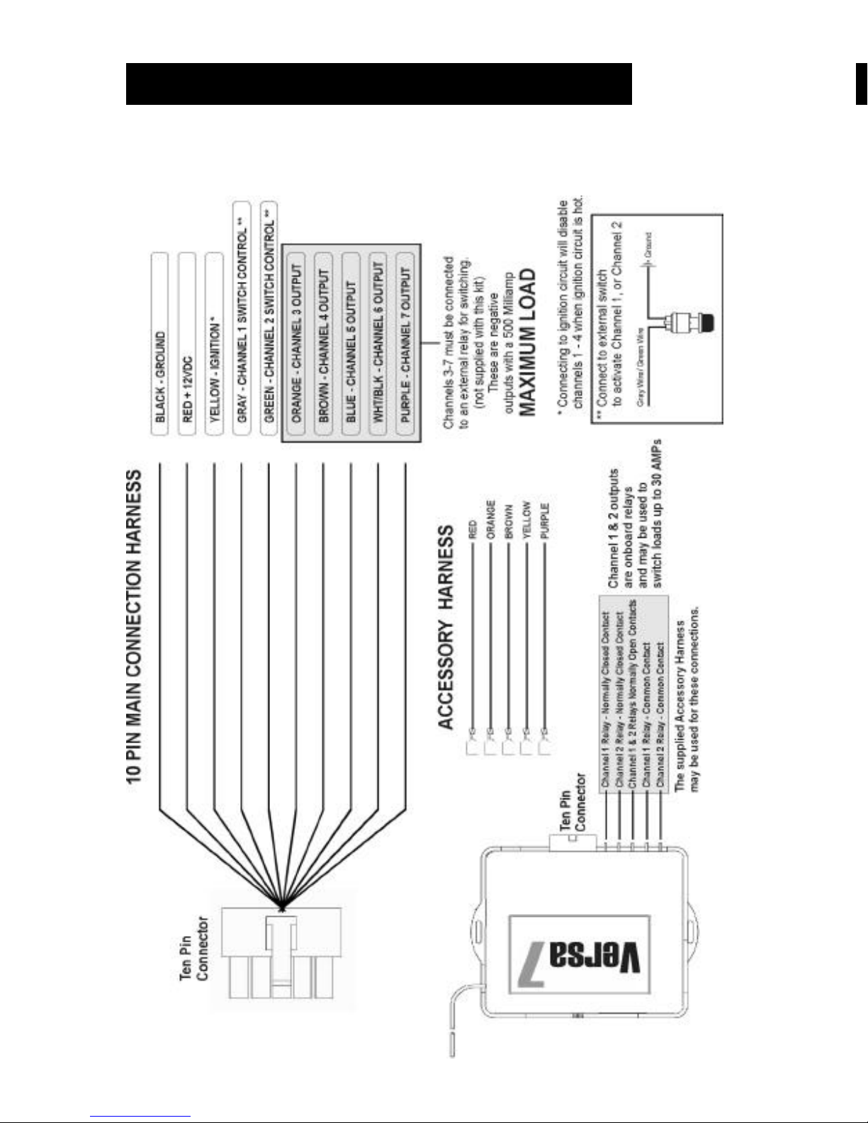
Wiring Harness Information
See the diagram below for wiring harness and connections information.
Page 5
TYPICAL WIRING
Channels 3—7 Optional Output Relay Wiring
Positive and Negative Output Variations
Typical Wiring Diagrams
The next several pages contain a number of typical applications for
the Versa7 remote control system.
Page 6
Page 7
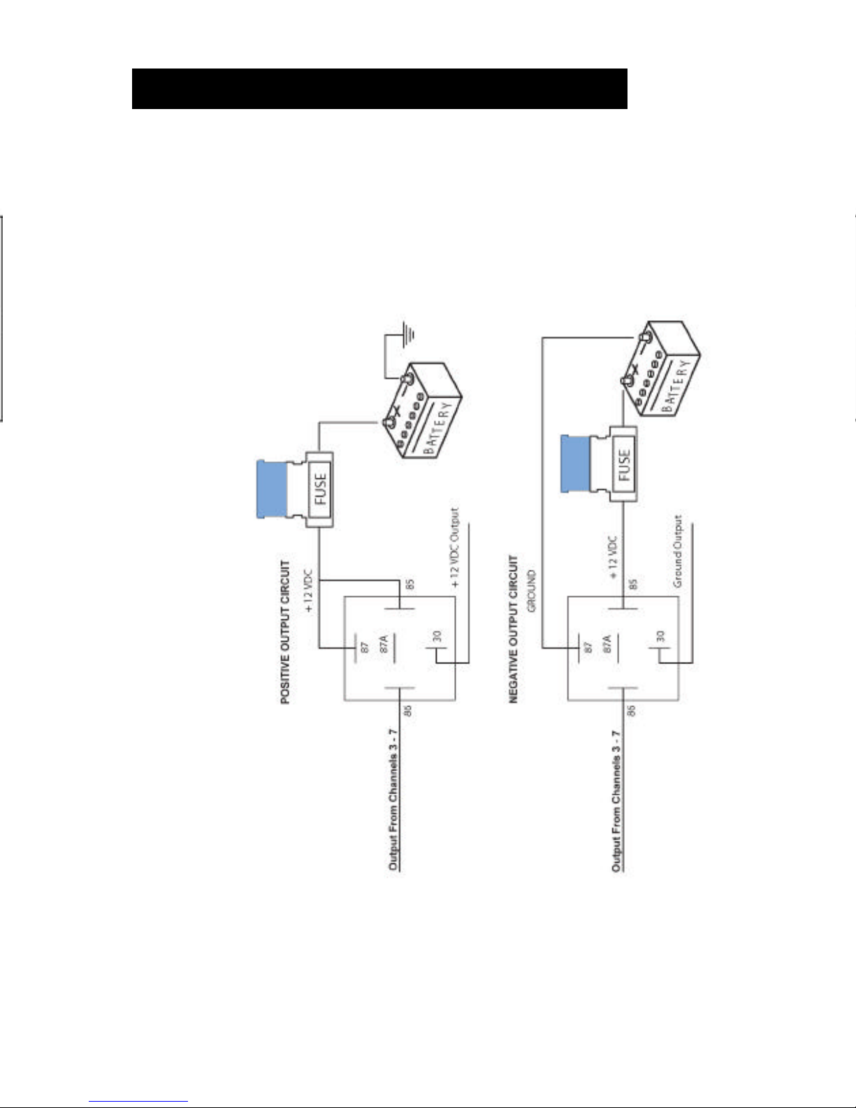
TYPICAL WIRING
Channels 3—7 Optional Output Relay Wiring
Positive and Negative Output Variations
Typical Wiring Diagrams
The next several pages contain a number of typical applications for
the Versa7 remote control system.
Page 6
Page 8
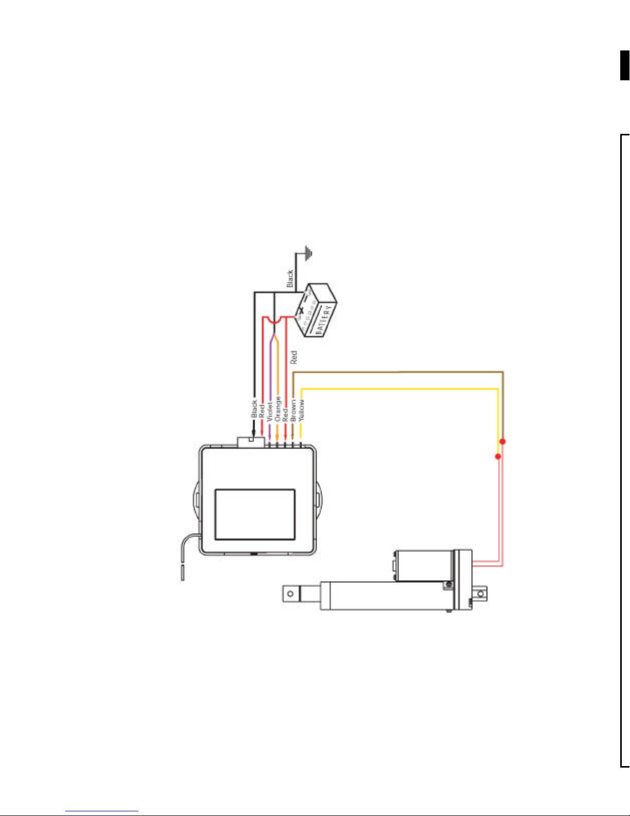
TYPICAL WIRING
Single Motor Reversing Circuit
Channels 1 and 2 Using Onboard Relays
Page 7
DIP Switch Settings
DIP SWITCH FUNCTIONS
DIP
SW
OFF ON
Refer to the table below for DIP switch settings and special functions.
The default position for all DIP switches is OFF.
Page 4
Page 9
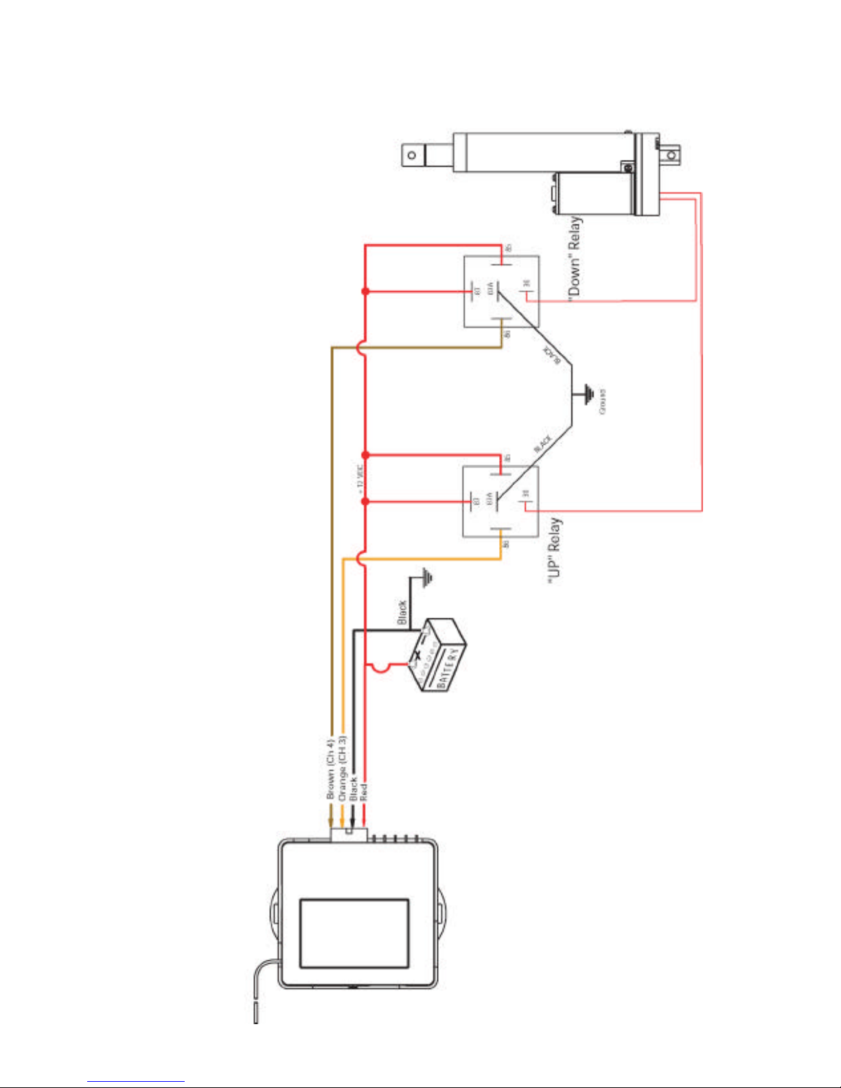
TYPICAL WIRING
Single Motor Reversing Circuit
Channels 3 and 4 Using Optional Automotive Relays
Page 8
Page 10
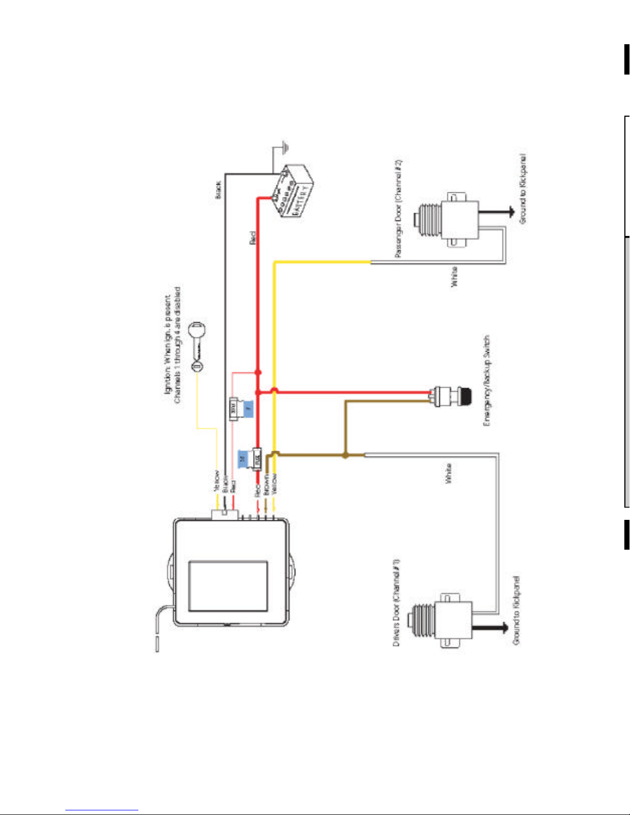
TYPICAL WIRING
Vehicle Door Locking Circuit
Channels 1 and 2 Using Optional Door Lock Solenoids
Page 9
Remote Control Operation
Channel 1: Onboard relay
Channel 2: Onboard relay
Channel 3:
Channel 4:
Channel 5:
Channel 6:
Channel 7:
The remote control supplied with your kit has four buttons, but is capa-
ble of controlling 7 Channels.
Remote Control Programming
Reprogramming the Remote Transmitters:
The remote transmitters are shipped Pre-Programmed. In the event that
a remote transmitter loses the programmed code, or if you wish to add
more remote transmitters, follow these steps:
• Make sure ignition is OFF.
• Locate the programming button located on the side of the receiver
next to the LED.
• Press the programming button 3 times quickly (the LED will light).
• Press Button (1) on each transmitter you want learned in to the re-
ceiver (one at a time). There is a 10 second window to learn all new
transmitters.
• The LED will remain lit for approximately 10 seconds after the last
been recognized.
• Wait for the LED to go out. Then test each transmitter for proper
function.
Page 2
Page 11

Installation Notes
Page 10
Page 12

WARRANTY STATEMENT
Iowa Export-Import warrants this product to be free form defects in material and workmanship for a period of one (1) year from the date of sale
to the original purchaser, and not more than two (2) years form the date
of manufacture. Iowa Export-Import will repair or replace this product
free of charge if, in the judgment of Iowa Export-Import it has been
proven defective within the warranty period. The product should be returned at customer expense, to Iowa Export-Import, 512 Tuttle Street,
Des Moines, Iowa 50309. This warranty does not cover any expense
incurred in the removal and/or reinstallation of the product.
This warranty does not apply to any product damaged by improper installation, accident, misuse, improper line voltage, water (unless the
product is specified to be IP65 compliant), alteration or repairing by
anyone other than Iowa Export-Import.
This warranty is in lieu of other warranties expressed or implied, including warranty of merchantability. No person is authorized to assume for
Iowa Export-Import any other liability concerning the sale of this product.
Seven Channel Remote Control
 Loading...