

Page 1
TM
Express
Resolution Model 265R
Cube
User Guide
_________________________________________
Version 2.0
Oct. 2009
Page 2

Important
ExpressCube™ Countertop User Guide - Copyright© by Global Sensor Systems Inc.
All rights reserved
ExpressCube™ is one of many state-of-the-art product lines designed and manufactured by Global Sensor
Systems Inc.
All information contained in this User Guide is subject to change without notice.
ExpressCube™ products and technology are protected by domestic and international patents both issued
and pending. U.S. Patent No. 7321859 and 7373722 issued.
All ExpressCube™ , SizeIt™ software and firmware is protected by domestic and international copyrights.
ExpressCube™, Global ExpressCube™ , SizeIt™, and the ExpressCube™ logo are registered Trademarks.
Please address any comments or suggestions regarding this user guide to:
Global Sensor Systems
400 Brunel Road,
Mississauga, Ontario
Canada L4Z 2C2
Attention: Documentation
For additional product information or technical assistance refer to our web site: www.expresscube.com
2
Page 3

1.
General..............................................................................................................................5
1.1. Introduction........................................................................................................................5
1.2. Specifications.....................................................................................................................5
2.
Equipment Setup..........................................................................................................6
2.1. Unpacking..........................................................................................................................6
2.2. Location and Placement.....................................................................................................6
2.3. Opening And Securing The Back Sensor Array................................................................7
3.
Electrical Connections..............................................................................................8
3.1. Rear Connecting Panel Layout Summary..........................................................................8
3.2. USB Connection ................................................................................................................9
3.3. Connection of a Handheld Bar Code Scanner ...................................................................9
3.4. Connection settings for hand scanners:..............................................................................9
3.5. Printer Connection...........................................................................................................10
3.6. Connection of the Ethernet LAN (Option) ......................................................................10
3.7. ExpressCube™ External Device Ports.............................................................................11
3.8. Power Adapter Connection..............................................................................................12
4.
Selecting the User Control for the ExpressCube
4.1. ExpressCube™ LCD Controller ......................................................................................13
4.2. Computer Control............................................................................................................13
5.
ExpressCube™ SizeIt
5.1. Summary..........................................................................................................................14
5.2. Minimum Computer Requirements .................................................................................14
5.3. Software Installation........................................................................................................ 14
5.4. Running the Software ......................................................................................................14
6.
ExpressCube™ Countertop Power-up.........................................................................15
6.1. Power-up..........................................................................................................................15
6.2. Initial Power-up System Check .......................................................................................15
7.
User Programming ..........................................................................................................16
7.1. Summary..........................................................................................................................16
7.2. Using the ExpressCube™ Controller Keypad for Programming.....................................16
7.3. Using the PC running ExpressCube™ SizeIt™ for Programming...................................16
7.4. Using the PC running a Third Party Software for Programming.....................................17
7.5. Main Programming Menu................................................................................................17
7.5.1. Alter Dimensional Weight [DIM] Factors................................................................17
7.5.2. Manual / Automatic Operation.................................................................................18
7.5.3. Adjust Beep Duration...............................................................................................18
7.5.4. Set Device Number...................................................................................................18
8.
Operation ..........................................................................................................................20
8.1. Summary..........................................................................................................................20
8.2. Main unit LED indicators ................................................................................................20
8.3. Operation with Third Party Control Software .................................................................21
8.4. Preparation for Measurements.........................................................................................21
8.5. Zeroing the ExpressCube Countertop..............................................................................21
8.6. Placement of the Box for Measurement...........................................................................22
8.7. Verifying That the Parcel is Ready to Measure...............................................................23
8.8. ControllerQuick Setup Guide ..........................................................................................24
8.9. Programming Dimensional Weight [DIM] Factors.........................................................25
8.10. LCD Controller Display...............................................................................................26
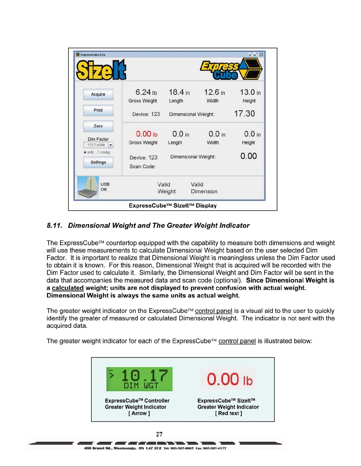
8.11. Dimensional Weight and The Greater Weight Indicator..............................................27
8.12. Acquiring the Measurement Data (Manual Operation)................................................28
™
Software Installation.....................................................14
TM
System...................................13
3
Page 4

8.13.
SEND / PRINT the Acquired Measurement Data (Manual Operation).......................29
8.14. Automatic (ACQUIRE & SEND / PRINT) Operation.................................................29
8.15. Using the ExpressCube™ Countertop as a Weigh Scale Only....................................31
9.
Maintenance.................................................................................................................32
9.1. General.............................................................................................................................32
9.2. Cleaning (Excluding the Sensor Lenses).........................................................................32
9.3. Cleaning the Sensor Lens.................................................................................................32
9.4. Replacing the Sensor Lens...............................................................................................33
10. Troubleshooting...................................................................................................................33
10.1. Summary ......................................................................................................................33
10.2. ExpressCube™ Countertop will not power up.............................................................34
10.3. ExpressCube™ Countertop Controller LCD display is not working...........................34
10.4. ExpressCube™ Countertop PC Controller SizeIt is not working ................................35
10.5. ExpressCube™ Countertop Maintenance Codes .........................................................36
11. ExpressCube Weight Calibration Procedure.......................................................................37
11.1. *** WARNING *** Performed by Authorized Personnel Only................................37
11.2. Calibration Weight.......................................................................................................37
11.3. Procedure......................................................................................................................37
12. Appendix 1 : ExpressCube™ Warranty..............................................................................38
12.1. Statement of Warranty. ................................................................................................38
12.2. Terms and Conditions of Warranty..............................................................................38
12.3. Conditions Which Void Warranty................................................................................ 39
13. Appendix 2: Dimensional Weight & DIM FACTOR..........................................................40
13.1. The Importance of Volume and Weight of Cargo for Transportation..........................40
13.2. Dimensional (Volume) Weight....................................................................................40
13.3. DIM Factor (Dimensional Weight Factor)...................................................................41
13.4. Using DIM Factor (Dimensional Weight Factor) ........................................................41
13.5. Dim Factor Conversion Between in3/lb and cm3/kg.....................................................42
4
Page 5

Page 6
2.
Equipment Setup
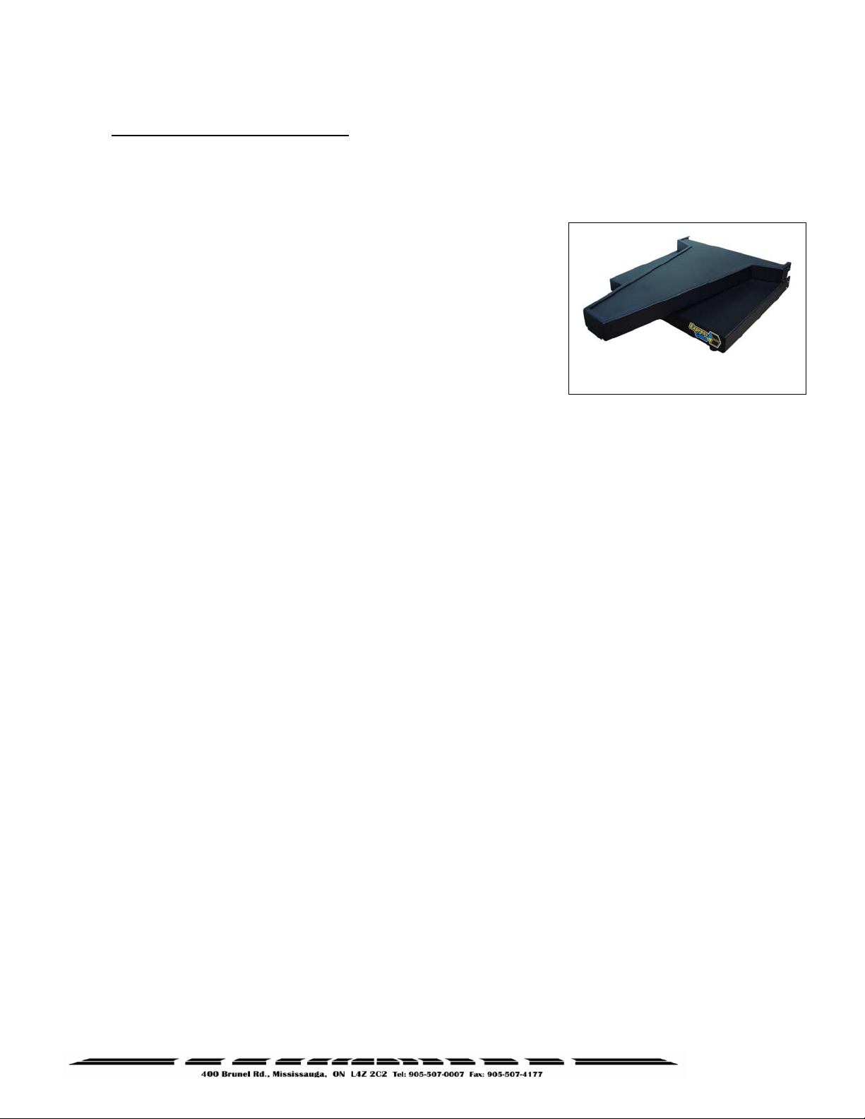
2.1. Unpacking
The ExpressCube countertop unit is shipped with the back of the
unit folded onto the platform. Carefully remove the unit from the
packing material and place the unit in the final location prior to
removing the shipping brackets that secures the back to the top
platform.
Unscrew the leveling feet until approximately one-half inch is
extended from the bottom of the unit. This will allow maximum
flexibility in leveling the unit.
The ExpressCube countertop unit may be provided with optional display and connecting hardware.
It is important to review the equipment list provided in the shipping container to ensure that all items
have been removed prior to disposal of the shipping container.
"
With the protective shipping brackets removed, care must be taken not to subject
the folded back assembly to any twisting or impacts that could harm the hinge assembly.
ExpressCube Shipping / Storage
2.2. Location and Placement
Refer to the specifications to obtain the outside dimensions of this model of ExpressCube countertop
unit. This unit should be placed on a countertop or table that has a surface area that is equal or
greater to the physical dimensions referred to in the specifications. It is important for accurate
weight measurements that the surface is reasonably level, flat and stable.
Ensure that the area selected for the ExpressCube countertop unit is free from objects that could
touch the unit and that there is adequate space to place and measure packages without obstruction.
The ExpressCube countertop unit should be located within four feet of a power source. Verify with
the specifications and the power adapter shipped that the power source and the ExpressCube
power adapter are compatible.
6
Page 7
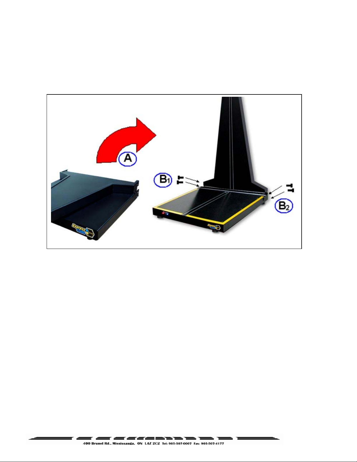
2.3. Opening And Securing The Back Sensor Array
Refer to the diagram below to raise and secure the back sensor array from the shipping / storage
position. Inspect the device before starting the procedure to ensure that all bindings and/or shipping
restraints have been removed.
A. Carefully lift up the rear sensor panel 90° to the surface of the platform until the holes at the
rear of both parts of the assembly line up.
B. Insert the supplied four locking bolts into the back assembly and tighten.
"
It is important to put the locking bolts in without cross threading. Although the back
assembly requires little effort to be held in place, it is recommended that one person hold the
back sensor panel in place while a second person installs the locking bolts.
7
Page 8
3.
Electrical Connections
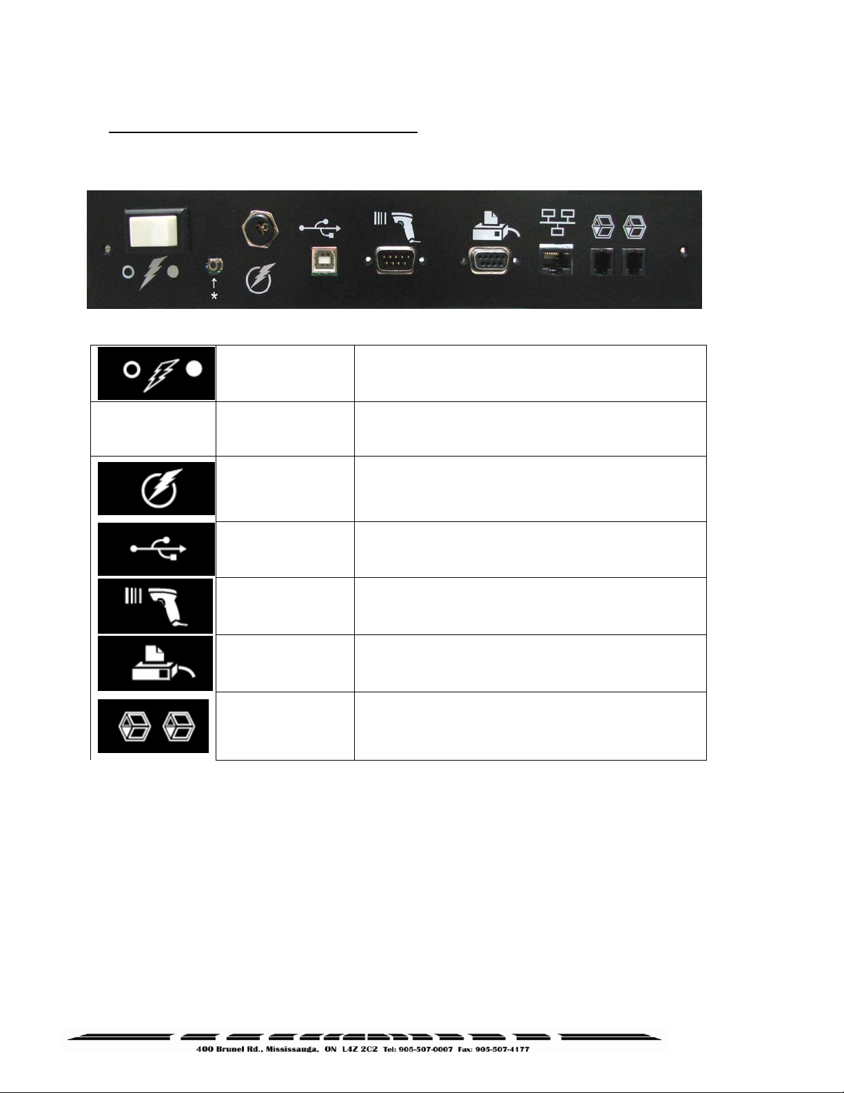
3.1. Rear Connecting Panel Layout Summary
Symbol Function Description
Switches ExpressCube unit ON / OFF
*Authorized Personnel Only* Removal or damage to
the calibration seal voids certification approvals
The ExpressCube™ universal power adapter includes
4 power connections and has the following world
safety approvals: UL / ULC, CE, PSE, BS, GS, FCC,
SAA
*
(unmarked)
Power Switch
Calibration
Power Adapter
USB
This USB port can be used by a local PC to
Operate and collect data from the ExpressCube™ unit.
Hand Scanner
Connect to handheld scanner (not supplied).
The port is a male RS-232 serial interface.
RS-232 male port provides ASCII data output for either
Printer
External Devices
"
Connect all the appropriate connectors prior to connecting the power adapter and
activating the device.
"
The ExpressCube ™ countertop unit is designed such that there is space to connect
and run the cables from the rear connector panel. Do not use this space to bunch and store
excess cable as the movement of the platform could be restricted by cable contact.
a printer or direct data logging onto a hard drive via a
local PC application (not supplied).
These connectors are used to connect ExpressCube™
external devices such as the customer display or
control box.
8
Page 9
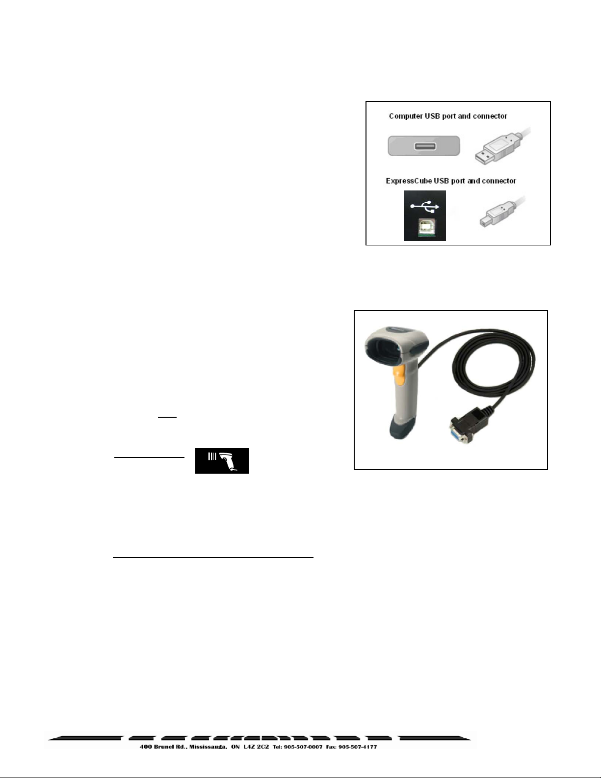
3.2. USB Connection
The ExpressCube™ countertop series of dimensioning
devices are equipped with a USB connection to interface
to a local computer. The USB connection allows the
computer to control and capture data from the
dimensioning device. The USB is fully compatible with
USB 2.0 computer ports.
Connect the cable as indicated in the diagram.
"
ExpressCube™ SizeIt™ must be installed in the
computer before the USB interface can be used.
Refer to the ExpressCube
™
SizeIt™ installation section for more details.
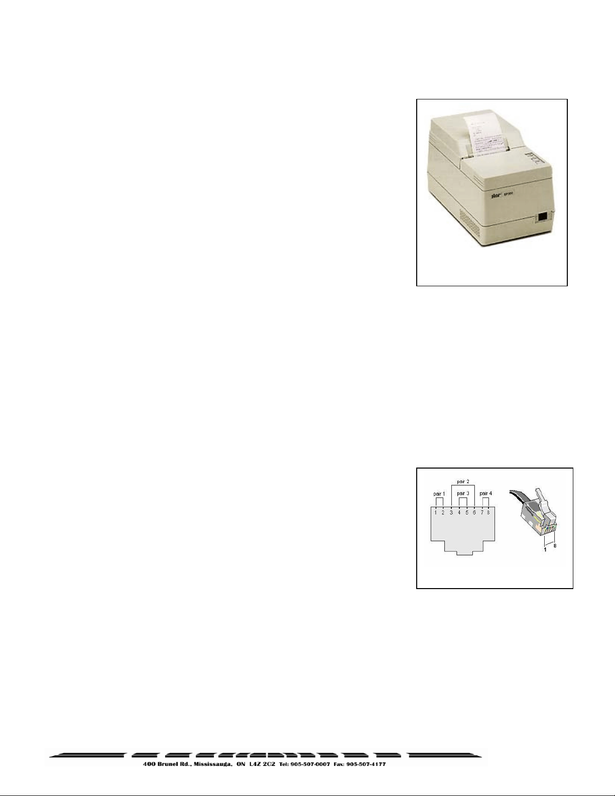
3.3. Connection of a Handheld Bar Code Scanner
The ExpressCube™ countertop unit has a dedicated
male RS-232 serial port for use with a handheld bar
code scanner. [Handheld scanner not supplied] The
RS-232 connector should be securely connected to the
appropriate connector on the ExpressCube™
countertop.
"
There are two RS-232 connectors on the
connector panel but each one serves different
purposes. Be sure to use the connector identified
for the hand scanner
"
The ExpressCube™ countertop unit has programming options that can utilize the
trigger of the handheld scanner to activate data collection and processing. Refer to the
Operators Program Menu for more details.
3.4.
1) Connection port – RS-232
2) Baud rate - 9600
3) Parity – none
4) Data bits – 8
5) Stop bit – 1 and add a suffix of a CR LF (Carriage Return Line Feed)
Connection settings for hand scanners:
.
Sample RS-232 Hand Scanner
9
Page 10
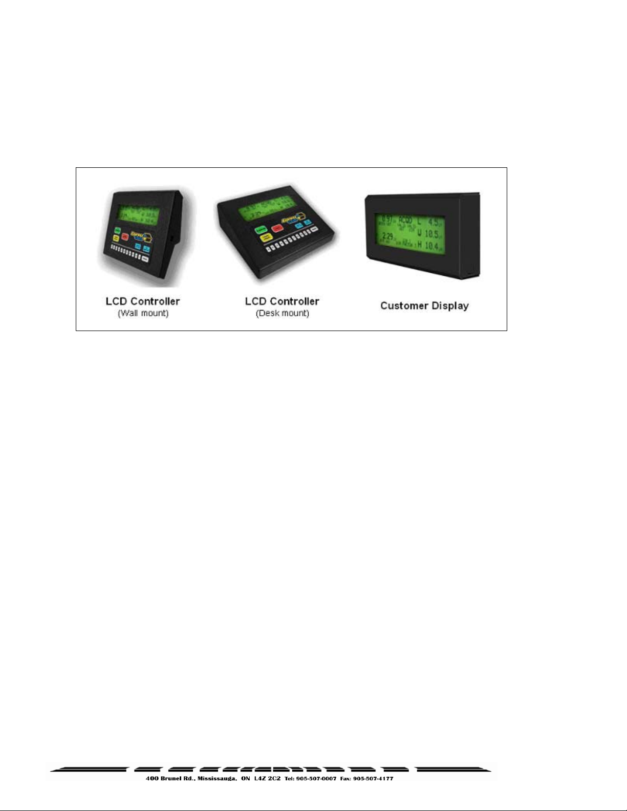
3.5. Printer Connection
The ExpressCube™ countertop unit is equipped with a female
RS-232 serial printer port. The port is activated when the
ExpressCube™ countertop unit has acquired data through a
successful measurement. Upon receiving a ‘Print’ command, the
printer port will deliver the data in an ASCII format that is
terminated with a line feed and carriage return. The RS-232
connector should be securely connected to the appropriate
connector on the ExpressCube™ countertop.
"
The ExpressCube countertop unit has been specifically
set up using the Star SP-300 Series ASCII model. While most
ASCII RS-232 printers follow virtually identical data formats,
the user is responsible to assure their selected printer is
compatible to the Star-300 series format.
"
For detailed description of the data format to the printer, refer to the Technical Data
Summary in the appendix of this manual.
Star SP-300
3.6. Connection of the Ethernet LAN (Option)
"
A physical LAN port has been accommodated on the rear connector panel of all
ExpressCube countertop units but the necessary support hardware & software will not
be introduced unto t he 3
The ExpressCube™ countertop unit at this time will be equipped
with an active 10 Base T Ethernet LAN port. The user will be able
to send acquired measurement data to a remote server for
recording and/or billing purposes. The LAN device will only be
used to record package data and is not intended to be used to
control the ExpressCube™ countertop functions.
The LAN connector is a standard RJ-45 connector. The LAN port
configuration is programmed through the USB connector using the
ExpressCube™ countertop maintenance software. The port
configuration is recorded on non-volatile memory and will remain until reprogrammed through the
USB connector.
rd
quarter of 2009.
RJ-45 Connector
10
Page 11
3.7. ExpressCube™ External Device Ports
The ExpressCube™ external ports are high-speed data and power ports that are used to connect to
optional ExpressCube™ equipment. There are two external device ports on the rear connector
panel. The two ExpressCube™ external devices supported by these ports are the control unit and
the customer display unit as illustrated below.
T
The ExpressCube™ Controller has a reversible mounting plate that allows the controller to be
converted from a desk mount (as shipped) to a wall mount. To change the configuration, remove
the four screws holding the bracket. Rotate the mounting bracket 180° and secure with the same
four screws.
The ExpressCube™ external device ports use RJ-11 four wire connectors. Place or mount the
device to be connected in the location that it will be used. Insert the RJ connector until an audible
click is heard. Carefully route the cable and insert the RJ-11 connector into either one of the two
ExpressCube™ external device ports.
"
The RJ-11 is a popular jack used by manufacturers for a variety of different devices and
purposes. DO NOT INSERT ANY OTHER MANUFACTURED DEVICE EQUIPPED WITH A RJ-11
INTO THE EXPRESSCUBE DEVICE PORT. The attempted use of this RJ-11 port for any
device other than an ExpressCube™ device can cause internal damage and void the
warranty.
"
The ExpressCube™ external device ports provide low voltage power to operate the
circuits and backlit LCD displays of the external devices. Care should be taken to ensure that
no foreign objects are inserted into these ports.
11
Page 12
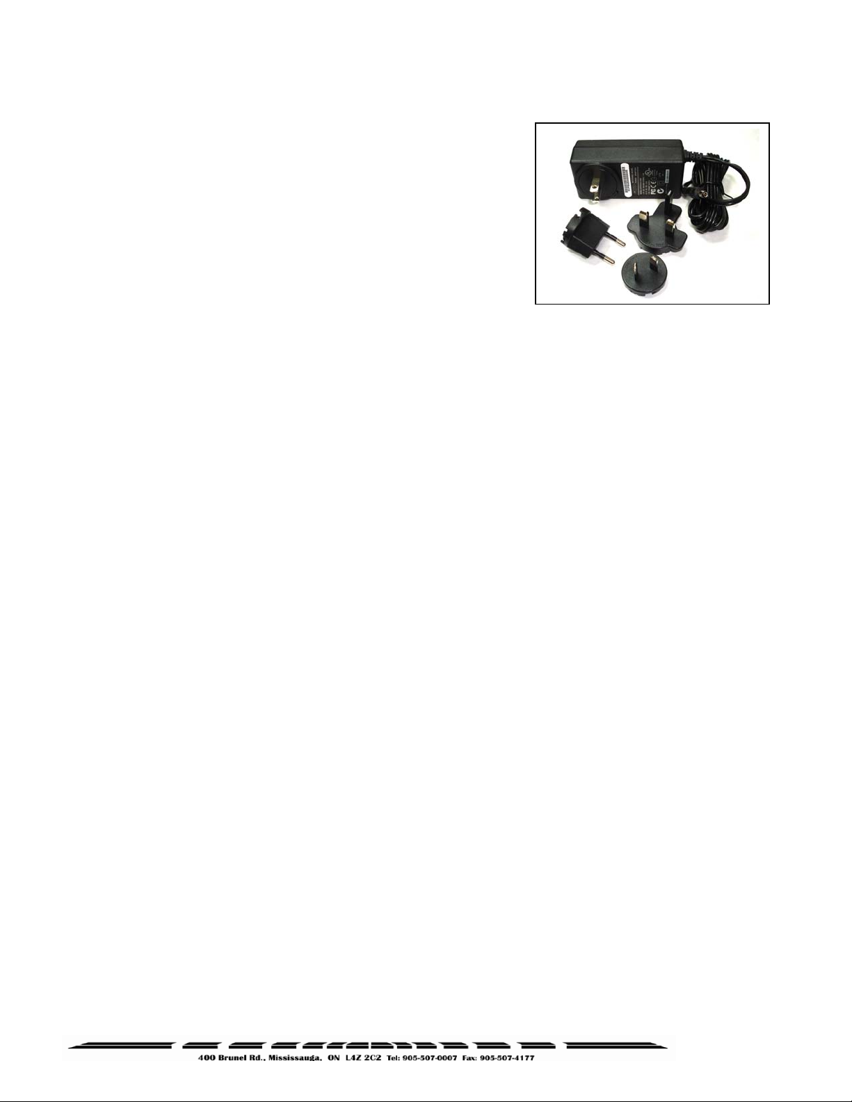
3.8. Power Adapter Connection
After connecting the appropriate connectors as detailed in
Sections 3.1 to 3.7, insert the power adapter plug into the
ExpressCube countertop rear connector panel.
The cable from the rear of the unit to the adapter should be
free from obstruction and located to prevent accidental
removal from ExpressCube or the outlet. Securely connect
the power plug into an electrical outlet.
"
Use only ExpressCube power adapters with the ExpressCube countertop unit.
"
The power adapter must have unrestricted airflow around it. Do not wrap or enclose the
power adapter.
12
Page 13

4.
Selecting the User Control for the ExpressCubeTM System
The ExpressCube™ Countertop system must have an operator controller to perform the
measurement functions. The ExpressCube™ Countertop system can be controlled either by a
desktop computer using the USB interface or by using the ExpressCube™ LCD Controller. If a
display is required to monitor the ExpressCube operation, it is recommended to use the customer
display.
4.1. ExpressCube™ LCD Controller
The use of the ExpressCube™ LCD Controller only requires the appropriate electrical connection as
described in the section above. The installation of the SizeIt™ software is not required. Proceed to
the power-up section of this user guide.
4.2. Computer Control
The use of a computer to control the ExpressCube™ Countertop system will require the installation
and use of the SizeIt™ software. Connect the USB cable as previously described and follow the
instructions outlined in the ExpressCube™ SizeIt™ Software Installation section of this guide.
"
In this User Guide, the term ‘control panel’ [underlined] will reference the device used to
control the ExpressCube
computer running SizeIt
"
When the ExpressCube™ LCD Controller is used to control the ExpressCube™
Countertop system, the USB port is still active and can be used by a trained technical or
administration personnel to service the unit.
™
Countertop System. ( i.e. ExpressCube™ LCD Controller or local
™
software )
13
Page 14

5.
ExpressCube™ SizeIt™ Software Installation
5.1. Summary
The ExpressCube™ SizeIt™ software allows a local computer to operate and gather data from the
ExpressCube™ countertop unit with the USB port. This software must be installed and the USB
connected prior to powering-up the ExpressCube™ countertop unit. The software is not required if
the ExpressCube™ controller is used to control the countertop unit.
5.2. Minimum Computer Requirements
• Minimum 512 meg of available RAM
• Pentium IV or better @ 2.0 GHz or better
• Windows XP operating system
• CD-ROM drive
• Java version 1.5.0_06 or later
5.3. Software Installation
1. Close down all applications currently running on the PC.
2. Insert the CD program disk into the CD-ROM drive of the computer.
3. Click the Windows ‘START’ button and select ‘RUN’
4. Use the browse key to locate and select the ‘set-up’ file on the CD-ROM drive
5. Run the selected file.
Note
- if you encounter recurring problems with the operation
of the program, un-install Size-It and re-install.
"
The person installing the software should have the appropriate system permissions to
install the software, this will vary for the system & location, and this can be especially critical
for Windows XP.
5.4. Running the Software
Use either the Start
to begin the SizeIt™ program. The program will
open the control page as illustrated to the right.
Select the highest “com number” on the drop
menu to engage the USB (choice shown as
‘com 7’ in example at right).
The USB port will remain off when the
ExpressCube™ countertop unit is not powered.
The ‘Set-up’ key will not work until
communications is established on the USB link.
/
Program or Desktop menus
14
Page 15

6.
ExpressCube™ Countertop Power-up
6.1. Power-up
Locate and activate the power switch located on the rear panel. The ExpressCube countertop
must not have anything on the platform when the power is switched on. Almost instantly, the
power [RED] indicator LED will begin to flash and then remain lit. During the brief time that the LED
is flashing, power has been applied to the main computer and it has started it’s program initiation.
The steady LED indicates that the power is on, the sensors are calibrated and the main computer is
operating properly.
"
The four indicator LEDs on the front of the ExpressCube countertop unit are intended to
give the user a quick summary of the current operation of the unit. These LEDs are controlled
by the measuring device and are not affected by the controller ( including third party software
). Always refer to the control panel
6.2. Initial Power-up System Check
The motherboard enters a self-diagnostic routine in which errors are reported in a diagnostic log.
The results of the diagnostic routine contain a summary of the polling the different subsystems of the
ExpressCube™
This section just briefly describes the system checks carried out by the motherboard as it is powered
up. It is carried out almost instantly and has no visible effect on the operation of the unit.
1) SYSTEM CHECK – The system verifies the proper operation of on-board components.
2) CONFIGURATION – Each power up cycle, the motherboard polls and assigns addresses to the
Integrated Transceiver Array which perform the package measurements.
3) LOAD CELL – The motherboard verifies the operation of the load cells and programs the filters
used in the digital interface.
Any irregularities are recorded as maintenance codes and can only be accessed by a software
header in the motherboard.
display for detailed operational status.
"
The control panel will be ready for operation after the system check is performed within
a few milliseconds of power-up. If the display or system does not appear to be functioning,
please refer to the troubleshooting section. DO NOT ATTEMPT TO OPEN THE SYSTEM.
15
Page 16

7.
User Programming
7.1. Summary
The ExpressCube™ countertop has a simple programming menu that allows the user to program the
following characteristics:
• Program dimensional weight factors.
• Handheld bar code scanner Acquire & Print synchronization.
• Adjust audible (beep) warning characteristics.
• Set device number.
Generally the user programming is set once and rarely requires adjustment. All programmed
selections are stored and will remain until changed through the user programming.
"
retained even if the ExpressCube countertop system is not powered.
7.2. Using the ExpressCube™ Controller Keypad for Programming
The ExpressCube™ Controller keypad has been
designed to easily make adjustments using the
user-programming feature. Respond on the
numeric keys as directed by the display to make
a menu selection.
Use the UNITS key to toggle between in/lb and
cm/kg. Use the ACQUIRE button to enter a
typed numerical value.
User programmed features and data is stored on non-volatile memory and will be
7.3. Using the PC running ExpressCube™ SizeIt™ for Programming
The programming menu can be easily accessed from the PC running SizeIt™ software program by
clicking the Settings [Prog] key using the mouse cursor. All menu selections can be selected by the
mouse and normal PC keyboard functions can be used to edit data entries.
16
Page 17

7.4. Using the PC running a Third Party Software for Programming
The ExpressCube™ countertop unit has an API interface which allows third party software to
operate, acquire data and utilize the user program feature set. Refer to the manufacturer’s
instruction on the use of programming features with the third party software.
"
***IMPORTANT*** Third party software will have access to all data from the
™
ExpressCube
dimensioning factor and handheld scanner codes; however
use the ExpressCube
only. If the third party software determines dimensional weight, only accessing the third
party software can change dimensional weight factors.
countertop data including measurements, units, dimensional weight,
, the software manufacturer may
™
countertop to measure, weigh and collect handheld scanner codes
7.5. Main Programming Menu
7.5.1. Alter Dimensional Weight [DIM] Factors
Selecting this menu allows the user to review or change any of the four dimensional factors
used by the ExpressCube™ countertop computer to calculate dimensional weight.
Sub-menu:
1. (Dim Factor) [Units]
2. (Dim Factor) [Units]
3. (Dim Factor) [Units]
4. (Dim Factor) [Units]
5. BACK
Select the dim (dimensional weight) factor that you wish to change and verify the correct
units before entering the new value.
"
The dimensional weight factors can only have four digits with the last digit
representing units or tenths. (e.g. 000.0 to 9999) Any entry of four or less digits will be
assumed whole numbers unless a decimal is used. The maximum dim factor setting is
276 in3/lb
"
ExpressCube
match the units that are used.
The dimensional factor displayed and output from the unit will always match the units
that the measurements were taken.
The Dim Factors are displayed in the units that they were originally input but the
™
countertop computer will convert the dimensional weight factors to
17
Page 18

7.5.2. Manual / Automatic Operation
This selection provides an option for an automatic recording of the measurement data after
the data is collected. The automatic operation can significantly speed the measurement
process and is used when there is no requirement to review acquired measurements before
recording them.
Manual Operation
user will press the Acquire key or (if equipped) the trigger of the handheld scanner. The
acquired measurement data will be displayed but the user must activate the SEND/ PRINT
key to record the data. Removal of the package from the platform will clear any acquired
measurements and prepare the device for a new measurement sequence.
Automatic Operation
the user will press the trigger of the handheld scanner (if equipped). The ExpressCube™ will
record the measurements and automatically send the acquired data with the bar code as if
the SEND button had been pushed. All acquired data will remain in the display until the
parcel is removed from the ExpressCube™ platform.
Sub-menu:
MANUAL / AUTOMATIC OPERATION
1. MANUAL <SELECTED>
2. AUTOMATIC
3. GO BACK
4. EXIT
Press the appropriate number to select the desired operation mode. The current selection
will be indicated by the <SELECTED> beside it. After verifying the correct selection, use
EXIT function to return to the main menu.
: If the ExpressCube™ is in a ready state to record the measurement, the
: If the ExpressCube™ is in a ready state to record the measurement,
7.5.3. Adjust Beep Duration
This selection will permit the user to adjust or turn off the warning beep tone.
Sub-menu
SELECT 0-9
CURRENT SELECTION 6
Enter a digit from 0 (off) to 9 to set the audible tone. The current selection will be updated
and the selection confirmed in large format. After the confirmation, the program will exit to
the main menu.
7.5.4. Set Device Number
18
Page 19

This selection allows the user to set a device number for the ExpressCube™ countertop unit.
The device number is sent with each data message of acquired data. This device number
can be used to track a box through a facility.
Sub-menu
CURRENT DEVICE NUM XXX (000-999)
If device number requires change from the current number, type in the three-digit new device
number. When the new device number is confirmed on the display, the program will
automatically exit to the main menu.
Pressing the PROG key will exit the menu without changing the device number.
19
Page 20

8.
Operation
8.1. Summary
The ExpressCube™ countertop is a very accurate MDMD (Multi-Dimensional Measuring Device) that
is capable of measuring cuboidal (rectangular/square) boxes with great precision. The
ExpressCube™ countertop has built in controls to prevent erroneous readings that cannot be altered
by third party software control. Even with these built in controls, the user must exercise care to
follow these guidelines:
• Boxes cannot exceed the dimension and weight listed in the specifications.
• Boxes must be cuboidal ( i.e. rectangular or square).
• Severely damaged packages or packages covered by excessive mud or ice can cause errors
for both dimensions and weight.
• Both the platform and the package being measured must be free from physical contact with
surrounding objects.
• Place objects on the platform – do not drop packages onto the platform
"
Keep the platform clean and free of dust build up to ensure optimum operating
performance.
.
8.2. Main unit LED indicators
The main unit LED indicators are a set of four LEDs mounted on the
front of the main platform of the ExpressCube™ countertop. They
give an accurate status of the ExpressCube™ countertop main
computer and are unaffected by third party software.
• Red – Power
unit has power.
• Yellow – Valid Dimension
indicates that the ExpressCube™ countertop has measured
a parcel placed on the platform.
• Green – Valid Weight
that the ExpressCube™ countertop has weighed a parcel
placed on the platform.
• Blue – Zero
ExpressCube™ countertop is in a zero (no-load) condition.
"
The ExpressCube™ countertop will not attempt any new measurement until the unit has
reached a zero condition after the removal of the previous package. The Yellow and Green
LED indicators will remain in the ACQUIRED state until a zero condition is achieved after the
last recorded measurement.
– A steady illumination indicates that the
– A steady illumination
– A steady illumination indicates
- A steady illumination indicates that the
20
Page 21

8.3. Operation with Third Party Control Software
If this ExpressCube™ countertop unit is used with third party software (i.e. not an ExpressCube™
control panel
party software.
It is not possible for the third party software to affect the integrity of the measurements output from
the ExpressCube™ countertop. The acquired data is output only if the correct procedures have
been followed (zero condition, etc) and the output data itself is packaged with all related
measurement parameters in the data packet. However, it can be difficult for the user to initiate this
sequence without a full understanding of the software being used.
"
It is recommended that third party software users read the following operation
procedures for the ExpressCube
measurement is identical and helpful points presented in the manipulation of the package
will be useful.
), it is important that the user studies the documentation that is supplied with the third
™
control panel. The procedure for obtaining a
8.4. Preparation for Measurements
The ExpressCube™ countertop unit should be powered up and the ExpressCube™ control panel
display finished the initial system check. Prior to starting measurements, it is recommended that the
platform and sensors be wiped with a damp rag to remove any accumulated dirt and/or debris.
Select the units and dimensional factor (if used) for measuring the parcel.
8.5. Zeroing the ExpressCube Countertop
The ExpressCube Countertop will not record any measurements unless the platform has recorded
the Zero condition (weight of the platform in an idle condition) prior to a package being placed on the
platform. After verifying that the measurement platform is empty, press the ‘ZERO’ function button
on the ExpressCube™ control panel
The Blue LED under the platform will light and a zero condition will be indicated by the word ‘ZERO’
on the display of the ExpressCube™ control panel
ExpressCube™ control panels
ExpressCube™ Controller Display
.
. The Zero condition display for both of the
is illustrated below:
21
Page 22

ExpressCube™ SizeIt™ Display
8.6. Placement of the Box for Measurement
Place the box to be measured flush against the
back of the ExpressCube™ countertop such that
one side of the box is in contact with the rear face.
The orientation of the box is arbitrary as long as it:
• Sits over the center array
• Is flush (contact) to the back
• Sits within
The illustration shows an example of a box
ready for measurement and indicates how
the dimensions will be recorded.
the yellow guide lines
22
Page 23

8.7. Verifying That the Parcel is Ready to Measure
Once the box is in place, the ExpressCube countertop unit will resolve the weight and dimensions.
A successful measurement is indicated by the steady illumination of the yellow LED (valid
dimension) and the green LED (valid weight) on the front of the platform. The ExpressCube control
panel will also have valid measurement indicators with the actual measurements displayed.
If the weight has not been resolved, the problem could be caused by:
• The box weight exceeds specifications. Weight will read ‘OVER’
• The ExpressCube countertop was not in a zero condition prior to the box placement on the
platform.
• The ExpressCube countertop is undergoing vibrations or movement that prevent weight
resolution.
If the dimensions cannot be resolved, all
within the yellow guidelines and there is not a valid dimension obtained, the problem could be
caused by:
• The box dimension does not fall between the minimum and maximum the specifications.
• The box is not flush against all three dimensional arrays.
• There is excessive dirt or an object blocking the measuring arrays.
dimensions will read ‘N / A’. If a cuboidal package is placed
"
If the ExpressCube™ countertop is unable to resolve a valid dimension, it will behave as
a weigh scale. In this condition, acquiring a measurement will only record the weight and a
scan code (optional).
"
If the ExpressCube™ countertop is equipped to dimension only, the unit will not record
a measurement unless a valid dimension is obtained.
The ready to acquire condition (valid measurements) display for both of the ExpressCube™ control
panels is illustrated below:
ExpressCube™ Controller Display
23
Page 24

8.8. Controller Quick Setup Guide
1
Carefully remove the Controller
from the packing material and
place the unit in the final
location.
2
Place the device to be
connected in the location
that it will be used.
3
Carefully route the cable
and insert the RJ-11 connector
into either one of the two
ExpressCube external
device ports.
4
The control panel will be ready
for operation after the system
check is performed within a few
milliseconds of power-up.
24
Page 25

8.9. Programming Dimensional Weight [DIM] Factors
Selecting the program button ( PROG ) allows the user to review or change any of the four stored DIM
factors used by the ExpressCube
Select the DIM factor that you wish to change and verify the correct units of measure (Metric or Imperial)
before entering the new value.
1) Select an Option
(
To program, press and hold “PROG” 1 second)
1. Change DIM Factor
2. Change Scanner Trigger
3. Change Device Number
4. Exit (or Press “PROG”)
2) Select the Unit Type
(Press buttons firmly when selecting)
1. Metric
2. Imperial
3. Go Back
4. Exit (or Press “PROG”)
3) Select the [
Imperial ] DIM Factor to change
1. 154.9
2. 192.0
3. 145.0
4. 105.1
5. Go Back
6. Exit (or Press “PROG”)
4) Input New DIM Factor to Replace “current number”
“New number”
5) Accept New DIM Factor “xxx.x”
1. Yes
2. No
The dimensional weight factors can only have four digits with the last digit representing units or
tenths. (e.g. 000.0 to 9999) Any entry of four or less digits will be assumed whole numbers unless a
decimal is used. The maximum dim factor setting is 276 in3/lb
TM
countertop computer to calculate dimensional weight.
25
Page 26

8.10. LCD Controller Display
LCD display functions are highlighted here to acquaint you with the
measurement processes.
A) Gross weight is shown with one decimal figure which conforms to the
current measure unit specification.
B) The letters “RES” will appear while the system is resolving a “Valid weight”
and / or a “Valid dimension”.
C) After a box has been placed on the platform for measurement, the “Acquire” button
can be pressed at any time while the system is still in the “RES” (resolve stage). This
allows faster weight and dimension acknowledgement and eliminates the need to
wait for the “Valid” numbers to settle in first, as required previously.
D) Calibrate DIM Banks - A very important addition to the capability of the new updated
Diagnostic version enables the operator to perform the sensor array bank calibration.
This procedure can be a valuable addition to a regular maintenance program as the
calibration will help the sensor measurements to run at peak performance and correct
any unexpected aberrations on the lens that can affect accurate readings. To access the
Calibration DIM Banks feature, press “PROG” on the keypad, then select number “5” .
Then follow the instructions on the display.
26
Page 27
Page 28

y
8.12. Acquiring the Measurement Data (Manual Operation)
To record the measurement of the box on the ExpressCube™ countertop, activate the ACQUIRE
button on the ExpressCube™ control panel
activate the Acquire sequence while reading the bar code on the package. The acquired data will be
displayed on the ExpressCube™ control panel
If the data is not recorded, an audible beep will be heard. The user should refer to Section 8.7. and
verify that the box is properly positioned for measurement.
"
If the box is removed from the platform without the SEND/PRINT button activated, the
acquired data will be lost and the ExpressCube
condition to start a new measurement.
"
After a successful measurement is acquired, the valid measurement indicators both on
the front panel of the main unit and the ExpressCube
measurement procedure is started.
Displayed below is the successful acquired measurement (ACQD) for both control panels.
ExpressCube™ Controller Display
ExpressCube™SizeIt™Displa
. Alternatively (if equipped), the handheld scanner will
display.
™
countertop must return to the zero
™
control panel are held until a new
28
Page 29

8.13. SEND / PRINT the Acquired Measurement Data (Manual Operation)
The acquired measurement data can be sent to the printer and any other devices or ports connected
to the ExpressCube™ countertop by activating the SEND/PRINT button on the ExpressCube™
control panel
The ExpressCube™ countertop will attempt to successfully send the acquired measurement data
through the various data ports until the ExpressCube™ countertop returns to a zero condition. Any
measurement data that has not been sent or printed will be cleared from the transmission buffer
when the ExpressCube™ countertop is in the zero condition.
"
The ExpressCube™ control panel display will continue to hold the acquired data until
the box is removed.
. The SEND / PRINT button will only respond once for every measurement taken.
8.14. Automatic (ACQUIRE & SEND / PRINT) Operation
This feature can be used when the AUTOMATIC OPERATION option is selected in the user
program (Section 7.5.2). The ExpressCube countertop must be ready for acquiring a measurement
(as described in Section 8.7.). To acquire and
ExpressCube™ countertop, the handheld scanner will activate the Acquire and
sequence while reading the bar code on the package. The ExpressCube countertop will receive the
data from the handheld scanner and append it with the acquired measurement data. The acquired
data will be displayed on the ExpressCube™ control panel
The ExpressCube™ countertop will attempt to successfully send the acquired measurement data
through the various data ports until the ExpressCube™ countertop returns to a zero condition. Any
measurement data that has not been sent or printed will be cleared from the transmission buffer
when the ExpressCube™ countertop returns to a zero condition.
If the measurement data is not acquired, an audible beep will be heard. The user should refer to
Section 8.7. and verify that the box is properly positioned for measurement.
record the measurement of the box on the
SEND / PRINT
display.
"
The ExpressCube™ control panel display will continue to hold the acquired data until
the box is removed.
"
After a successful measurement is acquired and sent, the valid measurement indicators
™
both on the front panel of the main unit and the ExpressCube
new measurement procedure is started.
29
control panel are held until a
Page 30

The successful acquired and sent measurement display for both of the ExpressCube™ control
panels is illustrated below:
ExpressCube™ Controller Display
ExpressCube™ SizeIt™ Display
30
Page 31

8.15. Using the ExpressCube™ Countertop as a Weigh Scale Only
The ExpressCube™ countertop can be used to measure the weight of non-cuboidal objects or
cuboidal objects that physically exceed the dimensioning specifications of the machine. This feature
allows the user to determine weight on courier documentation packs, odd package shapes including
shipping cylinders, etc.
Place the package on the ExpressCube™ countertop platform to physically limit as much package
over-hang as possible. The ExpressCube™ countertop will automatically reconfigure itself as a
weigh scale when an object is detected on the platform that cannot be accurately dimensioned.
The ExpressCube™ countertop unit acting as a weigh scale will indicate ‘N
and calculations based on dimensional measurements. (See illustrations below). Only the device
number, weight and scan code (optional) are recorded during the Acquire sequence.
To acquire and record a weight, use the same procedure and options as described in the previous
sections for obtaining and recording dimensions.
ExpressCube™ Controller Display
/ A’ on all measurements
ExpressCube™ SizeIt™ Display
31
Page 32

9.
Maintenance
9.1. General
The ExpressCube™ countertop unit is a sealed certified device that does not require any internal
periodic maintenance. In the event that the unit has incurred physical damage that may affect the
operation of the unit, it should be sent back to an authorized service center for repair and recalibration.
9.2. Cleaning (Excluding the Sensor Lenses)
To maintain the optimum performance of the ExpressCube™ countertop, the unit should be
periodically cleaned to remove any build-up of dust and dirt. The black metal areas should be
cleaned separately from the sensing strips. Use a damp cloth with a mild detergent and rinse with a
clean damp cloth. Hand pumped sprayers can be used. Apply a non-corrosive cleaner to stubborn
areas but care should be exercised to keep spray from the sensor strips.
"
Do not use any volatile liquids to clean the surface. This is an electronic device and
trapped fumes in the enclosure could be ignited by the electronic circuitry.
"
Do not use any pressurized liquid source (e.g. water hose, steam jet, etc) to clean the
unit.
9.3. Cleaning the Sensor Lens
It is important to keep the sensor lenses clean and free from any debris that may obscure the
package from sensors. Use a soft clean cloth with commercial glass cleaner to clean the surface of
the lens.
"
Do not use abrasive or dry cleaners on the lens.
32
Page 33

9.4. Replacing the Sensor Lens
If a sensor lens becomes foggy (opaque) from wear, cracked or broken it should be replaced. All
three lenses have a cover to permit safe and quick replacement of the lens. The covers are held on
by two screws and there locations are illustrated below.
10. Troubleshooting
10.1. Summary
The ExpressCube™ countertop is a multi-dimensional precision instrument designed to work in a
variety of working environments. The internal assembly is sealed to preserve the integrity of this
measuring instrument. There are a number of problems that may arise that can be addressed
without tampering with the seals which are reviewed in this section along with problems involving
possible parts replacement.
"
This section addresses problems that are occurring in lieu of the device being properly
installed, cleaned and operated as per the above sections.
"
Only authorized technicians may break the seals to perform repairs on the ExpressCube
countertop unit. Unauthorized personnel breaking the seals for any reason will void the
government certification and possibly void the warranty on the unit.
33
Page 34

10.2. ExpressCube™ Countertop will not power up
Symptom: The unit is connected to the power supply that is connected to power but the operation of
the OFF-ON switch has no affect. The red LED on the front of the platform is off.
Check (in numerical sequence):
1. Physically verify the connections of the power adapter to the power outlet and the
ExpressCube™ countertop power connector.
2. Verify the power outlet by connecting a lamp or other known operational device.
3. (Technician only) Remove the power adapter from the ExpressCube™ countertop unit
and verify that the voltage to the ExpressCube™ countertop is present [15 VDC]. If
the voltage is not present, contact your sales representative for a new power adapter.
4. Contact your service center to arrange repair by a qualified service representative.
10.3. ExpressCube™ Countertop Controller LCD display is not working
Symptom: The LCD display on the Controller either does not display any intelligent characters or
cannot control the ExpressCube™ Countertop.
Check (in numerical sequence):
1. Check that the red LED on the front panel of the ExpressCube™ Countertop is steady. If not
steady, turn off the unit and remove power cord for 30 seconds. Reconnect the power and
turn the power ON. If LED continues to flash, contact your service center to arrange repair
by a qualified service representative.
2. Physically check the cable (authentic ExpressCube™ part) and the connections to both the
ExpressCube™ Countertop connector panel and the Controller.
3. Switch the connecting cable to the alternative external connector on the ExpressCube™
Countertop connector panel.
4. (Technician only) Use an Ohm meter to verify the cable conductivity and visually inspect the
RJ connectors for physical damage.
5. Contact your service center to arrange repair by a qualified service representative.
34
Page 35

10.4. ExpressCube™ Countertop PC Controller SizeIt is not working
Symptom: The SizeIt software program running on the PC is not communicating with the
ExpressCube™ Countertop.
Check (in numerical sequence):
1. Check that the red LED on the front panel of the
ExpressCube™ Countertop is steady. If not steady,
turn off the unit and remove power cord for 30
seconds. Reconnect the power and turn the power
ON. If LED continues to flash, contact your service
center to arrange repair by a qualified service
representative.
2. Turn off the program in the computer and remove the
USB cable until a tone is heard from the computer.
Put in the USB and wait for a computer tone again.
Restart the SizeIt software.
3. If the SizeIt program is still indicating that there is not USB connection; physically check the USB
cable connections to both the ExpressCube™ Countertop connector panel and the Controller.
4. If the SizeIt program is still indicating that there is not a USB connection, replace the USB cable.
5. (IT Technician only) Verify proper hardware and software operation of personal computer (PC).
ExpressCube™ warranty only relates to the ExpressCube™ provided products as outlined in the
Warranty in Appendix 1.
6. Contact your service center to arrange repair by a qualified service representative.
SizeIt Display for
No USB Communication
USB
USB
OFF
OFF
35
Page 36

10.5. ExpressCube™ Countertop Maintenance Codes
The ExpressCube™ Countertop has built in diagnostic software programming which will report
problems to a maintenance log. The maintenance will be displayed either as a code or the code
related maintenance statement depending on the maintenance software connected to the access
header..
Maintenance
Code
01
02
03
04 Scale Unstable
05
06
07
08
09
Maintenance
Statement
No platform
Communication
USB – No
Communication
USB – Bad
Communication
Bad length
Communication
Bad width
Communication
Bad height
Communication
Bad Controller
Communication
Bad Display
Communication
Comments Troubleshooting
There is no
communications coming
from platform
There is no
communication between
the computer and the
ExpressCube™ device
The communication
between the computer
and the ExpressCube™
device has numerous
errors or intermittent
Unable to obtain stable
readings from load cell
There is no / erroneous
communications coming
from length array
There is no / erroneous
communications coming
from width array
There is no / erroneous
communications coming
from height array
There is no / erroneous
communications coming
from controller
There is no / erroneous
communications coming
from customer display
Authorized Service
1) Check connection
2) Check software
installation
1) Check connection
2) Check cable
3) Authorized
Service
1) Check the table
for vibrations
2) Authorized
Service
Authorized Service
Authorized Service
Authorized Service
1) Check connections
2) Check cable
3) Switch ports
4) Authorized Service
1) Check connections
2) Check cable
3) Switch ports
4) Authorized Service
36
Page 37
Page 38

12. Appendix 1 : ExpressCube™ Warranty
GLOBAL SENSOR SYSTEMS INC.
NEW PRODUCT LIMITED WARRANTY
12.1. Statement of Warranty.
Subject and according to the Terms and Conditions set forth below, Global Sensor Systems Inc. warrants to
the Buyer that the new ExpressCube Countertop multi-dimensioning device (the “Product”) is in accordance
with the manufacturer’s published specifications at the time of sale and that such Product shall be free from
manufacturing defects in material and workmanship for a period of one year from, as applicable: the date of
sale or the Commencement Date of use when installed by an authorized service representative (the
“Warranty Period”). For purposes of this warranty, the term “Buyer” shall mean and refer only to the party
which originally – whether from Global Sensor Systems Inc. directly, or from a distributor, agent or reseller
authorized by Global Sensor Systems Inc. – purchases the Product as the end user which is the subject of
this warranty.
12.2. Terms and Conditions of Warranty.
This warranty is applicable exclusively to the original Product and components (if any) delivered with the
Product as part thereof which were acquired from the manufacturer and resold by Global Sensor Systems
Inc. Except as specifically warranted herein, Global Sensor Systems Inc. does not warrant, for any purpose,
any part or component manufactured by another manufacturer. This warranty does not apply to any part or
component which is used or rebuilt. Global Sensor Systems Inc. obligation and liability under this warranty
is expressly limited to repair or replacement (at its option) of the warranted equipment or components within
the Warranty Period. A purchase by Buyer of equipment first leased or rented from an authorized Global
Sensor Systems Inc. agent shall not start a new Warranty Period.
In the event of the occurrence of a claim under this warranty, the Buyer shall have a duty to promptly notify
Global Sensor Systems Inc. in writing of the nature and specifics of the claimed defect. Failure to so notify
shall void this warranty. Any claim of a warranted defect is subject to inspection and analysis by Global
Sensor Systems Inc. to conclusively identify or confirm the nature and cause of failure and application of
this warranty. Any defective components, mechanical or electrical, will be repaired or replaced, at the
discretion and authorization of Global Sensor Systems Inc., at Global Sensor Systems Inc.‘s facilities in
Mississauga, Ontario, Canada or at an authorized agent facility. It shall be the Buyer’s responsibility to
return the faulty equipment or components to Global Sensor Systems Inc. at Buyer’s expense. Global
Sensor Systems Inc. obligation shall not include transportation charges, nor labour, material, or service
charges involved in the removal, return or installation of equipment or components.
38
Page 39

Except as provided herein, Global Sensor Systems Inc. shall have no other obligation or liability due to
defective equipment or components. Accordingly, but without limitation, Global Sensor Systems Inc. shall
not be liable for: losses, injury or damage caused to persons or property by Global Sensor Systems Inc.
products or their failure; indirect, special or consequential damages of any nature including but not limited to
loss of profit, delays or expenses, such as those arising from the use of or inability to use the products; nor
any incidence of personal injury or property damage arising from the negligence or willful act of anyone.
Global Sensor Systems Inc., for itself and the manufacturer, reserves the right to incorporate improvements
in material and design applicable to the type or model of products to which the covered Product relates
without notice and without any obligation or duty, whatsoever, to incorporate the same improvements in
equipment previously manufactured.
12.3. Conditions Which Void Warranty.
This agreement shall not apply to equipment or components which has/have:
A. Been the subject of repairs or modifications not authorized by Global Sensor Systems Inc.
B. Not been operated under normal use and service according to that for which it was intended.
C. Not been operated or maintained in accordance with printed instructions.
D. Been subject to misuse, damaged, negligent handling, improper installation, accident, damage by
fire, submersion, or act of God.
E. Had serial numbers altered, defaced or removed.
F. Been sold, loaned, leased, subleased or in any other way transferred to or placed within the control
of any party other than the Buyer.
G. Been operated beyond capacity.
THE FOREGOING IS IN LIEU OF ALL OTHER REMEDIES, GUARANTEES, LIABILITIES OR
WARRANTIES. GLOBAL SENSOR SYSTEMS INC. MAKES NO OTHER WARRANTY, EXPRESS OR
IMPLIED, AND MAKES NO WARRANTY OF MERCHANTABILITY OR FITNESS FOR ANY PARTICULAR
PURPOSE.
This statement sets forth the full extent of Global Sensor Systems Inc. liability for breach of any warranty or
deficiency in connection with the sale or use of the Product. No employee or representative of Global
Sensor Systems Inc. is authorized to change this warranty in any way or grant any other warranty.
39
Page 40

13. Appendix 2: Dimensional Weight & DIM FACTOR
13.1. The Importance of Volume and Weight of Cargo for Transportation
All cargo space involved in transporting goods has physical limits based on the volume of the cargo
and the weight. Once a cargo has reached a limit in either volume or weight – the container (trailer,
train, plane or shipping container) is transported. Weight has traditionally been the measurement
which the transportation costs of individual packaged freight has been calculated.
The difference in weight and volume costs can be appreciated if one considered the expense of
transporting a large volume with little weight (e.g. large boxes of Styrofoam drinking cups).
Transportation companies have recognized these variables and most have allocated a volume per
weight standard in their billing to capture cargo of light density.
13.2. Dimensional (Volume) Weight
The dimensional weight (also known as volume weight) is the minimum weight that a package a
given size may have that is handled by a carrier. A carrier may state that any package of one cubic
foot (12”x12”x12”) will have a minimum weight allowance of 10 pounds. If the cubic foot package
actually weighs 8 pounds – it will be invoiced for 10 pounds. This is a minimum
if the cubic foot package weighs 12 pounds – the charges will be based on 12 pounds.
weight allowance –
"
There are no international or domestic standards concerning values of dimensional
weight. A significant number of courier companies use the dimensional weight standard set
by the International Air Transport Association (IATA) but many define their own dimensional
weights.
The value of dimensional weights will probably change as the nature of shipments change over time.
Organizations such as the International Air Transport Association (IATA) have produced studies that
suggest the density of packaging is changing as the commodities become more high tech. As a
result the IATA itself has already passed a resolution (Resolution 501) to change the IATA
dimensional weight.
40
Page 41

13.3. DIM Factor (Dimensional Weight Factor)
The DIM factor is a mathematical factor used to calculate the dimensional weight of an object. The
DIM factor represents the volume of a package allowed per unit of weight. Although mathematically
related, the DIM factor is different for measurements in units of inches/pounds and for
measurements in centimeters/ kilograms.
All major courier companies now apply the DIM Factor to every cuboidal (rectangular/ square) parcel
that they handle to determine the dimensional weight. They then adjust customer invoicing to reflect
charges based on the greater weight between actual weight and dimensional weight.
Finding a DIM Factor using in/lb
Find the DIM factor if each cubic foot (12”x12”x12”) has a minimum weight allowance of 10 pounds:
1 cu ft 12”x12”x12” 1728 in3
10 lbs 10 lbs 10 lbs
Finding a DIM Factor using cm/kg
Find DIM factor if each cubic meter (100cm x 100cm x 100cm) has a minimum weight allowance of
200 kg:
3
1 m
200 kg 200 kg 200 kg
100cm x100cm x100cm 1000000 cm3
3
172.8 in
/lb
5000 cm3/kg
13.4. Using DIM Factor (Dimensional Weight Factor)
The DIM Factor provides a quick determination of the dimensional weight of any cuboidal package.
The best way to describe this application is by an example of the application and use of the DIM
Factor by a courier company:
What is the billing rate of a 10”x 12”x 14” package that weighs 8 lbs
dimensional weight of 10 lbs per cubic foot (i.e.: DIM Factor = 172.8 in
Volume
DIM Factor Volume / lb
Volume 10x12x14 in3 1680 in3 lb
172.8 in3/lb 172.8 in3
The courier company will invoice based on 9.7 lbs
– the dimensional weight.
"
This is an example. Some courier companies always round dimensional weight up to
the next pound, which in this sample would make the billing weight 10lbs.
by a courier that has a minimum
3
/lb) ?
9.7 lb
41
Page 42

13.5. Dim Factor Conversion Between in3/lb and cm3/kg
The ExpressCube Countertop will automatically adjust the selected DIM Factor to correspond to the
units selected by the user. The mathematical relationship between DIM Factors can be expressed
as follows:
Dim Factor [cm
Dim Factor [in
3
/kg] = Dim Factor [in3/lb] x 36.12728079
3
/lb] = Dim Factor [cm3/kg] x 0.027679913
"
Some DIM Factors maybe provided in both units such as the IATA value of Dim Factor
166 in
application. The ExpressCube countertop will correctly convert a user-selected input of Dim
Factor 166 in
3
/lb or Dim Factor 6000 cm3/kg. These have been slightly modified for ease of
3
/lb to Dim Factor 5997 cm3/kg. This 0.05% difference is not large enough to
affect dimensional weight readings. The user can input another DIM Factor of 6000 cm
desired and choose from two different Dim Factor selections depending on the units
selected.
3
/kg if
42
 Loading...