

GlobalSat WorldCom Corporation
16F., No. 186, Jian 1st Rd, Zhonghe Dist.,
New Taipei City 23553, Taiwan
Tel: 886.2.8226.3799/ Fax: 886.2.8226.3899
lora@globalsat.com.tw
www.globalsat.com.tw
USGlobalSat Incorporated
14740 Yorba Court Chino, CA 91710
Tel: 888.323.8720 / Fax: 909.597.8532
sales@usglobalsat.com
www.usglobalsat.com
User Manual
LoRa® Wireless
Communication Module
LM-110H1
VER 1.0

TABLE OF CONTENTS
Product Description ............................................................................................................................ 3
Product Feature ................................................................................................................................... 3
Hardware Specifications ..................................................................................................................... 4
Pin Definition ....................................................................................................................................... 5
Product Size ......................................................................................................................................... 5
LoRaWAN™ Configuration .................................................................................................................. 6
MOST-Link Configuration ................................................................................................................... 7
Federal Communication Commission Interference Statement .................................................... 17

Product Description
The GlobalSat LM-110H1 is a RF module that based on LoRa® technology which
provides long-range, low data rate IoT connectivity to sensors, electronic meter reading,
geolocation devices, industrial monitoring and control, home and building automation,
long range irrigation systems, and all kinds of IoT/ M2M equipments. It can work as the
end-node devices in the LoRaWAN™ infrastructure or in GlobalSat proprietary
MOST-Link mode.
Product Feature
Built-in standard LoRaWAN™ FW and proprietary MOST-Link FW in the
same module
Default as LoRaWAN™, switch to MOST-Link by AT command
Share same PCB/ device design for both LoRaWAN™ and private RF data
communication
For LoRaWAN™ :
Standard LoRaWAN™ protocol for EU868/ US915/ AS923 and profile for
local settings
Support Class A/ Class C
For M.O.S.T:
MOST-Link: use AT-command set to send data over MOST-Link protocol
Frequency: 860 - 928 MHz
Multi-channel, dual data buffer (each 256 Bytes)
LoRa®/ FSK/ GFSK/ OOK modulation, 2-way half –duplex communication, strong
anti-interfere
Easily use, auto exchange on communication & transceiver
PIN connector for easy development and test
Accord FCC,ETSI, Telec standard

LoRa® Chipset
SX1276
LoRa® Module
Globalsat LoRa
®
module LM-130H1
Antenna
IPEX RF Connector/
RPSMA/ 50Ω
MCU
STM32 (128KB flash)
Frequency
863-870 MHz (EU)
902-928 MHz (US)
920-928 MHz (ROA)
Transmission Power
862-870 MHz (EU) @ 14 dBm
902-928 MHz (US) @ 20 dBm
920-928 MHz (ROA) @ 20 dBm
Transmission Media
UART
UART
Baud Rate : 57600 bps, Parity: 8N1
Operation Voltage
3 ~ 6 V
Current Consumption
Receiving: 21 mA
Transmitting: 125 mA
Sleeping: 5 uA
Transmission Distance
1KM~10KM @ 980 bps
Receiving Sensitivity
-132 dBm @ 980 bps
Operation Temperature
-40 ~ 85°C
Humidity
5 ~ 95% (Non-condensing)
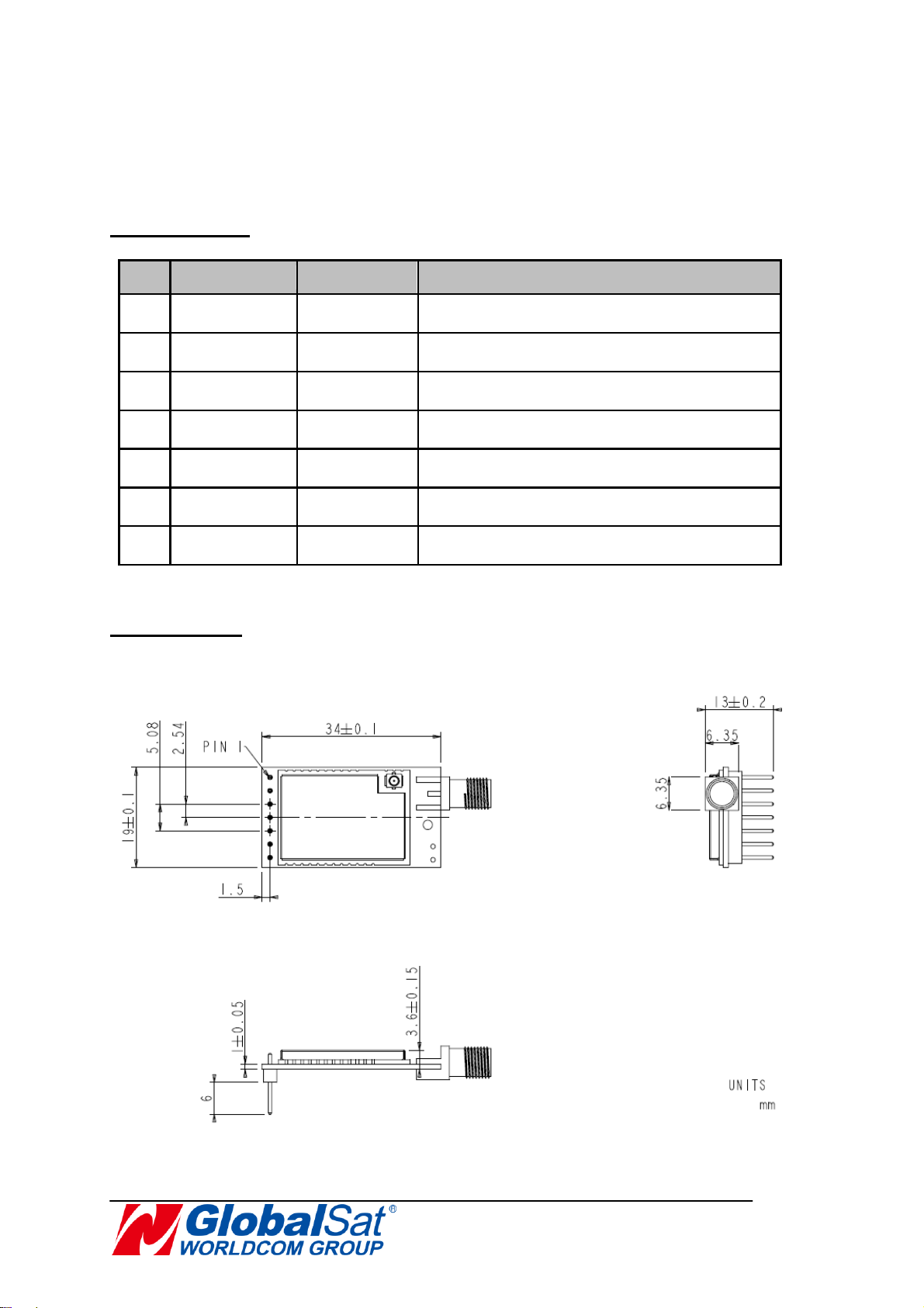
Dimension
34 x 19 ± 0.1 mm (PCBA)
Connector
PIN type, pitch 2.54mm
Accessories
RPSMA Antenna (Optional)
Gain:
2.95 dBi @ 902 MHz;
2.88 dBi @ 915 MHz;
2.89 dBi @ 928 MHz
USB to UART Adapter Board (Optional)
Hardware Specifications
No
Pin
Definition
Description
1
GND
GND
Ground
2
VCC
Input
3.0 ~ 6.0 V
3
RXD
Input
UART input
4
TXD
Output
UART output
5
BZ
Output
Module’s operation status
6
P2
Input
Pin2 for switching operation mode
7
P1
Input
Pin1 for switching operation mode
Pin Definition
Product Size

LoRaWAN™ Configuration
Activation of an end-device can be achieved in two ways, either via Over-The-Air
Activation (OTAA) when an end-device is deployed or reset, or via Activation By
Personalization (ABP) in which the two steps of end-device personalization and activation
are done as one step.
Over-the-Air Activation
For over-the-air activation, end-devices must follow a join procedure prior to
participating in data exchanges with the network server. An end-device has to go
through a new join procedure every time it has lost the session context information. The
join procedure requires the end-device to be personalized with the following information
before its starts the join procedure: a globally unique end-device identifier (DevEUI), the
application identifier (AppEUI), and an AES-128 key (AppKey).
Activation by Personalization
Under certain circumstances, end-devices can be activated by personalization.
Activation by personalization directly ties an end-device to a specific network by-passing
the join request join accept procedure.
Activating an end-device by personalization means that the DevAddr and the two
session keys NwkSKey and AppSKey are directly stored into the end-device instead of
the DevEUI, AppEUI and AppKey. The end-device is equipped with the required
information for participating in a specific LoRa network when started. Each device should
have a unique set of NwkSKey and AppSKey. Compromising the keys of one device
shouldn‘t compromise the security of the communications of other devices.
Operation Mode
Bi-directional end-devices (Class A): End-devices of Class A allow for bi-directional
communications whereby each end-device's uplink transmission is followed by two
short downlink receive windows. The transmission slot scheduled by the end-device
is based on its own communication needs with a small variation based on a random
time basis (ALOHA-type of protocol). This Class A operation is the lowest power
end-device system for applications that only require downlink

communication from the server shortly after the end-device has sent an uplink
Save Settings
Command
Description
AAT1 Save
Respond ok after parameters are saved.
Reset and Reboot CPU of LM-130H1
Command
Description
AAT1 Reset
Respond ok after entering the command.
Restore to Firmware Default Value
Command
Description
AAT1 Restore
Respond ok after entering the command.
Enable / Disable MOST Link mode
Command
Description
AAT3 P0=[parameter]
[Parameter]:1/0
1: enable MOST-Link
0: disable MOST-Link
Response:
ok ﹣parameter is valid
invalid_param ﹣parameter is not valid
transmission. Downlink communications from the server at any other time will have
to wait until the next scheduled uplink.
Bi-directional end-devices with maximal receive slots (Class C): End-devices of
Class C have nearly continuously open receive windows, only closed when
transmitting.
MOST-Link Configuration
Please refer to below AT Command List for the detail setting.
AAT1 - Command for parameters setting up and send /receive data.
AAT3 - Command for functions setting up under MOST-Link.
Under this protocol, the default mode is Disable (P0=0), which is the payload data
transmission in transparent. It only supports command A0, A1 for AES128 encryption
function.
Use AT command [AAT3 P0=1] to Enable MOST-Link mode.

Read MOST-Link mode status
Command
Description
AAT3 P0=?
Response:
1-MOST-Link is enabled
0-MOST-Link is disabled
Set Operation Mode of LM-130H1
Command
Description
AAT3 MD=[parameter]
[parameter]: Range: 1-3, Default=1
1: Mode 1, Normal mode
2: Mode 2, Wake up mode
3: Mode 3, Power saving mode
Response:
ok ﹣parameter is valid
invalid_param ﹣parameter is not valid
Note:
1.
In Wake up mode, LM-130H1 stays
awake and send wake up code (i.e.
Normal mode plus with preamble byte)
while transmitting data.
2.
In Power-saving mode, LM-130H1 sleeps
all the time. Send [AAT1 WK] or any
command would get “ACK” as a wake up
code. After getting “ACK” within 0.5
second, send [AAT3 MD=1] to change it to
Normal Mode. LM-130H1 would only
accept commands [AAT3 MD] and [AAT1
Save] in power-saving mode.
Read Operation Mode of LM-130H1
Command
Description
AAT3 MD=?
Response:
1
﹣Normal mode
2
﹣Wake up mode
3
﹣Power saving mode

Read LoRa® MAC of LM-130H1
Command
Description
AAT1 L0=?
Response: LoRa® MAC of LM-130H1
(16 Bytes)
Example, 9B667C111B001B80
Read Model Name
Command
Description
AAT1 L1=?
Response: Model name (7 Bytes)
Example, LM-130H1/LM-533
Read LoRa® Firmware Version
Command
Description
AAT1 L2=?
Response: Firmware version (16 Bytes)
Example, F-0LR-14-1704191
Set LoRa Group ID
Command
Description
AAT1 L3=[parameter]
[Parameter]: The number of LoRa® group ID.
The range is 0~255. 0=disable group ID
function.
Default=0
Response:
ok ﹣parameter is valid
invalid_param ﹣parameter is not valid
Read LoRa® Group ID
Command
Description
AAT1 L3=?
Response: The group ID (Range:0~255)

Set Rx/Tx Frequency of LoRa® Channel
Command
Description
AAT1
L4=[parameter1],[parameter2]
[Parameter1]: Rx frequency in KHz from
865000 to 928000
[Parameter2]: Tx frequency in KHz from
865000 to 928000
Response:
ok ﹣parameters are valid
invalid_param ﹣one or both parameter are
not valid
Example, set Rx frequency as 915MHz and Tx
frequency as 915MHz
The command is AAT1 L4=915000,915000
Read Rx/Tx Frequency of LoRa® Channel
Command
Description
AAT1 L4=?
Response: Rx frequency in KHz, Tx frequency
in KHz
Set Data Rate of LoRa® Channel
Command
Description
AAT1 L5=[parameter]
[Parameter]: Data rate from 0 to 5
0=0.81K, 1=1.46K, 2=2.6K, 3=4.56K, 4=9.11K,
5=18.23K bps
Default=3
Response:
ok ﹣parameter is valid
invalid_param ﹣parameter is not valid
Read Data Rate of LoRa® Channel
Command
Description
AAT1 L5=?
Response: Data Rate from 0 to 5

Set Wakeup Time of LoRa® Channel
Command
Description
AAT1 L6=[parameter]
[Parameter]: Wakeup time from 0 to 9 0=200ms,
1=400ms, 2=600ms, 3=1s, 4=1.5s, 5=2s,
6=2.5s, 7=3s, 8=4s, 9=5s
Default=3
Response:
ok ﹣parameter is valid
invalid_param ﹣parameter is not valid
Read Wakeup Time of LoRa® Channel
Command
Description
AAT1 L6=?
Response: Wakeup time from 0 to 9
Set the index of LoRa® Channel’s Tx Power
Command
Description
AAT1 L7=[parameter]
[Parameter]: Index of Tx power from 0 to 7
0=5dBm, 1=7dBm, 2=9dBm, 3=11dBm,
4=13dBm, 5=15dBm, 6=17dBm, 7=20dBm
Default=7
Response:
ok
﹣
parameter is valid
invalid_param ﹣parameter is not valid
Read the index of LoRa® Channel’s Tx Power
Command
Description
AAT1 L7=?
Response: Index of Tx power from 0 to 7
Set LM-130H1’s Role
Command
Description
AAT1 MA=[parameter]
[Parameter]: 1/0
0: set LM-130H1 as Node
1: set LM-130H1 as Gateway
Default=0
Response:
ok
﹣
parameter is valid
invalid_param ﹣parameter is not valid
Read LM-130H1’s Role Status

Command
Description
AAT1 MA=?
Response:
0﹣Node
1﹣Gateway
Send Payload by M.O.S.T. protocol
Command
Description
AAT1 T1=[parameter]
* MOST-Link disable, P0=0
[Parameter]: Payload value in
hexadecimal character (1-99 Bytes).
Response: This command would get two
responses. The first one responding if the
command is valid or not. After the payload is
sent out, it would get the second response.
1st Response:
ok ﹣parameter is valid
invalid_param ﹣parameter is not valid
2nd Response:
TX_OK﹣payload is sent out
TX_BUSY﹣payload is not sent out
Received Data from End
Node AAT1 R1=RSSI,Data
RSSI: The received signal strength
indicator
(Range: 1~160). The bigger the value is, the
stronger the signal strength is.
Data:
in hexadecimal character (1-99
Bytes). It is
ended with <CR><LF>

Send Payload by MOST-Link protocol (LM-130H1 is gateway, MA=1)
Command
Description
AAT1
T2=[parameter1],[parameter2],[para
maeter3]
* MOST-Link enable, P0=1
[Parameter1]:1/0
1: ACK enable
0: ACK disable
[Parameter2]:LoRa®_MAC
The LoRa® MAC that assigned to get the payload
[Parameter3]:payload
Payload value in hexadecimal character (1-84
Bytes).
Response: This command would get two responses.
The first one responding if the command is valid or
not. After the payload is sent out, it would get the
second response.
1st Response:
ok ﹣parameters are valid
invalid_param ﹣parameter is not valid
2nd Response:
TX_OK﹣payload is sent out
TX_NO_ACK﹣payload is sent out, but not get
ACK
TX_BUSY﹣payload is not sent out
Received Data from End Node
AAT1 R2=RSSI,0,flag,data
RSSI: The received signal strength indicator
(Range:
1~160). The bigger the value is, the stronger the
signal strength is.
flag: MOST-Link AT Command Flag (1 Byte
in
hexadecimal value)
Data: in hexadecimal character (1-84 Bytes).
It is
ended with <CR><LF>

Send Payload by MOST-Link protocol
(LM-130H1 is end node, MA=0)
Command
Description
AAT1 T3=[parameter1],[parameter2]
* MOST-Link enable, P0=1
[Parameter1]:1/0
1: ACK enable
0: ACK disable
[Parameter2]:payload
Payload value in hexadecimal character (1-84
Bytes).
Response: This command would get two responses.
The first one responding if the command is valid or
not. After the payload is sent out, it would get the
second response.
1st Response:
ok ﹣parameters are valid
invalid_param ﹣parameter is not valid
2nd Response:
TX_OK﹣payload is sent out
TX_NO_ACK﹣payload is sent out, but not get
ACK
TX_BUSY﹣payload is not sent out
Received Data from Gateway
AAT1 R2=RSSI,LoRa_MAC,flag,data
RSSI: The received signal strength indicator
(Range:
1~160). The bigger the value is, the stronger the
signal strength is.
LoRa_MAC: The LoRa® MAC of end node
that
sends payload to gateway (16 Bytes)
flag: MOST-Link AT Command Flag (1 Byte
in
hexadecimal value)
Data: in hexadecimal character (1-84 Bytes).
It is
ended with <CR><LF>

Enable/ disable AES128 Encryption
Command
Description
AAT3 A0=[parameter]
[Parameter]:1/0
1: Enable AES128 Encryption
0: Disable AES128 Encryption
Response:
ok ﹣parameter is valid
invalid_param ﹣parameter is not valid
Read AES128 Encryption Status
Command
Description
AAT3 A0=?
Response
1- Enable AES128 Encryption
0- Disable AES128 Encryption
Set AES128 Encryption
Command
Description
AAT3 A1=[parameter]
[Parameter]: AES128 Key in hexadecimal
character(16 Bytes)
Response:
ok ﹣parameter is valid
invalid_param ﹣parameter is not valid
Default=476C6F62616C53617432303136616263
Read AES128 Encryption
Command
Description
AAT3 A1=?
Response: AES128 Key in hexadecimal
Character
15

Set Retries Number and Timeout of MOST-Link
Command
Description
AAT3 P3=[parameter1],[parameter2]
[Parameter1]: Retries number of MOST-Link while
not getting ACK (0~9) 0=disable, Default=0
[Parameter2]: Timeout of getting ACK (1~255
seconds) Default=3
Response:
ok ﹣parameter are valid
invalid_param ﹣one or both parameter are not
valid
Read Retries Number and Timeout of MOST-Link
Command
Description
AAT3 P3=?
Response: Retries number,timeout
16

Federal Communication Commission Interference Statement
This device complies with Part 15 of the FCC Rules. Operation is subject to the
following two conditions: (1) This device may not cause harmful interference, and (2)
this device must accept any interference received, including interference that may
cause undesired operation.
This equipment has been tested and found to comply with the limits for a Class B
digital device, pursuant to Part 15 of the FCC Rules. These limits are designed to
provide reasonable protection against harmful interference in a residential installation.
This equipment generates, uses and can radiate radio frequency energy and, if not
installed and used in accordance with the instructions, may cause harmful interference
to radio communications. However, there is no guarantee that interference will not
occur in a particular installation. If this equipment does cause harmful interference to
radio or television reception, which can be determined by turning the equipment off
and on, the user is encouraged to try to correct the interference by one of the following
measures:
Reorient or relocate the receiving antenna.
Increase the separation between the equipment and receiver.
Connect the equipment into an outlet on a circuit different from that
to which the receiver is connected.
Consult the dealer or an experienced radio/TV technician for help.
FCC Caution:
Any changes or modifications not expressly approved by the party responsible for
compliance could void the user's authority to operate this equipment.
This transmitter must not be co-located or operating in conjunction with any other
antenna or transmitter.
FOR MOBILE DEVICE USAGE (>20cm/low power)
Radiation Exposure Statement:
This equipment complies with FCC radiation exposure limits set forth for an
uncontrolled environment. This equipment should be installed and operated with
minimum distance 20cm between the radiator & your body.
17

This device is intended only for OEM integrators under the following conditions:
1) The antenna must be installed such that 20 cm is maintained between the antenna
and users, and
2) The transmitter module may not be co-located with any other transmitter or
antenna.
As long as 2 conditions above are met, further transmitter test will not be required.
However, the OEM integrator is still responsible for testing their end-product for any
additional compliance requirements required with this module installed
IMPORTANT NOTE: In the event that these conditions can not be met (for example
certain laptop configurations or co-location with another transmitter), then the FCC
authorization is no longer considered valid and the FCC ID can not be used on the
final product. In these circumstances, the OEM integrator will be responsible for
re-evaluating the end product (including the transmitter) and obtaining a separate FCC
authorization.
End Product Labeling
This transmitter module is authorized only for use in device where the antenna may be
installed such that 20 cm may be maintained between the antenna and users. The
final end product must be labeled in a visible area with the following: “Contains FCC
ID:RID-LM110H1”. The grantee's FCC ID can be used only when all FCC compliance
requirements are met.
Manual Information To the End User
The OEM integrator has to be aware not to provide information to the end user
regarding how to install or remove this RF module in the user’s manual of the end
product which integrates this module.
The end user manual shall include all required regulatory information/warning as show
in this manual.
The document is subject to change without notice. Copyright © 2018, GlobalSat WorldCom Group
18
 Loading...