

Page 1

TR-151A
Vehicle/Asset Tracker
User Manual
Version 0.9.9
Page 2

Table of Content
1. Introduction and Features..............................................................................................3
1.1 Introduction............................................................................................................3
1.2 Features.................................................................................................................3
1.3 Hardware................................................................................................................4
2. Start-up.......................................................................................................................... 5
2.1 Accessories.............................................................................................................5
2.2 Install SIM card and Battery...................................................................................... 6
2.3 Charging the battery ................................................................................................9
2.4 TR-151A with magnetic holder .................................................................................10
2.5 Turn on/off the device.............................................................................................12
2.6 Button Description .................................................................................................12
2.7 DIP switch ............................................................................................................15
3. TR-151A Setup and Call Center Operation .................................................................... 16
3.1 Install the USB driver .............................................................................................16
3.2 Install the Call Center program ................................................................................17
3.3 Call Center Operation .............................................................................................18
3.3.1 Set TR-151A by call center for the first time. ....................................................18
3.3.2 View the IMEI code and phone number of TR-151A device..................................20
3.3.3 Delete a user (TR-151A device) from Call center ...............................................21
3.4 Description of the Call Center UI ..............................................................................22
3.5 SMS Tracking commands and Configuration for SMS Call Center software developer ........26
4. Operating the TR-151A.................................................................................................27
4.1 How to set SOS number of TR-151A?........................................................................27
4.2 How to set TR-151A to immediately report its position by SMS?....................................28
4.3 How to set TR-151A to periodically report its position by SMS?.....................................29
4.4 How to set TR-151A to immediately report its position by GPRS? ..................................30
4.5 How to set TR-151A to periodically report its position by GPRS?....................................31
4.6 Tracking/Monitoring TR-151A by GPRS ......................................................................32
4.7 Displaying the location on map ................................................................................33
4.8 How to set TR-151A enter Geofence mode? ............................................................... 35
4.9 How to make TR-151A do Voice monitor function? ......................................................38
4.10. How to set TR-151A enter Parking Mode?................................................................39
4.11 How to set TR-151A enter Sleeping Mode?...............................................................40
4.12 The return format from TR-151A ............................................................................ 41
4.13 SMS Configuration................................................................................................43
4.13.1 SMS Configuration _ SMS Default Return Phone Number...................................45
4.13.2 SMS Configuration _ Maximum GPS Fixing Time..............................................46
4.13.3 SMS Configuration _ Default Report Mode Setting............................................ 47
4.13.4 SMS Configuration _ GPRS Setting ................................................................48
TR-151A page 2
Page 3

1. Introduction and Features
1.1 Introduction
TR-151A is a durable and water resistant GPS/GSM/GPRS tracker. Users can install TR-151A
on vehicles or assets for tracking. It can send out SMS with its location (longitude and latitude) to
user’s cell phone by GSM network or to personal computer by internet connection of GPRS
network. Then users can track the location of their vehicles or assets. TR-151A is designed to
equip with high capacity of Li-ion battery for long operation time. There is one SOS button on the
TR-151A for emergency help. It is very easy to install or hide TR-151A in the car to perform
tracking. TR-151A is ideal application for vehicle tracking and equipment/assets monitoring.
1.2 Features
z High sensitive GPS chipset
z Combination of GPS ,GSM/GPRS wireless network
z Durable and water resistant GPS tracker
z Easy to install or hide in the car to perform tracking. No external wires needed.
z Ideal application for vehicle tracking and equipment/assets monitoring
z Optional external antenna for GPS reception
z Rechargeable 2100mA high capacity Li-ion battery for long operation time
z External DC power supply
z Configuration can be done via SMS commands or by application software via USB interface.
z SOS (emergency) button.
z Voice monitor function to monitor the sound/conversation live.
z Geofence function
NOTE: Voice Monitoring function allows user to send a SMS with voice monitoring command by a cellular phone
to TR-151A. TR-151A will call back to the returned number in the SMS. And then user can listen to the sound or
voice around TR-151A. While users listen to the sounds or voice around TR-151A, people who around TR-151A
won’t know they are under voice monitoring. Please refer to page29 to get the detailed method of making voice
monitoring.
NOTE: Geofence feature allows user to set up to 10 permissible or restricted areas whose shape is either circular
or rectangular for tracking the vehicles or monitoring the equipment/assets. Users can choose to receive alarm
message if TR-151A enters the restricted areas or to receive alarm message if TR-151A gets out the permissible
areas. Please refer to page 26-28 to get the detailed setting method of Geofence.
TR-151A page 3
Page 4

1.3 Hardware
Frequency range(Uplink): Min Typ Max Unit
Frequency range(Downlink): Min Typ Max Unit
GSM module: TR-151A: Siemens GSM 850/1800/1900
GSM850: 824 849 MHz
GSM1800: 1710 1785 MHz
GSM1900: 1850 1910 MHz
GSM850: 869 894 MHz
GSM1800: 1805 1880 MHz
GSM1900: 1930 1990 MHz
RF power: Min Typ Max Unit
GSM850: 31 33 35
GSM1800: 28 30 32
GSM1900: 28 30 32
GSM Class Small MS
GPRS connectivity
GPS Chipset:
Frequency: L1, 1575.42 MHz
C/A code: 1.023 MHz chip rate
Channels: 32 channel all-in-view tracking
Horizontal Position Accuracy: 10 meters, 2D RMS
Hot start: 1 sec., average
Warm start: 38 sec., average
Cold start: 42 sec., average
Altitude Limit: 18,000 meters (60,000 feet) max.
Velocity Limit: 515 meters/second (1000 knots) max.
Acceleration Limit: Less than 4g
Jerk Limit: 20 m/sec3
Operating temperature: -20° to 55° C
‧ GPRS multi-slot class 10
‧ GPRS mobile station class B
MT3318
Antenna Type: GPS patch antenna
Dimension: 86.7*48.9*32.5 mm
Battery: 2100mA rechargeable Li-ion battery
LED indicator: For Charging, GPS, GSM and Status.
Interface: Mini USB port for connecting to PC
Casing: Water resistant (IPX4)
GPS external antenna port: MMCX port
TR-151A page 4
Page 5

2. Start-up
2.1 Accessories
TR-151A
USB Cable
Belt Clip (optional)
AC charger
Battery
TR-151A page 5
Page 6

2.2 Install SIM card and Battery
z Use a coin or screwdriver to loosen the screw on back cover.
z Lift up the back cover and remove it as the direction shown.
TR-151A page 6
Page 7

z Push forward the cover of SIM card slot to the position marked with “OPEN”. Then lift up
the cover.
z Insert the SIM card with its metal contacts facing down and the cut corner at the top left.
Note: It is suggested to disable the SIM PIN protection function (asks SIM PIN entry while turn
on the device) by your cellular phone before installing the SIM card in TR-151A
z Plug the battery connector into socket. Be aware that the red wire must be plugged on the
top side.
TR-151A page 7
Page 8

z Please put the connector wire under the battery, and then put the battery into battery
compartment.
NOTE: After installing the battery, the status LED will emit red light. After the LED go out, please
wait for 5 seconds before turning on the power.
NOTE: Please take out the battery if you do not use TR-151A for a long time.
TR-151A page 8
Page 9

2.3 Charging the battery
Before using TR-151A for the first time, please fully charge it by connecting to AC power adapter
under the power-off condition. (The attached battery is specially designed for TR-151A. Please
do not use other type of battery; otherwise it will damage the device. If you need to change the
battery of TR-151A, please contact your local dealer.) You can also charge the TR-151A by
connect it to PC or Notebook via USB cable. (The power of PC or of notebook should be turned
on.)
TR-151A page 9
Page 10

2.4 TR-151A with Belt Clip
z Insert the TR-151A with the Power button side facing out.
z Push TR-151A into the Belt Clip until it clicks in position.
TR-151A page 10
Page 11
z There are 4 circular magnets on back of the Belt Clip for attaching TR-151A onto the
metal material of vehicle or machine.
z To remove TR-151A, slightly push outward the two sides of holder, and slide out the
TR-151A.
TR-151A page 11
Page 12

2.5 Turn on/off the device
● Turn on: After installing the battery, the status LED will emit red light. After the LED go out,
please wait for 5 seconds before turning on the power. Press the power button for 3~4
seconds. When the device is turned on, GPS will do cold start to get fixed its position for
the first time with the green GPS LED on. If location is fixed, the LED will blink. It is
suggested that you stay at outdoor places or near the window where TR-151A can receive
the better GPS signal when you turn on the device.
NOTICE: If it does not successfully get the location fixed after turning the power on,
TR-151A may be located in the weak signal area or on the move.
● Turn off: Press the Power button for 3~4 seconds. When the power is turned off, LED will
go out.
2.6 Button Description
TR-151A page 12
Page 13

Power button
SOS button
Indicator
1. Power On: Press and hold the power button for 3-4 seconds. The
status LED will flash 2 times
2. Power Off: Press and hold the power button for 3-4 seconds. The
status LED will flash 1 time.
3. Enter parking mode: Press the power button once to enter parking
mode. When power button is pressed, LED will flash slowly (once
per second) first, and then enter parking mode. The flash number is
the second number you set in Park_Time.
Press the SOS Button, the status LED will flash 3 times to indicate the
button is activated. TR-151A will immediately send out emergency
messages along with its GPS report to 3 preset phone numbers.
1. GSM LED:
y Voice monitoring: LED keeps on.
y When no SIM card is inserted, network searches in progress,
ongoing user authentication, or network login in progress: LED
blinks quickly (about once per second).
y In standby mode: LED blinks slowly (once for 3 seconds)
2. GPS LED: The LED keeps on when it is fixing the location. The LED
blinks when TR-151A’s location has been fixed. When GPS function
is disabled, GPS LED will be off.
3. Status LED:
y When battery low: LED keeps on.
y When enter setup mode: LED keeps on.
y Press power button to turn on: LED flashes quickly 2 times.
y Press power button to turn off: LED flashes quickly 1 time.
y When SOS button is pressed: LED flashes slowly 3 times.
y When error occurs: LED flashes quickly 5 times.
y Parking mode: When power button is pressed, LED will flash
slowly (once per second) first, and then enter parking mode. The
flash number is the second number you set in Park_Time. If you
want to stop parking mode, press the power button again. The LED
flashes quickly 3 times and it will exit parking mode.
y Sleeping mode: LED will flash slowly 60 times and then it enters
sleeping mode.
4. Power LED:
y The LED emits orange light when charger is plugged for charging
the battery.
y The LED goes off after the battery has been fully charged.
TR-151A page 13
Page 14

USB connector
There are two functions of the USB connector:
1. Connect TR-151A to PC by a Mini USB cable and setup all its
features and functions from application software through PC.
2. Charge the battery by connecting a USB cable.
Microphone For voice monitoring use.
External antenna
For you to connect a MMCX external GPS antenna.
connector
TR-151A page 14
Page 15
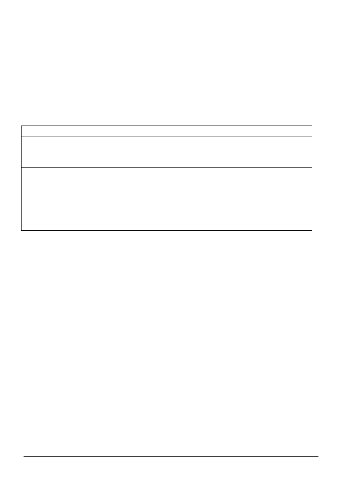
2.7 DIP switch
On Off
Switch 1
Switch 2
Switch 3
Switch 4
Note: You can set the switch by a little tweezers or pen point or toothpick.
Enable TR-151A to automatically
power on when it is connected to
external power.
All LED works as user mode. Make all LED except status LED go off
Setting Mode (Status LED keeps
emitting red light)
Sleeping Mode User Mode
Users have to press the power button
to power on TR-151A whether
external power is connected or not.
for secret tracking. Status LED works
as user mode.
User Mode
TR-151A page 15
Page 16

3. TR-151A Setup and Call Center
Operation
3.1 Install the USB driver
1.) Insert the Driver CD into your CD-ROM driver.
2.) AutoRun installation window will appear.
3.) Click “Install USB Driver” button to install the USB driver.
4.) You will see two folders. If your Windows is Vista version, please double click to open
“PL2303_USB_Driver_for_Windows_Vista” folder and double click on “PL-2303 Vista
Driver Installer.exe” to begin installation. Follow the instruction to complete the installation
process.
5.) If your Windows is XP or 2000 version, please double click to open
“PL2303_USB_Driver_for_Windows_2000_XP” folder and double click on “PL-2303
Driver Installer.exe” to begin installation. Follow the instruction to complete the installation
process.
TR-151A page 16
Page 17

3.2 Install the Call Center program
1.) Click “Install PC Software” button to install the Call Center program.
2.) Follow the instruction to complete the installation process.
3.) After the installation is completed, you will see the icon “TR151-Call Center” appears on
desktop. Double click on this icon to start TR151 Call Center program.
TR-151 Call
Center
TR-151A page 17
Page 18

3.3 Call Center Operation
3.3.1 Set TR-151A by call center for the first time.
1. Make TR-151A enter setting mode by setting DIP switch 3 to the “ON” position.
2. Connect TR-151A and PC by the USB cable.
3. Turn on the power of TR-151A. (The status LED will emit red light showing it is under setting
mode.)
4. Start call center.
5. Click DeviceÆ TR151 Setup. Or click . Then the window below will be brought up.
TR-151A page 18
Page 19

6. If you do not know TR-151A which COM port is connected to, please click “Scan COM Port”
button to automatically scan it. Then click “Setup” button to enter setup window.
7. Then the window below will be brought up.
8. Write down the IMEI code.
9. Enter a name for TR-151A device in the field of User Name. Enter the phone number of SIM
card installed in TR-151A in the field of Phone Number. Enter the three phone numbers of
emergency help in the field of SOS Number 1~SOS Number3. (ESSENTIAL)
10. Check “SMS Default Return Phone Number” and enter a phone number for receiving
confirmed message or data report. (OPTIONAL)
11. Select the time for GPS fixing in the pull-down menu of Maximum GPS Fixing Time. The
unit is minute. If GPS fixing is not achieved within time, it will close GPS and send back the
previous location info. (OPTIONAL)
12. Select a report mode (Stop Report, Immediate Report, and Period Report) for Default
Report Mode and enter the concerning parameters. (OPTIONAL)
13. Park Mode Setting: Set the time length between entering Parking Mode after pressing the
power button under power on condition in the field of Park Time. Set the interval of sending
Park mode reporting SMS in the field of Park Interval. Set how many Park mode reporting
SMS will be sent in the field of Park Number of Reports. Enter the phone number for
receiving Park mode reporting SMS in the field of Park Return Phone Number.
14. Sleep Moe Setting: Set the time length of Sleep mode in the field of Sleep Time. Set the
TR-151A page 19
Page 20

interval of sending Sleep mode reporting SMS in the field of Sleep Interval. Set how many
Park mode reporting SMS will be sent in the field of Sleep Number of Reports. Enter the
phone number for receiving Park mode reporting SMS in the field of Sleep Return Phone
Number.
15. GPRS Setting: Set the GPRS concerning parameters. For the GPRS setting, please consult
with your GPRS network service provider. (NOTE: GPRS Server Host Name must be a
physical IP of the installed TR-151A call center’s PC)
16. Click OK to save the setting and then unplug the USB cable from PC and TR-151A.
17. Press power button to turn off TR-151A.
18. Remember to make TR-151A exit from setting mode by setting DIP Switch 3 to “OFF”
position.
3.3.2 View the IMEI code and phone number of TR-151A device
Users can view the IMEI code and phone number of TR-151A that has been made basic setup
by management center.
Click Management Æ User Information. Or click . Then the window below will be
brought up.
TR-151A page 20
Page 21
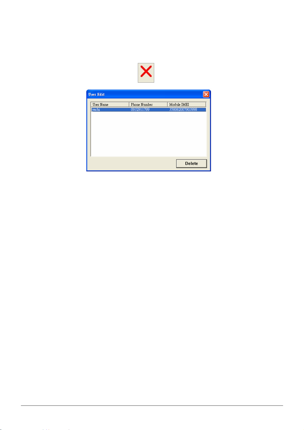
3.3.3 Delete a user (TR-151A device) from Call center
Management center can only store five sets of TR-151A’s information. If user would like to add
the 6th set of TR-151A, please delete one set of the existing TR-151A.
Click Management Æ User Edit. Or click . Then the window below will be brought up.
Highlight the TR-151A you’d like to delete, and then click Delete button.
TR-151A page 21
Page 22
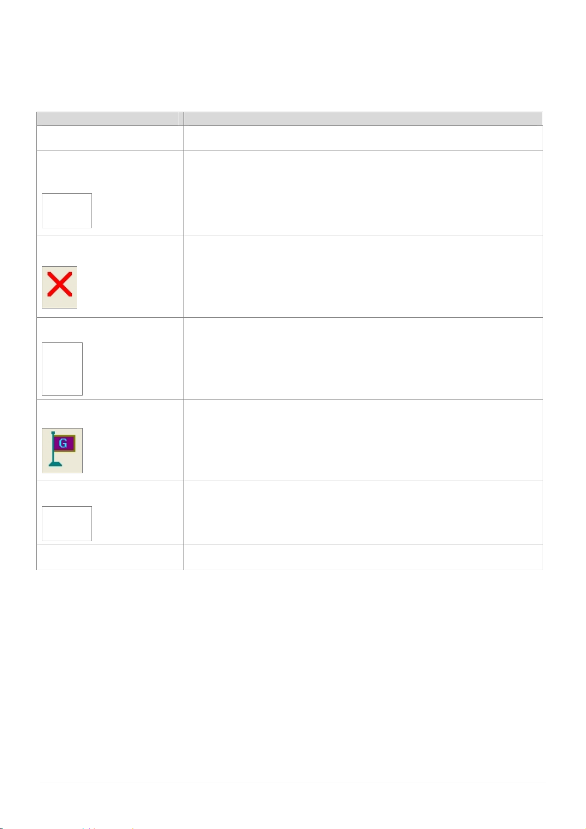
3.4 Description of the Call Center UI
Menu item Description
File > Exit Close the Call Center program.
Management > User
Information
Management > User Edit
Device > TR151 Setup
Map > View Tracking Points
Display the User (TR-151A) Information. You can setup up to 5 users in the Call
Center. (Each Call Center can manage up to 5 sets of TR-151A.)
For deleting a user. The Call Center can only hold 5 users’ information at most. If
you want to add a new user after you have already set 5 users, please delete an
existing one.
When a TR-151A is connected to your PC, you can do the basic setup for
TR-151A.
Check this item to mark returned location in the Google Map.
When you receive the latest data report from TR-151A, it will automatically
update the point on Google Map. This function only works under the "SMS
Map > Export KML File
About Version information.
Tracking" mode.
Save the records as the KML format. You can import the KML file to
Google Earth, and it will display the location route. This fun ction only
works under the "Search Records" mode.
TR-151A page 22
Page 23
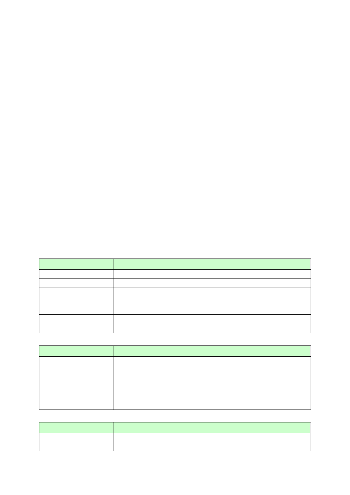
Information: the basic information of TR-151A
Item Description
Firmware Version
Module IMEI
Set Time Zone
User Name
Phone Number
Firmware version of TR-151A
International Mobile Equipment Identity
On: The SMS returned by TR-151A will contain a local time.
Off: The SMS returned by TR-151A will contain a Coordinated Universal
Time, abbreviated UTC.
Enter a user name here.
Enter the phone number of SIM card installed in this TR-151A.
SMS Default Return Phone Number
Item Description
TR-151A will send data report or confirmed message back to this return
phone number that is in the last field of all SMS tracking commands.
SMS Default Return
Phone Number
If user leaves “Return Phone Number” empty in the tracking commands,
TR-151A will send report back to “SMS Default Return Phone Number”.
If “Return Phone Number” and “SMS Default Return Phone Number”
are both empty, TR will send report back to caller ID.
Maximum GPS Tracking Time
Item Description
Maximum GPS Fixing
Time
TR-151A page 23
The time that allows for GPS fixing. If GPS fixing is not achieved in time, it
will close GPS and send back the previous location info.
Page 24
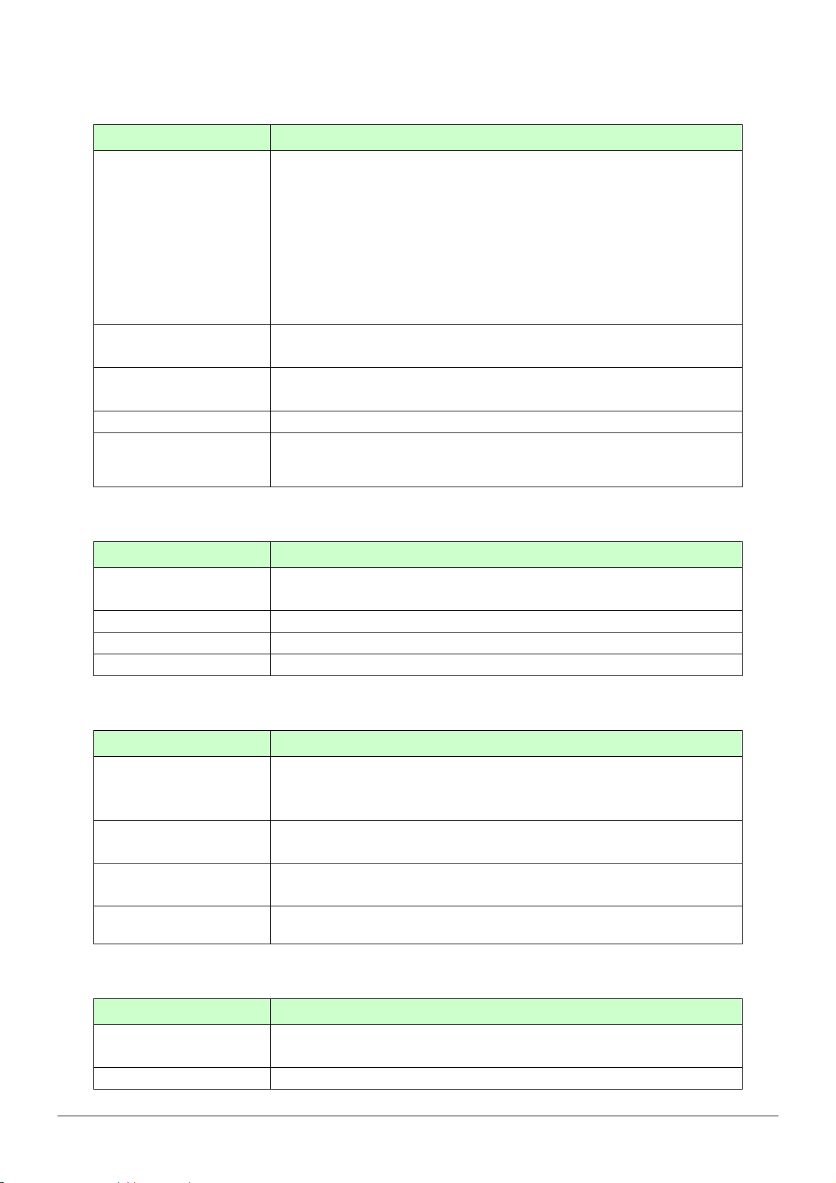
Default Report Mode Setting
Item Description
User can configure TR-151A to perform the “Default Report Mode”.
There are 3 report modes: immediate report, period report, stop report
(standby). When you select some report mode, the unavailable item will be
Default Report Mode
disabled.
After power on the device, TR-151A will perform the “Default Report Mode”
automatically. For example, if the default report mode is set to “Period
Report” mode, every time when user power on the TR-151A, it will send
out period reports by default.
Report Interval
Report Format
Number of Reports
Return Phone Number
for Default Report
Mode
SOS Number
Item Description
SOS Number
OK
Reset Default
Cancel
Park Mode Setting
Item Description
Time interval of sending data report for period report mode.
The unit is second.
Set TR-151A to return message by Format0 or Format1. (Please see
description later in this user manual.)
Set how many reports will be sent for period report mode?
After turn on the TR-151A, it will perform default report mode and send
the data report to this number.
When SOS button is pressed, TR-151A will call these 3 numbers and
send the SMS of location information.
OK to confirm and save.
Reset system to Factory Default.
Cancel the Setup.
The time of entering Parking Mode after pressing the power button under
Park Time
Park Interval
Park Number of
Reports
Park Return Phone
Number
power on condition.
The value is between 1-300 second, and the default is 30 seconds
The interval of sending alarm SMS when TR-151A senses vibration under
parking mode
Set how many alarm SMS will be sent when TR-151A senses vibration
under parking mode
The phone number for receiving Park mode reporting SMS
Sleep Mode Setting
Item Description
Sleep Time
Sleep Interval
TR-151A page 24
The time length of Sleep mode.
The default is 12 hours
The interval of sending alarm SMS when TR-151A senses vibration under
Page 25
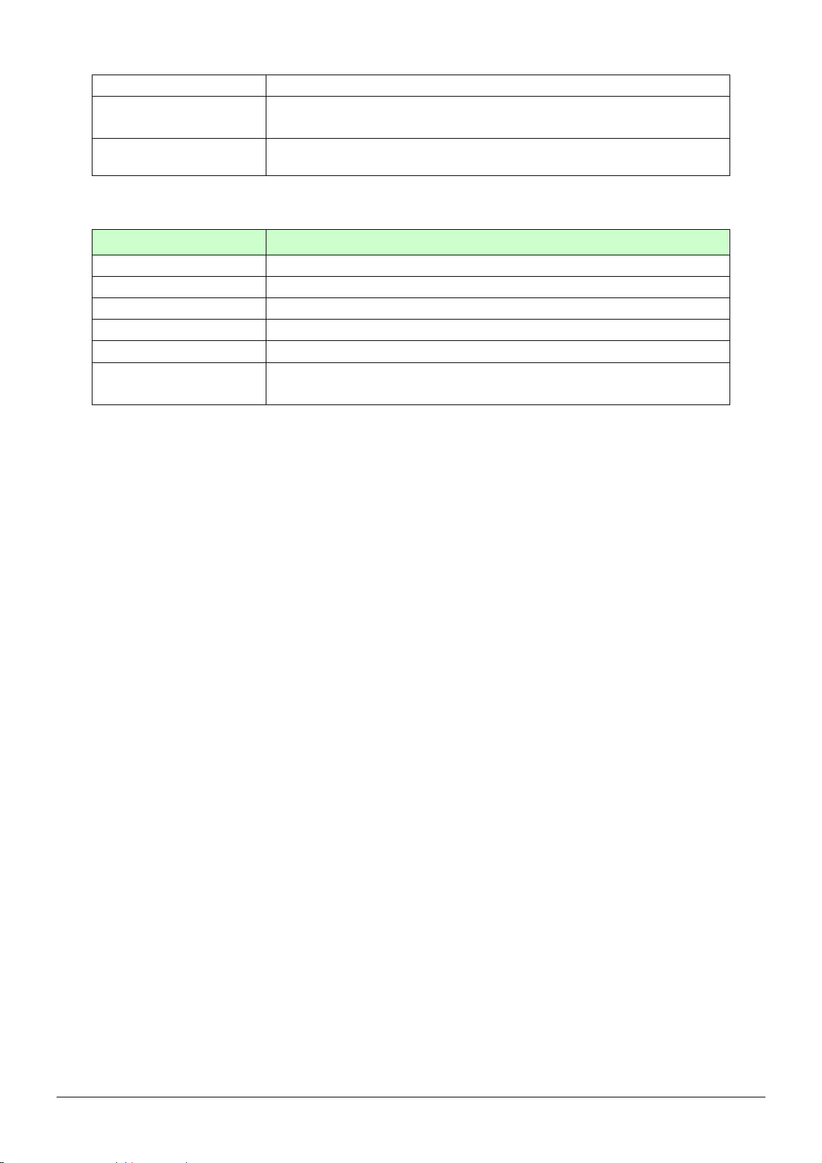
sleep mode
Sleep Number of
Reports
Sleep Return Phone
Number
Set how many alarm SMS will be sent when TR-151A senses vibration
under sleep mode
The phone number for receiving alarm SMS under sleep mode
GPRS Setting
Item Description
GPRS Port
GPRS apn
GPRS user name
GPRS user password
GPRS DNS 1/ DNS 2
GPRS Server Host
Name
The communication port for connecting GPRS network
The APN of GPRS network station
The account for connecting GPRS network
The password for connecting GPRS network
The DNS for connecting GPRS network
GPRS server address (It should be a physical IP of the PC where you
install TR-151A call center)
NOTE: About GPRS setting, please contact with your GPRS network service provider.
TR-151A page 25
Page 26

3.5 SMS Tracking commands and Configuration for SMS
Call Center software developer
You can connect one TR-151A to PC and use GlobalSat PC software Call Center to send SMS
tracking commands and SMS configurations to control the other TR-151A which is outside on
the road. It can help Call Center service providers to evaluate TR-151A and build their own SMS
Call Center efficiently.
Please refer to “SMS_Call_Center_software_Development_manual_VX.X_EN.doc” for details.
TR-151A page 26
Page 27
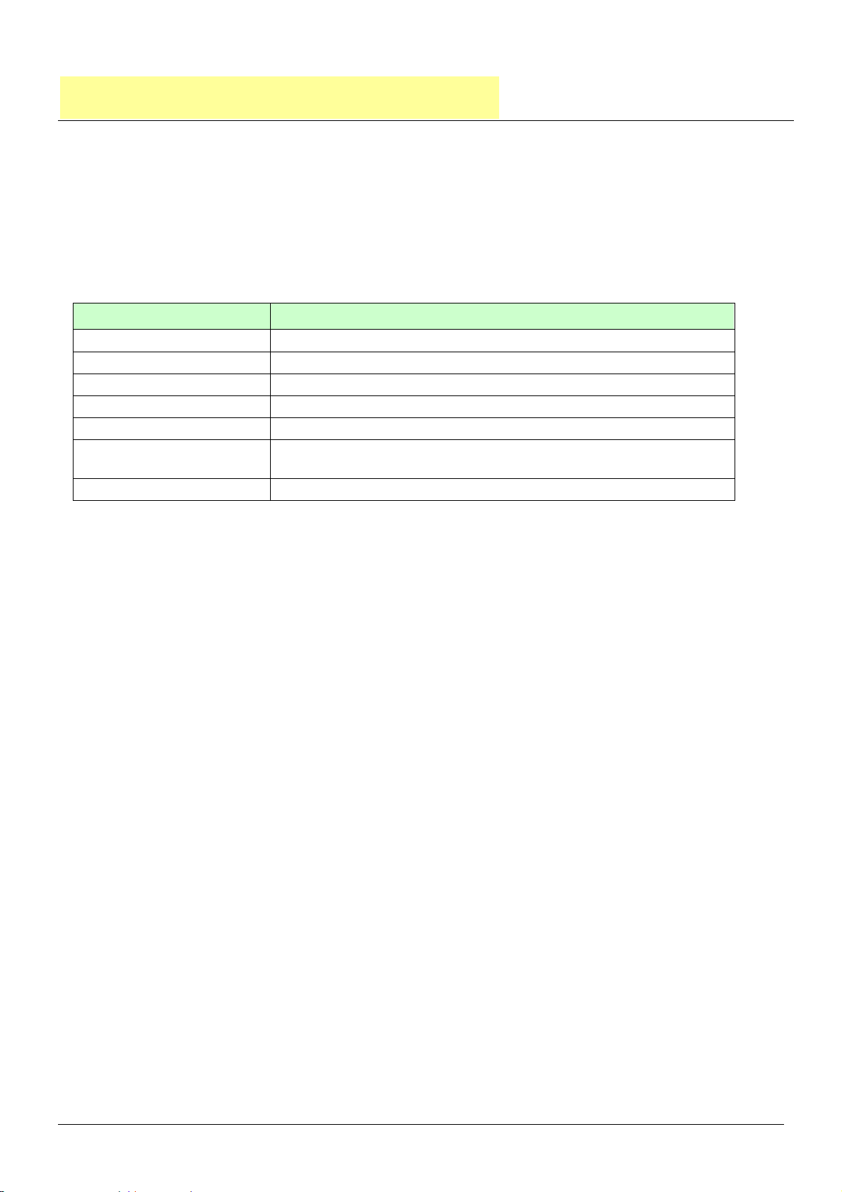
4. Operating the TR-151A
4.1 How to set SOS number of TR-151A?
Users can set SOS number of TR-151A by sending SMS via mobile phone.
The format of SMS is following as:
?7,IMEI,4,SOS1,SOS2,SOS3,Return_Phone_Number!
The table below explains the content of the SMS.
Format Description
? Start sign
7 Function code
IMEI IMEI code of the TR-151A
4 Setting code of SOS number
SOS1, SOS2, SOS3 The phone number for receiving SOS message
Return_Phone_Number
! End sign
The phone number for TR-151A to send an SMS to inform the setting is
OK.
Example 1, if user only wants to set 1 set of SOS, and return phone number as 616123456, you
can send SMS as:
?7,355632000166323,4,616123456,,,626123456!
(You still have to add 2 commas after the set of SOS.)
Example 2, if user wants to set SOS1, SOS2, SOS3, and return phone number as 616123456,
717123456, 818123456, and 626123456, you can send the SMS as.
?7,355632000166323,4,616123456,717123456,818123456,626123456!
NOTE: You can also set SOS number by management center. Please refer to page 18 for the
detail.
TR-151A page 27
Page 28
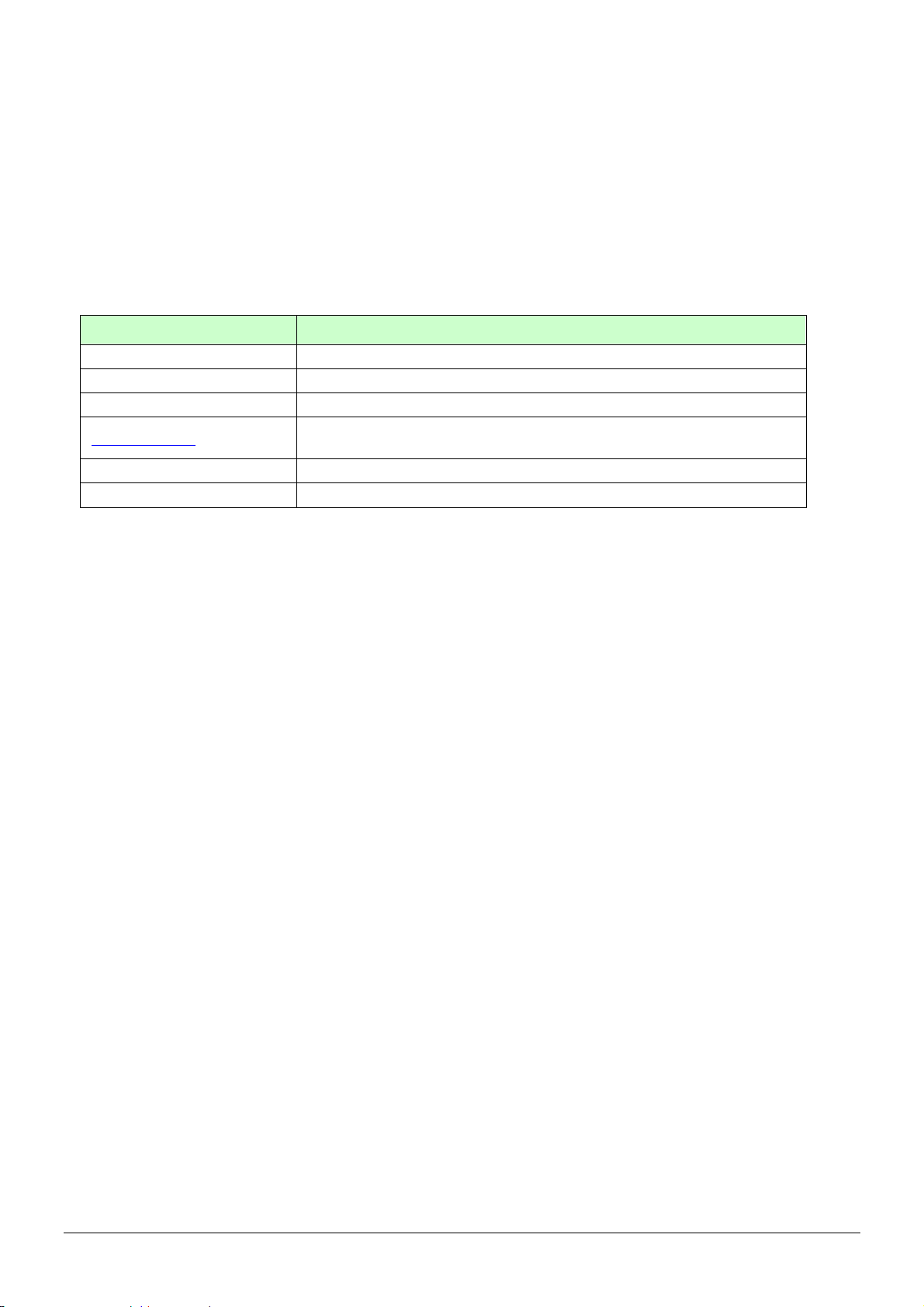
4.2 How to set TR-151A to immediately report its position by
SMS?
Users can send an SMS by mobile phone to ask TR-151A to immediately report its position.
The format of SMS is following as:
?0,IMEI,Report_Format,Return_Phone_Number!
The table below explains the content of the SMS.
Format Description
? Start sign
0 Function code
IMEI IMEI code of the TR-151A
Report_Format
Return_Phone_Number The phone number for receiving the reporting SMS.
! End sign
0 or 1. 0 is for end user, and 1 is for SMS management center
development
TR-151A will send an SMS whose format is “?0,IMEI,OK!” to the return phone number to confirm
it has received the request. And then it will start to get fixed the position. After getting fixed the
position, it will send SMS with its location to the return phone number.
For example: If you’d like to ask TR-151A to send immediate report in format0 to 626-123456.
You have to enter ?0, 355632000166323,0,626123456!
And then you will get ?0,355632000166323,OK!. After TR-151A get fixed of the position, you will
get the position report like
Position report
Name
2008/12/15 10:20:39
N2459.8915,E12129.2186
GPS fixed
NOTE:
If TR-151A can not get fixed the position within the “Maximum GPS Fixing Time”, it will return the
previous location. When the GPS position is fixed, it will again return the position data.
Please refer to page 18 to set “Maximum GPS Fixing Time.”
TR-151A page 28
Page 29
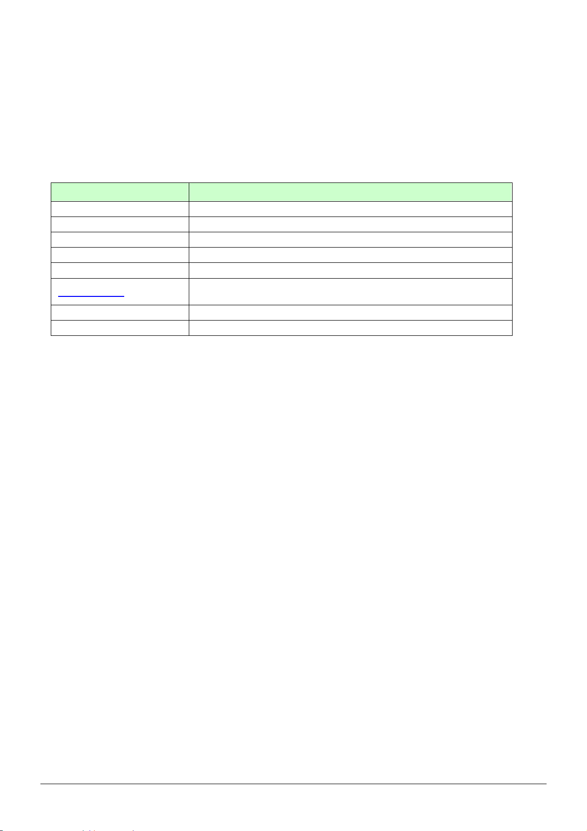
4.3 How to set TR-151A to periodically report its position by
SMS?
Users can send an SMS by mobile phone to ask TR-151A to periodically report its position.
The format of SMS is as below.
?1,IMEI,Report_Interval,Number_of_Reports,Report_Format,Return_Phone_Number!
The table below explains the content of the SMS.
Format Description
? Start sign
1 Function code
IMEI IMEI code of the TR-151A
Report_Interval Set the interval between two reporting SMS
Number_of_Reports Set how many reporting SMS should be sent
Report_Format
Return_Phone_Number The phone number for receiving the reporting SMS.
! End sign
0 or 1. 0 is for end user, and 1 is for SMS management center
development
TR-151A will send an SMS whose format is “?1,IMEI,OK!” to the return phone number to confirm
it has received the request. And then TR-151A will send the SMS with its location to the return
phone number according to the report interval.
NOTE:
If user sets the number of reports as 0, TR-151A will keeps sending the periodical report until
user send the SMS of ?2,IMEI,Return_Phone_Number! to stop the periodical report.
Example 1: Require continuous 120-sec period report in format0 sent to 626123456
You have to enter “? 1,355632000166323,120,0,0,626123456!”
TR-151A will send “? 1,355632000166323,OK!” And then you will get the position report like
Position report
Name
2008/12/15 10:20:39
N2459.8915,E12129.2186
GPS fixed
TR-151A will send position report every 120 seconds until you stop periodical report.
Stop periodical report:
Users can send an SMS to stop periodical report.
The format of SMS is following as?2,IMEI,Return_Phone_Number!
TR-151A page 29
Page 30
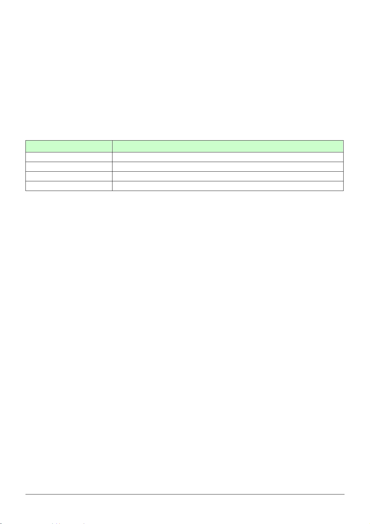
4.4 How to set TR-151A to immediately report its position by
GPRS?
Users can send an SMS by mobile phone to ask TR-151A to immediately report its position via
GPRS network to TR-151A call center or GPRS server.
The format of SMS is following as:
?8,IMEI,Return_Phone_Number!
The table below explains the content of the SMS.
The description of SMS
Format Description
?8 Start sign and function code
IMEI IMEI of TR-151A
Return_Phone_Number The phone number for receiving OK message.
! End sign
TR-151A will send an SMS whose format is “?8,IMEI,OK!” to the return phone number to confirm
it has received the request. And then it will start to get fixed the position. After getting fixed the
position, it will send its location to the TR-151A call center or GPRS server.
Example: Require GPRS immediate report sent to 626-123456
You have to enter “?8,355632000166323,626123456!”
And then you will get “? 8,355632000166323,OK!”
TR-151A page 30
Page 31
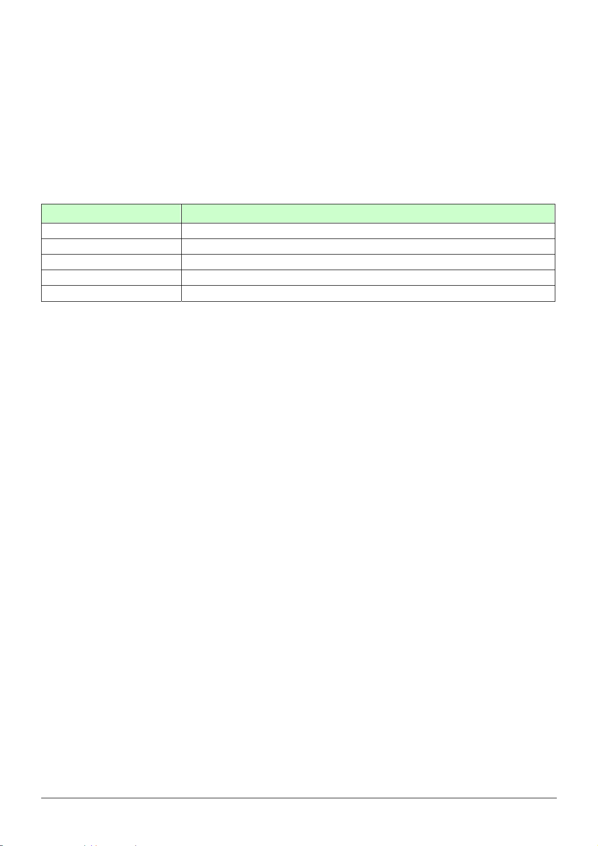
4.5 How to set TR-151A to periodically report its position by
GPRS?
Users can send an SMS by mobile phone to ask TR-151A to periodically report its position via
GPRS network to GPRS server (TR-151A call center).
The format of SMS is as below.
?9,IMEI,Report_Interval,Return_Phone_Number!
The description of SMS
Format Description
?9 Start sign and function code
IMEI IMEI of TR-151A
Report_Interval Time interval of sending data report. The unit is second.
Return_Phone_Number The phone number for receiving OK message.
! End sign
TR-151A will send an SMS whose format is“?9,IMEI,OK!” to the return phone number to confirm
it has received the request. Then it will periodically send the periodical report according to the
report interval.
Example 1: Require 120-sec period report sent to 626123456
You have to enter “?9,355632000166323,120,626123456!
Example 2: Require 180-sec period report sent to 626123456
?9,355632000166323,180,626123456!
Stop GPRS periodical report:
Users can send an SMS to stop periodical report.
The format of SMS is following as:
?2,IMEI,Return_Phone_Number!
TR-151A page 31
Page 32

4.6 Tracking/Monitoring TR-151A by GPRS
Users can make commands to TR-151A for asking immediate report, periodical report, or stop
report via GPRS server and network.
Report type
Immediate report $0,IMEI! *note1 $0,355632000166323! $OK!
0
Period report $1,IMEI,sec! *note2
1
Stop connect $2,IMEI! *note3 $2,355632000166323! $OK!
2
Format Note Example
$1,355632000166323,30!
sec= 5~86400
Report every 30 seconds
TR-151A will
return
$OK!
*note1: When TR-151A receives this command, it will send the report back immediately. It will send only one time,
and the GPRS connection is still on.
*note2: When TR-151A receives this command, it will send back the report every specified second. And the GPRS
connection is still on. The time error of return could be 1~3 seconds, or larger if the GPRS connection is not stable.
*note3: When TR-151A receives this command, it will disconnect from GRPS and go to standby mode.
TR-151A page 32
Page 33

4.7 Displaying the location on map
The format of longitudes and latitudes got from TR-151A differs from the format of Google map/earth’s
longitudes and latitudes. So users have to convert the format of longitudes and latitudes got from
TR-151A into the format Google map/earth’s longitudes and latitudes before displaying the location on
map.
The format of longitudes and latitudes got from TR-151A is like E2459.79 and N12129.26. E2459.79
means E24°59.79’. N12129.26 means N121°29.26’ Please take the digits at the right side of the degree to
be divided by 60. The number you get is the number at the right side of decimal.
For example, the longitudes and latitudes got from is E2459.79 and N12129.26
You have to take 59.79 ÷ 60 =0.9965 ; 29.26 ÷ 60=0.487666 0.4877≒
Then you can enter 24.9965 and 121.4877 into Google earth or Google map to display the location.
● Start the Google Earth software.
Input the latitude and
longitude
The Google Earth will
display the location
map for you.
TR-151A page 33
Page 34
● Or you can start the Internet Explorer and type "http://maps.google.com" to connect to Google Map
website for displaying the location map.
Input the latitude
and longitude
and click on
Search button.
The Google
Map will
display the
location
map for you.
Select "Satellite" or
"Hybrid".
It depends on Google
Map whether your
area is supported by
this mode or not.
TR-151A page 34
Page 35
4.8 How to set TR-151A enter Geofence mode?
Users can send SMS to TR-151A for setting up to 10 permissible or restricted areas whose
shape is circular or rectangular for tracking the vehicles or monitoring the equipment/assets.
Users can choose to receive alarm message while TR-151A enters the restricted areas or to
receive alarm message while TR-151A gets out the permissible areas. The content of the SMS
includes the rectangular or circular areas defined by longitudes and latitudes, getting in the
restricted areas or getting out the permissible areas to send alarm, time intervals of alarm report,
number of reports, report format and return phone number.
The format of SMS is as below.
Report type Format Return message
?4,IMEI,{[R,longitude,latitude,longitude,latitude],
4 SMS Geofence
[C,longitude,latitude,radius(meter)]},In_or_Out,
Report_Interval,Number_of_Reports,Report_Format,
Return_Phone_Number!
?4,IMEI,OK!
?11,IMEI,{[R,longitude,latitude,longitude,latitude],
GPRS
11
Geofence
[C,longitude,latitude,radius(meter)]},In_or_Out,
Report_Interval,Number_of_Reports,Report_Format,
Return_Phone_Number!
?11,IMEI,OK!
The description of SMS
Format Description
?4
?11
IMEI IMEI of TR-151A
{[R,longitude,latitude,longitude,latitude],[C,lo
ngitude,latitude,
radius(meter)]}
In_or_Out
Report_Interval Time interval of sending data report. The unit is second.
Number_of_Reports
Start sign and function code
?4 Æ Send location info to mobile phone.
?11 Æ Send location info to TR-151A call center
Boundary information:
R: rectangular shape Æ Follow by two longitudes, latitudes.
C: circular shape Æ Follow by one longitude, latitude and one
radius.
In_or_Out=in Æ Send alarm message if TR-151A gets in the
restricted areas.
In_or_Out=out Æ Send alarm message if TR-151A gets out
the permissible areas.
Set how many reports will be sent?
Number_of_Reports=0 Æ continuous report
Number_of_Reports=X Æ X times report
Report_Format
Return_Phone_Number
! End sign
Set TR-151A to return message by Format0 or Format1.
(see description below)
?4: The phone number for receiving return message and alarm
message.
?11:The phone number for receiving return message
TR-151A page 35
Page 36

Note 1:
Note 2:
The format of Google map/earth’s longitudes and latitudes differs from the format of TR-151A’s.
So please convert the format of Google map/earth’s longitudes and latitudes into the format of
TR-151A’s longitudes and latitudes before setting Geofence.
If you get a set of latitude and longitude from Google earth like 24°59’47.40” & 121°29’15.72”,
you have to convert the format to TR-151A format as below and then set geo-fence.
47.40 ÷60=0.79 15.72÷60=0.262
Please take E 12129. & 262 N2459.79 to set geo-fence
If you get a set of latitude and longitude from Google earth like 24.9965°& 121.4877°, you have
to convert the format to TR-150 format as below and then set geo-fence.
0.9965 x60=59.79 0.4877 x60=29.262
Please take E12129. 262 & N2459.79 to set geo-fence
User can set up to 10 rectangular or circular boundaries. Each SMS contains one boundary setting.
User can send numerous SMS to complete one set of settings, including numerous rectangular or
circular boundaries. For example, if user wants to set the boundary includes 2 rectangles and 1 circle.
User has to send 3 SMS, two with rectangle information, one with circle information.
SMS1:
?4,IMEI,R,longitude,latitude,longitude,latitude,In_or_Out,Report_Interval,
Number_of_Reports,Report_Format,Return_Phone_Number!
SMS2:
?4,IMEI,R,longitude,latitude,longitude,latitude,In_or_Out,Report_Interval,
Number_of_Reports,Report_Format,Return_Phone_Number!
SMS3:
?4,IMEI,C,longitude,latitude,radius,In_or_Out,Report_Interval,
Number_of_Reports,Report_Format,Return_Phone_Number!
If user uses numerous SMS in one setting, the IMEI, In_or_Out, Report_Interval, Number_of_Reports,
Report_Format, Return_Phone_Number must be the same between each SMS. If above parameters
are not the same between SMS, TR-151A only follows last SMS.
Note 3
In Boundary information
{[R,longitude,latitude,longitude,latitude],[C,longitude,latitude,radius],}
User can set
TR-151A page 36
Page 37

Note 4:
R: rectangular follows by two longitudes and two latitudes.
Or
C: circular follows by one longitude, one latitude and one radius.
Example: Rectangle
R,E12128.1883,N2342.8117,E12129.2186,N2459.8915
Example: Circle (radius is 1000 meters)
C,E12129.2186,N2459.8915,1000
Example:
Send one SMS to setup Geofence.
Boundary includes one rectangle (two longitudes and two latitudes Æ
E12128.1883,N2342.8117,E12129.2186,N2459.8915)
When TR-151A gets out boundary, it would send format1, 10 times, 120 sec interval, alarm
message to 626123456.
?4,355632000166323,R,E12128.1883,N2342.8117,E12129.2186,N2459.8915,out,120,10,1,616123456!
Example:
Send three SMS to setup Geofence.
Boundary includes one rectangle (two longitudes and two latitudes Æ
E12128.1883,N2342.8117,E12129.2186,N2459.8915) and t wo circles (one longitude/latitude is
E12228.1883,N2442.8117, and radius is 1000 meter ) ( the other longitude/latitude is
E12328.1883,N2452.8117, and radius is 1500 meter)
When TR-151A gets out boundary, it would send format1, 10 times, 120 sec interval, alarm
message to 626123456.
SMS1:
?4,355632000166323,R,E12128.1883,N2342.8117,E12129.2186,N2459.8915,out,120,10,1,616123456!
SMS2:
?4,355632000166323,C,E12228.1883,N2442.8117,1000,out,120,10,1,616123456!
SMS3:
?4,355632000166323,C,E12328.1883,N2542.8117,1500,out,120,10,1,616123456!
Exit Geofence mode:
Users can send an SMS exit Geofence mode.
The format of SMS is following as:
?2,IMEI,Return_Phone_Number!
Caution:
If you exit Geofence mode, all the settings will be deleted.
TR-151A page 37
Page 38
4.9 How to make TR-151A do Voice monitor function?
User can send a SMS by a mobile phone to ask TR-151A start the voice monitoring.
The format of SMS is following as:
?6,IMEI,Return_Phone_Number!
The table below explains the content of the SMS
Format Description
? Start sign
6 Function code
IMEI IMEI code of the TR-151A
Return_Phone_Number The phone number for TR-151A to call back and transmit the sounds.
! End sign
Note: If return phone number is empty, TR-151A will call back to Caller ID
TR-151A will send an SMS whose format is“?6,IMEI,OK!” to the return phone number to confirm
it has received the request. And then it will start to call back to the returned number written in the
SMS. And then user can listen to the sound or voice around TR-151A.
Example:
User send voice command and make TR-151A call back to 626123456
?6,355632000166323,626123456!
Stop voice monitoring:
Users can hang up the phone call to stop voice monitoring.
TR-151A page 38
Page 39
4.10. How to set TR-151A enter Parking Mode?
Parking Mode is for users to make TR-151A to send out an alarm SMS to inform user while it
senses vibration.
Users can use Call Center or SMS to configure parameters: Enable parking time, telephone
number, time interval and number of report.
While the device is powered on, press the power button to enter parking mode. The status
LED will flash specific times to indicate the parking mode is enabled.
Press the power button again to exit from the parking mode.
User can also send an SMS by a mobile phone to set the parameters of parking mode.
The format of SMS is following as:
?7,IMEI,5,Park_Time,Park_Interval,Park_Number_of_Reports,Report_format,Sensitivity,Park_R
eturn_Number,Return_Phone_Number!
The table below explains the content of the SMS
Format Description
?7 Start sign and function code
IMEI IMEI of TR-151A
5 Setting code for Parking setting
Park_Time Set the active time for entering parking mode. The unit is second.
Park_Interval Time interval of sending data report. The unit is second.
Set how many report will be sent.
Park_Number_of_Reports
Report format
Sensitivity
Park_Return_Number Return phone number for default report mode.
Return_Phone_Number
! End sign
0 Æ continuous report
X Æ X times report
0 Æ Format0
1 Æ Format1
Set the number of vibration which enables TR-151A to send out alarm. The
number you can set is 1~255. Larger value means less sensitive.
The confirmed SMS sent to the phone number to indicate the setting is
successful.
TR-151A will send an SMS whose format is“?7,IMEI,OK!” to the return phone number to confirm
it has received the request.
Exit from parking mode:
Users can press the power button or send an SMS to exit from parking mode.
The format of SMS is following as:
?2,IMEI,Return_Phone_Number!
TR-151A page 39
Page 40
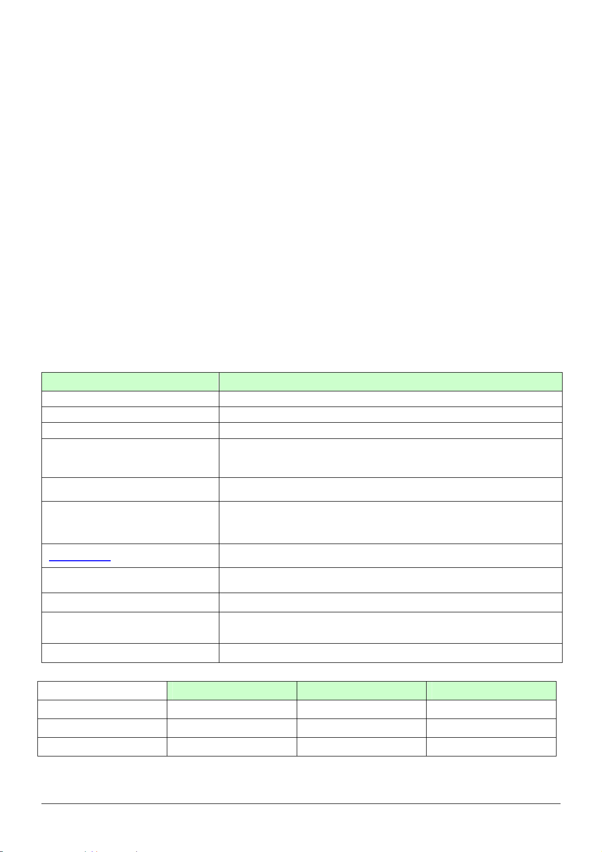
4.11 How to set TR-151A enter Sleeping Mode?
Sleeping Mode is for users to make TR-151A to send out an alarm SMS to inform user while it
senses vibration. During sleeping mode, TR-151A does not connect to GSM network. So
TR-151A cannot receive SMS during sleeping mode.
DIP switch 4 ON: Enable sleeping mode DIP switch 4 OFF: Disable sleeping mode
When DIP switch 4 is on, and the device is powered on, it would enter the sleeping mode. The
status LED will flash 60 times to indicate the sleeping mode is enabled.
User can also send an SMS by a mobile phone to configure the parameters of sleeping mode.
The format of SMS is following as:
7,IMEI,6,Sleep_Time,Sleep_Interval,Sleep_Number_of_Reports,Report_format,Sensitivity,Slee
p_Return_Number,Return_Phone_Number!
The table below explains the content of the SMS
Format Description
?7 Start sign and function code
IMEI IMEI of TR-151A
6 Setting code for Sleeping setting
Set the time length of sleep mode. The unit is hour. When it reaches the
Sleep_Time
Sleep_Interval
Sleep_Number_of_Reports
Report format
Sensitivity
Sleep_Return_Number Return phone number for default report mode.
Return_Phone_Number
! End sign
Sleep Time, TR-151A will wake up and send a SMS message, then go
back to Sleeping mode.
Time interval of sending data report when TR-151A senses the vibration
under sleeping mode. The unit is second.
Set how many report will be sent.
0 Æ continuous report
X Æ X times report
0 Æ Format0
1 Æ Format1
Set the number of vibration which enables TR-151A to send out alarm. The
number you can set is 1~255. Larger value means less sensitive.
The confirmed SMS sent to the phone number to indicate the setting is
successful.
Comparison between parking mode, sleeping mode, and normal mode
Function/Mode
GPS
GSM
Motion sensor
TR-151A page 40
Normal mode Parking mode Sleeping mode
Off Off
On On Off
Off On On
Page 41
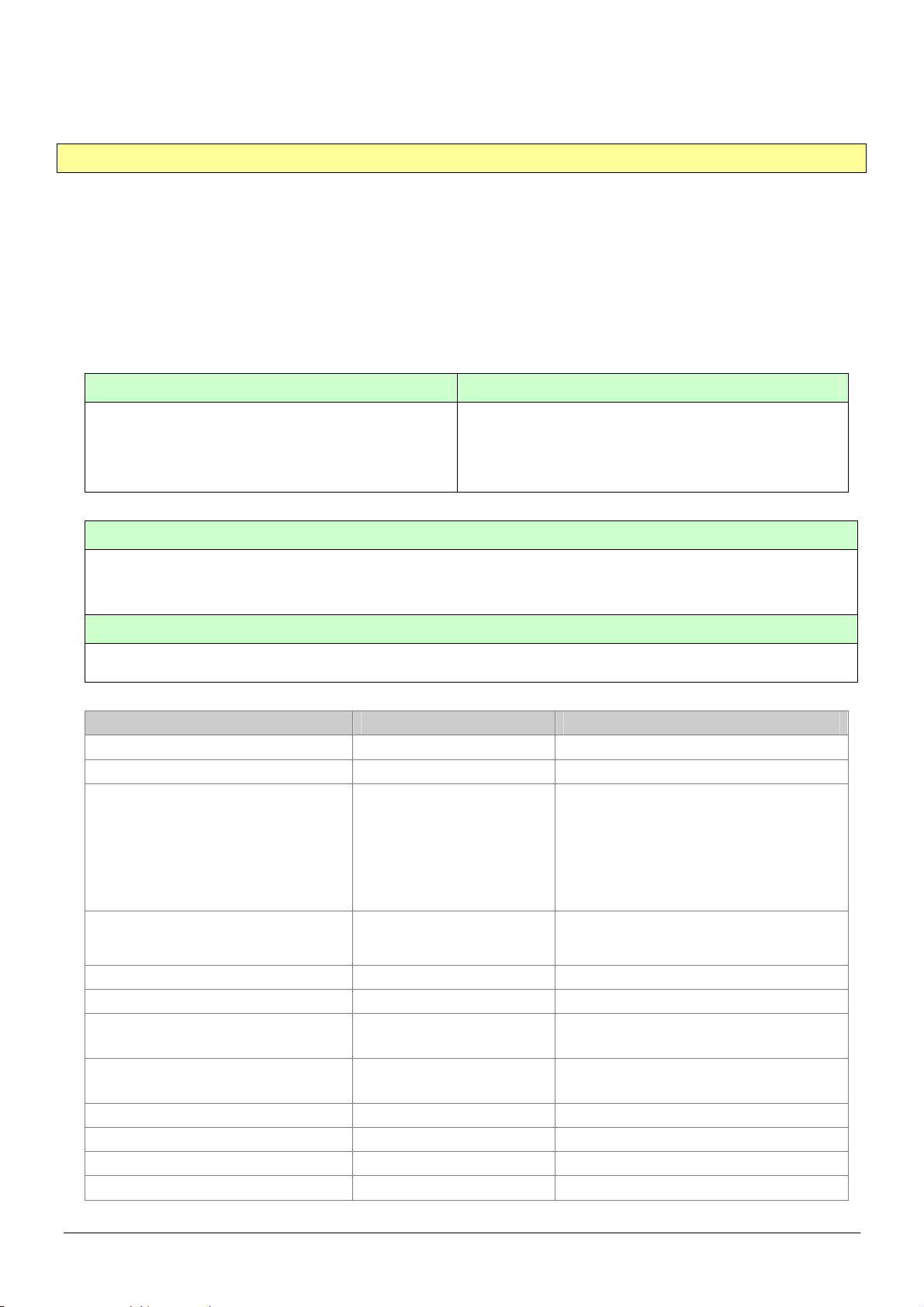
4.12 The return format from TR-151A
Return SMS format from TR-151A
The data format is configurable in the SMS tracking commands. There are two types of the data
format as below.
Format0 is for general end users who send SMS commands to TR-151A by their cell phone or
PDA phone. This format is very easy to read by end users.
Format1 is specifically read by software Call Center that is developed by service provider.
Data Report Format:
Report_Format=0 Æ Format0
Report_Format=1 Æ Format1
Format0: Example:
Position report
Name
Time Date
GPS position
Fix or not
Format1:
Position report
Name
2006/9/15 10:20:39
N2459.8915,E12129.2186
GPS fixed
?IMEI,Status,GPS_Fix,Date,Time,Longitude,Latitude,Altitude,Speed,
Heading,Number_of_Satellites_In_Use,HDOP!
Example:
?353857014816785,2,3,280807,035825,E12129.2616,N2459.7918,97.2,0.13,142.31,04,2.4!
The description of Format1
Format Value Note
? ? Command Head
IMEI The number of IMEI
Status 0
1
2
4
12
13
GPS_Fix
Date ddmmyy
Time hhmmss
Longitude (E or W)dddmm.mmmm Example:
Latitude (N or S)ddmm.mmmm Example:
Altitude xxxxx.x unit: meters
Speed xxxxx.xx unit: knots (1knots = 1.852km)
Heading ddd
Number_of_Satellites_In_Use xx
1
2
3
0: Immediate report
1: Period report
2: Stop report
4: Geofence
12: Parking
13: Sleeping
1: Fix not available
2: GPS 2D Fix
3: GPS 3D Fix
E12129.2186 Æ E 121°29.2186’
N2459.8915 Æ N 24°59.8915’
TR-151A page 41
Page 42
HDOP x.x
! ! Command End
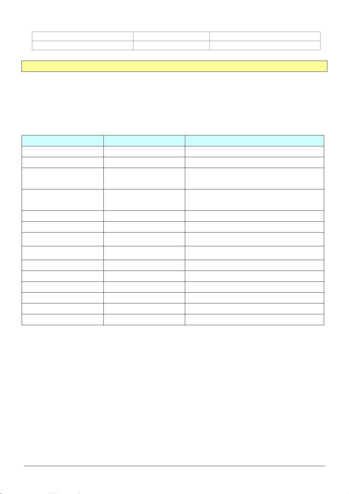
Format of return GPRS from TR-151A
Format:
Command_Head,IMEI,status,GPS_fix,date,time,longitude,latitude,altitude,speed,heading,number of satellites in
use,HDOP,Command_End
Example:
$355632000166323,1,1,040202,093633,E12129.2252,N2459.8891,00161,0.0100,147,07,2.4!
Format Value Note
Command_Head $
IMEI (The number of IMEI)
Status
GPS_fix
date ddmmyy
time hhmmss
longitude (E or W)dddmm.mmmm
latitude (N or S)ddmm.mmmm
altitude xxxxx.x unit: meters
speed xxxxx.xx unit: knots (1knots = 1.852km)
heading ddd
number of satellites in use xx
HDOP x,x
Command END !
0
1
2
1
2
3
0: Immediate report
1: Period report
2: Stop connect
1: Fix not available
2: GPS 2D Fix
3: GPS 3D Fix
Example:
E12129.2186 → E 121°29.2186’
Example:
N2459.8915 →N 24°59.8915’
TR-151A page 42
Page 43
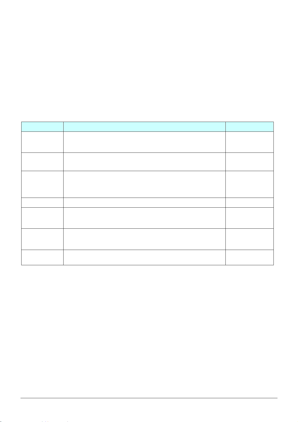
4.13 SMS Configuration
User can configure following parameters into TR-151A by SMS. There are seven settings as
below.
z SMS Default Return Phone Number
z Maximum GPS Fixing Time
z Default Report Mode Setting
z SOS Numbers
z Parking setting
z Sleeping setting
z GPRS setting
Report type Format Return message
SMS Default
Return Phone
Number
Maximum GPS
Fixing Time
Default Report
Mode Setting
SOS Numbers ?7,IMEI,4,SOS1,SOS2,SOS3,Return_Phone_Number! ?7,IMEI,OK!
Parking Setting ?7,IMEI,5,Park_Time,Park_Interval,
Sleeping
Setting
GPRS Setting ?7,IMEI,7,Port,APN,GPRS_Name,GPRS_pwd,DNS1,DNS2,
?7,IMEI,1,Enable_SMSDefaultReturnPhoneNumber,
SMSDefaultReturnPhoneNumber,Return_Phone_Number!
?7,IMEI,2,Maximum_GPS_Fixing_Time,
Return_Phone_Number!
?7,IMEI,3,Default_Report_Mode,Report_Interval,
Number_of_Reports,Report_Format,
ReturnPhoneNnumberForDefaultReportMode,
Return_Phone_Number!
Park_Number_of_Reports,Report_Format,sensitivity,
Park_Return_Number,Return_Phone_Number!
?7,IMEI,6,Sleep_Time,Sleep_Interval,
Sleep_Number_of_Reports,Report_Format,sensitivity,
Sleep_Return_Number,Return_Phone_Number!
Host_Name,Return_Phone_Number!
?7,IMEI,OK!
?7,IMEI,OK!
?7,IMEI,OK!
?7,IMEI,OK!
?7,IMEI,OK!
?7,IMEI,OK!
Default_Report_Mode:
Default_Report_Mode = 0 Æ immediate report
Default_Report_Mode = 1 Æ period report
Default_Report_Mode = 2 Æ stop
Enable_SMSDefaultReturnPhoneNumber:
Enable or disable SMS Default Return Phone Number.
Enable_SMSDefaultReturnPhoneNumber = 0 Æ Disable
Enable_SMSDefaultReturnPhoneNumber = 1 Æ Enable
Maximum_GPS_Fixing_Time:
If GPS is not fixed within the time, it returns previous location and close GPS.
The unit is minute.
Number_of_Reports:
Set how many report will be sent.
Number_of_Reports = 0 Æ continuous report
Number_of_Reports = X Æ X times report
Report_Format: Ask TR-151A to return message by Format0 or Format1.
Report_Interval: Time interval of sending data report. The unit is second.
TR-151A page 43
Page 44

Return_Phone_Number: TR-151A will send confirmed message back to this Return_Phone_Number.
If user let Return_Phone_Number be empty, TR-151A will send report back to
SMSDefaultReturnPhoneNumber.
If Return_Phone_Number and SMSDefaultReturnPhoneNumber are both empty, TR-151A
will send report back to caller ID.
ReturnPhoneNnumberForDefaultReportMode: Return phone number for default report mode. TR-151A will
send report to this number after it is turned on when Default Report Mode is set to immediate
report or period report.
SMSDefaultReturnPhoneNumber: Set SMS Default Return Phone Number.
TR-151A page 44
Page 45
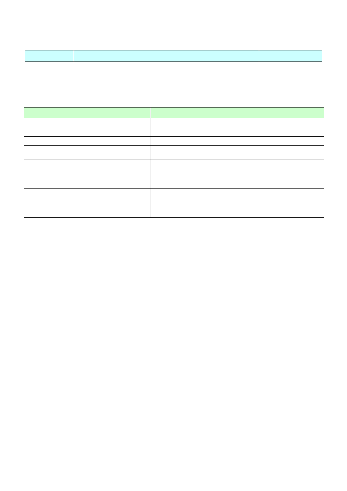
4.13.1 SMS Configuration _ SMS Default Return Phone Number
Report type Format Return message
SMS Default
Return Phone
Number
?7,IMEI,1,Enable_SMSDefaultReturnPhoneNumber,
SMSDefaultReturnPhoneNumber,Return_Phone_Number!
?7,IMEI,OK!
The description of SMS
Format Description
?7 Start sign and function code
IMEI IMEI of TR-151A
1 Setting code for SMS Default Return Phone Number
Enable_SMSDefaultReturnPhoneNumber
SMSDefaultReturnPhoneNumber
Return_Phone_Number
! End sign
0 Æ Disable
1 Æ Enable
In the SMS tracking commands (immediate report, period report,
stop report, Geofence), if the field Return_Phone_Number is
empty, TR-151A will send data report to this
SMSDefaultReturnPhoneNumber.
The confirmed SMS sent to the phone number to indicate the
setting is successful.
Example: To configure SMS default return phone number as 313-987654, and send confirmed SMS to
626-123456.
?7,355632000166323,1,1,313987654,626123456!
Example: To Disable SMS default return phone number and send confirmed SMS to 626-123456.
?7,355632000166323,1,0,,626123456!
TR-151A page 45
Page 46
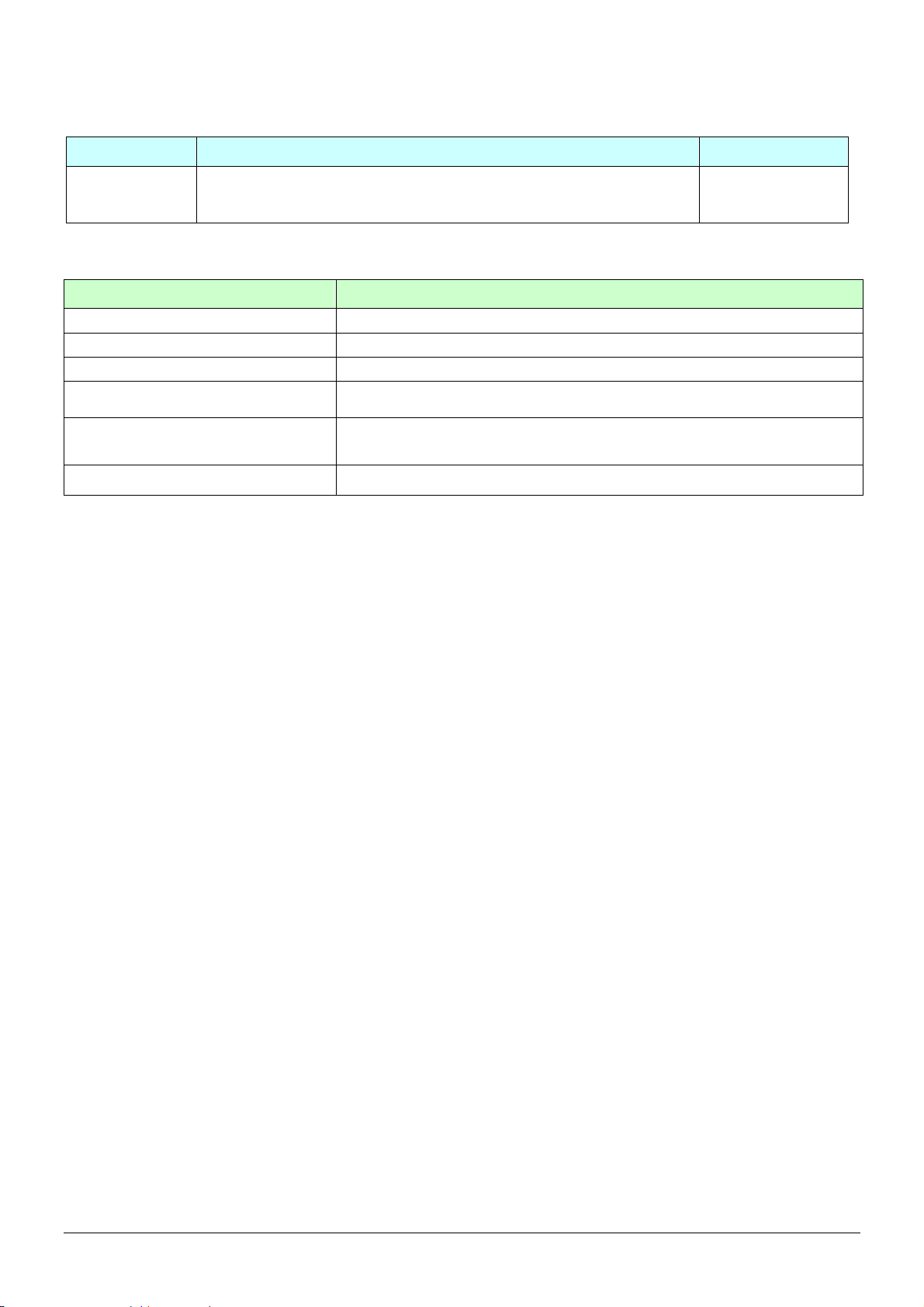
4.13.2 SMS Configuration _ Maximum GPS Fixing Time
Report type Format Return message
Maximum GPS
fixing time
?7,IMEI,2,Maximum_GPS_Fixing_Time,
Return_Phone_Number!
?7,IMEI,OK!
The description of SMS
Format Description
?7 Start sign and function code
IMEI IMEI of TR-151A
2 Setting code for Maximum GPS fixing time
Maximum_GPS_Fixing_Time
Return_Phone_Number
! End sign
The time that allows for GPS fixing. If GPS fixing is not achieved within the
time, it will close GPS and send back the previous location info.
The confirmed SMS sent to the phone number to indicate the setting is
successful.
Example: To configure Maximum GPS fixing time to 5 minutes and send confirmed SMS to 626-123456.
?7,355632000166323,2,5,626123456!
TR-151A page 46
Page 47
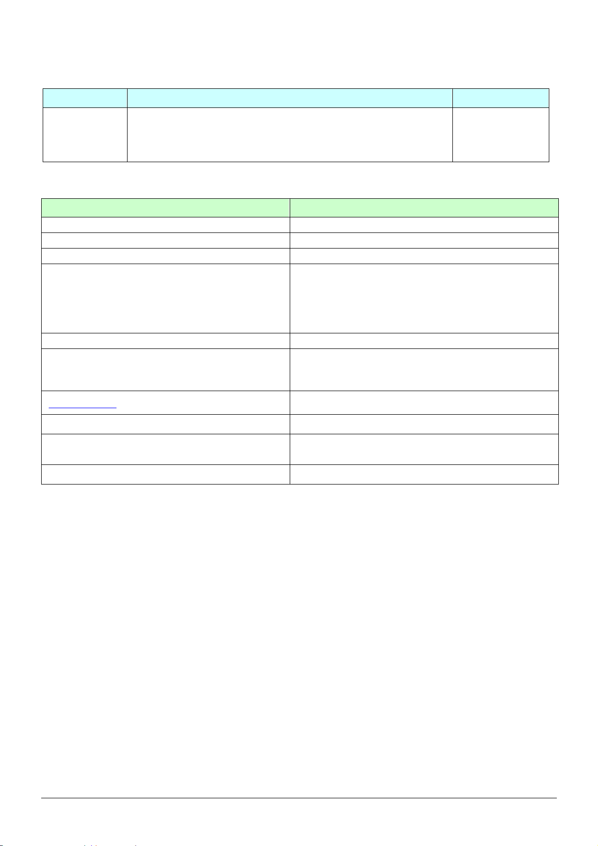
4.13.3 SMS Configuration _ Default Report Mode Setting
Report type Format Return message
Default report
mode setting
?7,IMEI,3,Default_Report_Mode,Report_Interval,
Number_of_Reports,Report_Format,
ReturnPhoneNnumberForDefaultReportMode,
Return_Phone_Number!
?7,IMEI,OK!
The description of SMS
Format Description
?7 Start sign and function code
IMEI IMEI of TR-151A
3 Setting code for Default report mode setting
0 Æ SMS immediate report
1 Æ SMS periodical report
Default_Report_Mode
Report_Interval Time interval of sending data report. The unit is second.
Number_of_Reports
Report_Format
ReturnPhoneNnumberForDefaultReportMode Return phone number for default report mode.
2 Æ stop
8 Æ GPRS immediate report
9 Æ GPRS periodical report
Set how many report will be sent.
0 Æ continuous report
X Æ X times report
0 Æ Format0
1 Æ Format1
Return_Phone_Number
! End sign
The confirmed SMS sent to the phone number to indicate
the setting is successful.
Note:
The configuration is for default report mode (SMS Immediate, SMS Period, Stop, GPRS immediate, GPRS
periodical) settings. In immediate and stop settings, some fields are unnecessary, please leave these fields empty
and separate them by a comma. Please see following examples for detail.
Example:
SMS Immediate report. Configure default report mode as SMS immediate report, send format1
report data to 313-987654, and send confirmed SMS to 626-123456.
?7,355632000166323,3,0,,,1,313987654,626123456!
Example: SMS Period report. Configure default report mode as SMS period report, send 10 times, 180-sec
period report in format0 to 313-987654, and send confirmed SMS to 626-123456.
?7,355632000166323,3,1,180,10,0,313987654,626123456!
Example: Stop. Configure default report mode as stop (standby), and send confirmed SMS to 626-123456.
?7,355632000166323,3,2,,,,,626123456!
Example:
GPRS Period report. Configure default report mode as GPRS period report, send 180-sec period
report, and send confirmed SMS to 626-123456.
?7,355632000166323,3,9,180,,,,626123456!
TR-151A page 47
Page 48
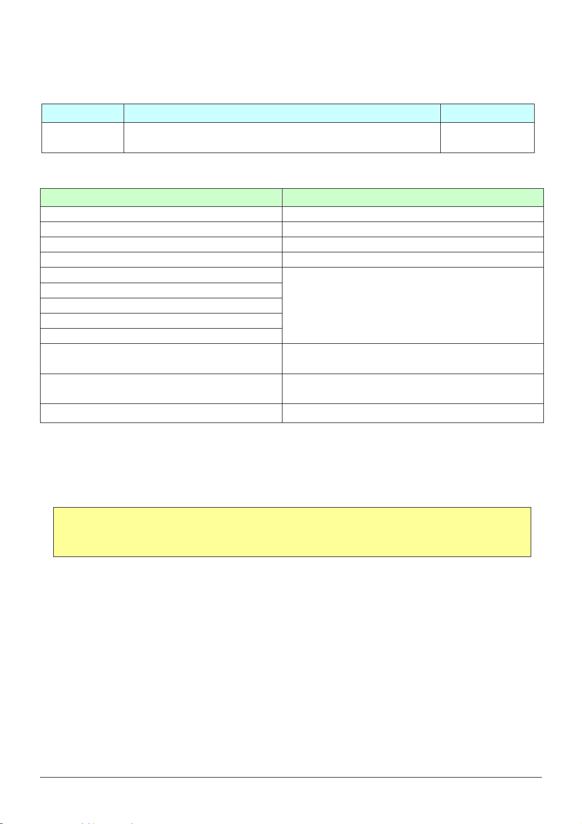
4.13.4 SMS Configuration _ GPRS Setting
Report type Format Return message
GPRS Setting ?7,IMEI,7,Port,APN,GPRS_Name,GPRS_pwd,DNS1,DNS2,
Host_Name,Return_Phone_Number!
?7,IMEI,OK!
The description of SMS
Format Description
?7 Start sign and function code
IMEI IMEI of TR-151A
7 Setting code for GPRS setting
Port GPRS Port of the Server
APN
GPRS_Name
GPRS_pwd
DNS1
DNS2
Host_Name
Return_Phone_Number
! End sign
Please consult your GPRS network service provider for
these parameter values.
Please enter the physical IP of the PC where you install
TR-151A call center or the domain name.
The confirmed SMS sent to the phone number to indicate
the setting is successful.
Note: TR-151A is designed for vehicle and asset for tracking purpose, not
for carried by people.
TR-151A page 48
Page 49

Federal Communication Commission Interference Statement:
This equipment has been tested and found to comply with the limits for a Class B digital device, pursuant to Part 15
of the FCC Rules. These limits are designed to provide reasonable protection against harmful interference in a
residential installation. This equipment generates uses and can radiate radio frequency energy and, if not installed
and used in accordance with the instructions, may cause harmful interference to radio communications. However,
there is no guarantee that interference will not occur in a particular installation. If this equipment does cause harmful
interference to radio or television reception, which can be determined by turning the equipment off and on, the user
is encouraged to try to correct the interference by one of the following measures:
Reorient or relocate the receiving antenna.
Increase the separation between the equipment and receiver.
Connect the equipment into an outlet on a circuit different from that to which the receiver is connected.
Consult the dealer or an experienced radio/TV technician for help.
This device complies with Part 15 of the FCC Rules. Operation is subject to the following two conditions:
(1) This device may not cause harmful interference, and
(2) this device must accept any interference received, including interference that may cause undesired operation.
FCC Caution: Any changes or modifications not expressly approved by the party responsible for compliance could
void the user's authority to operate this equipment.
TR-151A page 49
Page 50

IMPORTANT NOTE:
FCC Radiation Exposure Statement:
This equipment complies with FCC radiation exposure limits set forth for an uncontrolled environment. End users
must follow the specific operating instructions for satisfying RF exposure compliance. To maintain compliance with
FCC RF exposure compliance requirements, please follow operation instruction as documented in this manual.
“For body worn operation, this Tracker has been tested and meets FCC RF exposure guidelines when used with
an accessory that contains no metal and that positions the device a minimum of 1.5 cm from the body. Use of other
accessories may not ensure compliance with FCC RF exposure guidelines.”
Radio wave exposure and Specific Absorption Rate (SAR) information:
This mobile Tracker (model number TR-151A) has been designed to comply with applicable safety requirement for
exposure to radio waves. This requirement is based on scientific guidelines that include safety margins designed to
assure this safety of all persons, regardless of age and health.
The radio wave exposure guidelines employ a unit of measurement known as the Specific Absorption Rate, or SAR.
Tests for SAR are conducted using standardized method with the phone transmitting at its highest certified power
level in all used frequency bands.
While there may be differences between the SAR levels of various phone models, they are all designed to meet the
relevant guidelines for exposure to radio waves.
The highest SAR value for this model phone tested by DASY5 for use at the ear is 0.699 W/kg.
SAR data information for residents in countries/regions that have adopted the SAR limit recommended by the
Institute of Electrical and Electronics Engineers (IEEE), which is 1.6 W/kg averaged over one (1) gram of tissue.
TR-151A page 50
 Loading...