

Page 1
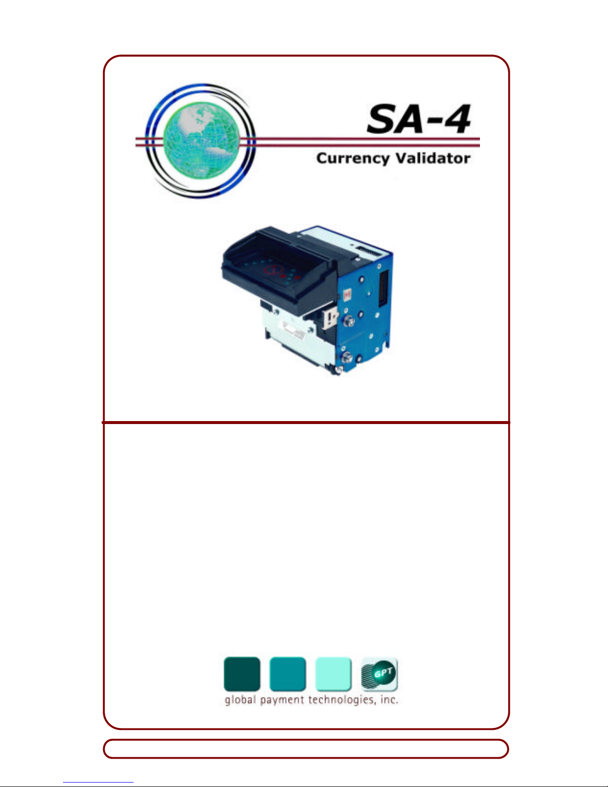
SA-4 Down -Stack Unit
Installation Guide
for
SA-4
Currency Validators
Publication Number: G3M5111
1 April 2005
Visit our Web site at www.gpt.com
Page 2
Global Payment Technologies, Inc.
Page 2 G3M5111
Important Notice
Global Payment Technologies, Inc. (the Company), reserves the right to make
changes to the contents of this publication, including functions and specific ations identified herein, without notice.
In the absence of a written agreement to the contrary, the Company, assumes
no liability for the applications assistance, customer’s product/application/concepts, or infringements of patents or copyrights of third
parties arising from the use of products methods and architectures described
herein. Nor does the Company, warrant or represent that any license, either
expressed or implied, is granted under any patent right, copyright, or other
combination of technology, architecture, or software as might be or is already
in use.
Note: The material in this document is only intended for use
by the Company, its employees and any licensed or authorized user of its proprietary products and/or software.
The techniques, procedures and information described herein are Conf idential Information and should not be reproduced, disseminated, or
otherwise disclosed without prior written consent from an officer of the
Company. Any authorized licensee or user specifically acknowledges
that such techniques, procedures and information comprise valuable
trade secrets and proprietary property of the Company and that all patent, copyright, trade secrets, trade/service mark, and any other right, title
or interest therein are the sole property of the Company.
This document has been copyrighted by the Company. The presence of any
copyright notice within or upon the medium containing the Company’s proprietary products shall not be construed as constituting any publication, any
intention to publish or otherwise impairing the confidential nature thereof.
Change History
Throughout its life, this document will undergo changes that reflect improvements to the document and product line. Dates of issue for the original manual
and subsequent revisions thereto are listed below:
Revision Status Reason Date
Original Issue -- 1 April 2005
© 2005 Global Payment Technologies, Inc.
Note: A copy of this document is available at GPT’s Web site:
www.gpt.com/
Page 3

Installation Guide
G3M5111 Page 3
Table of Contents
1. INTRODUCTION.....................................................................................5
2. UNPACKING AND INSPECTION.........................................................5
2.1 UNPACKING............................................................................................6
2.2 INSPECTION.............................................................................................6
3. PRODUCT OVERVIEW..........................................................................6
3.1 SPECIFICATIONS......................................................................................8
3.2 IDENTIFYING YOUR CURRENCY VALIDATOR...........................................9
3.3 MAIN CONNECTOR................................................................................12
3.4 COMMUNICATION PROTOCOLS..............................................................13
4. INSTALLATION INSTRUCTIONS.....................................................13
4.1 INSTALLATION PROCEDURE ..................................................................13
5. BEZEL LED DISPLAYS........................................................................17
5.1 DISPLAYS FOR NORMAL EQUIPMENT OPERATION .................................17
5.2 SELF-DIAGNOSTIC ERROR DISPLAYS....................................................19
6. TROUBLESHOOTING..........................................................................20
7. PERIODIC CLEANING ........................................................................22
7.1 CLEANING THE BEZEL...........................................................................22
7.2 CLEANING THE CURRENCY CHANNEL...................................................22
7.2.1 Required Items ...............................................................................22
7.2.2 Procedure........................................................................................22
8. VIDEO-LEVEL ADJUSTMENT ..........................................................25
8.1 REQUIRED ITEMS ..................................................................................25
8.2 PROCEDURE..........................................................................................26
8.3 DESCRIPTION OF VLA PROCESS ...........................................................27
8.4 PRECAUTIONS.......................................................................................27
9. REQUESTING SERVICE......................................................................28
9.1 COMPANY DIRECTORY..........................................................................28
Page 4

Global Payment Technologies, Inc.
Page 4 G3M5111
List of Figures
Figure 1. SA -4 Currency Validators..........................................................5
Figure 2. SA -4 Currency Validator and Universal SRC............................7
Figure 3. Currency Validator Label Identification....................................9
Figure 4. Part Number Label Numbering Scheme ....................................9
Figure 5. Program Label Numbering Scheme – Single-Country
Database................................................................................10
Figure 6. Program Label Numbering Scheme – Multi-Country
Database................................................................................11
Figure 7. Currency Validator 22-Pin Main Connector............................12
Figure 8. SA -4 Validator Heads – Component Locations.......................14
Figure 9. Attaching Cable Connector to Main Connector.......................15
Figure 10. Universal SRC – Back View of Internal Parts.......................21
Figure 11. Currency Channel – Cleaning Surfaces for SA-4 Down-
Stack Unit .............................................................................24
Figure 12. 10-Pack DIP-Switch Package.................................................26
List of Tables
Table 1. Currency Validator Troubleshooting Chart...............................20
Table 2. Stacker Troubleshooting Chart..................................................21
Page 5
Installation Guide
G3M5111 Page 5
1. INTRODUCTION
Global Payment Technologies, Inc., welcomes you to our newest generation of Currency Validators known as SA-4. This product continues
our tradition of providing the very best in currency validation.
This guide describes installation, operation, simple troubleshooting,
and cleaning instructions for the back-stack and down -stack versions
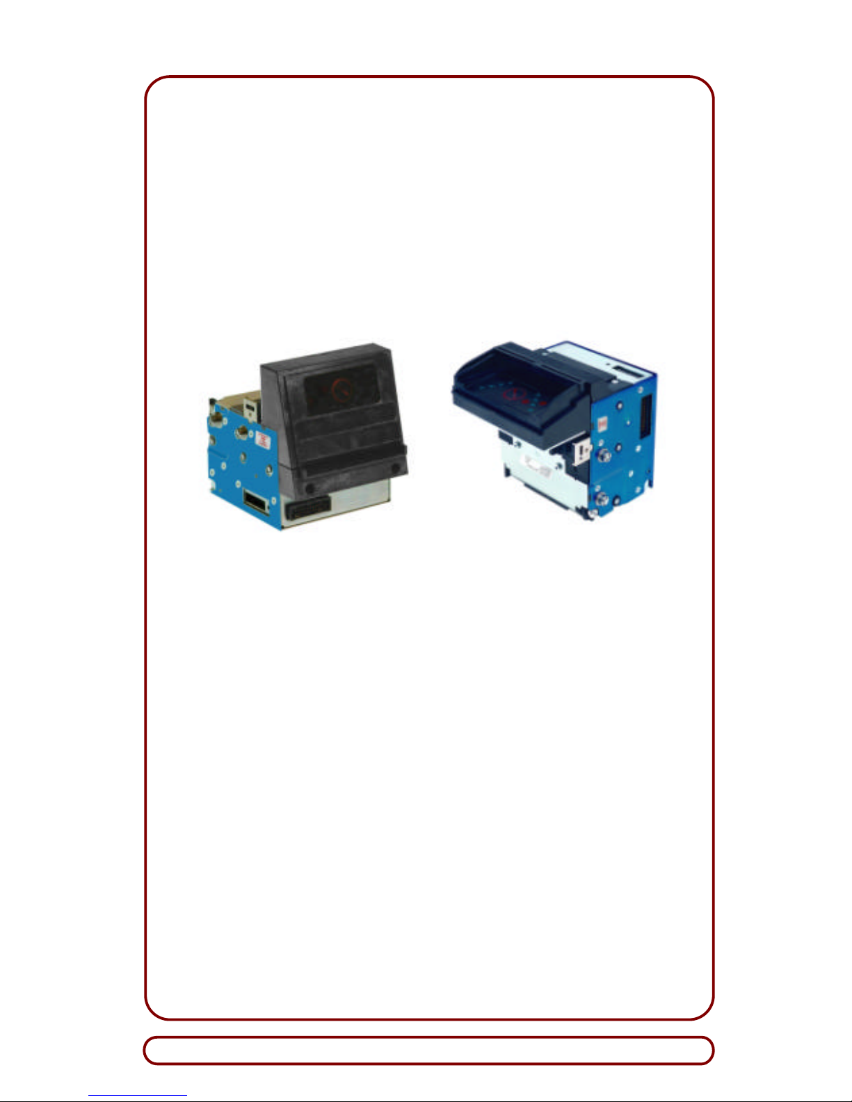
of our SA-4 product line (Figure 1). Both versions of SA-4 can be
identified by the Part Number label. For sample part numbers that denote these versions, refer to Subsection 3.2.
SA-4 Back-Stack Unit SA-4 Down-Stack Unit
Figure 1. SA-4 Currency Validators
2. UNPACKI NG AND INSPECTION
The Currency Validator and Security Removable Cassette are packaged with sufficient cushioning material to protect the equipment
during shipment. However, the shipping box or carton should be inspected for any signs of shipping damage (e.g., dents, breaks,
water/moisture damage), or other evidence of general mishandling.
If damage is found, file a complaint with the carrier, noting all damage,
and notify GPT of such action. Also, retain the original shipping box
and packaging material for inspection. Whenever possible, taking a
photograph of the damaged area may prove useful in documenting the
damage.
Page 6

Global Payment Technologies, Inc.
Page 6 G3M5111
2.1 Unpacking
To unpack the equipment, proceed as follows:
?? Cut sealing tape at top of box and open the box.
?? Remove all parts from the bo x and lay them on a clean work-
station.
?? Refer to invoice, packing slip or shipment breakdown label
(used on cartons only) for a complete list of parts, and verify
that all parts are present.
?? Do not discard the shipping box until after all items pass in-
spection.
2.2 Inspection
After the equipment is removed from the shipping box or carton, inspect the following items:
?? External surfaces of the unit for signs of damage.
?? Connectors for physical damage, broken or bent pins.
?? Cables and accessories for physical damage, broken connec-
tors, and broken or bent pins.
If an item is damaged, report it to the carrier and to GPT immediately.
Also, do not discard the shipping box and its packaging material.
3. PRODUCT OVERVIEW
SA-4, which is available in a back-stack or a down-stack configuration,
has many features similar to our ARGUS unit. However, this model
validator provides a faster processing time of less than 200th/second
to validate currency. It also includes a front-drive axle with O-rings for
increased torque and Bando drive belts for reliable operation and
longer life.
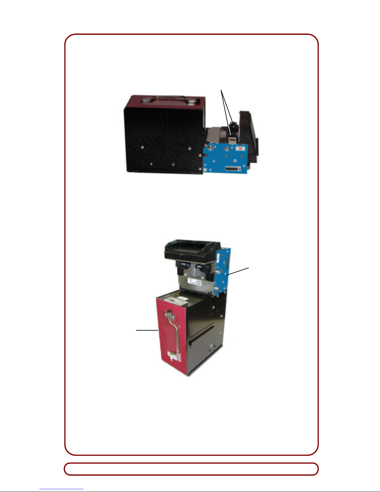
For storing currency, a Security Removable Cassette (SRC) can be
mounted either directly below or behind the Currency Validator (Fig-
ure 2). The addition of a 400-bill, Universal SRC, provides maximum
security for storing currency from 62 -mm to 85-mm wide. For all currency sizes, the Universal SRC is the only stacker needed for the
Currency Validator.
Designed with a configurable head, SA-4 is easily adaptable to meet
the needs of different customers. For customers who wish to use their
existing 70-mm SRCs for storing narrow-width cu rrencies (i.e., up to
70-mm), SA-4 can be fitted with a specially-designed bezel and channel inserts. With this configuration, GPT’s 70-mm SRC can be used
instead of the Universal SRC to store narrow-width currencies.
Page 7
Installation Guide
G3M5111 Page 7
SA-4 Back-Stack Currency Validator
SA-4 Down-Stack Currency Validator
Figure 2. SA-4 Currency Validator and Universal SRC
Spring
-
Loaded Latches
(Simultaneously release both latches to access
the currency channel.)
Currency
Validator
400-Bill
Universal
Security
Removable
Cassette
Page 8

Global Payment Technologies, Inc.
Page 8 G3M5111
The electrical interface between the Currency Validator and the SRC
is made by a blind-mate connector (i.e., standard AMP) or by an external cable (i.e., pigtail) connector. With either option, the Currency
Validator can be easily removed as needed.
3.1 Specifications
The mechanical and electrical specifi cations of the Currency Validator
are:
?? Bank Notes Accepted:
Four-direction acceptance of bank notes from 2.44 inches
(62-mm) to 3.35 inches (85-mm) wide; a range from 40 to
128 bank notes per database can be created for multicountry, multi-note configur ations.
?? Optics:
Uses red, green, blue, and infrared sensors to generate 56
channels of optical information for a multi-level, high-security
validation time of less than 200th/sec (maximum without a
SRC installed).
?? Interface/Protocol:?
RS-232/V2.2 Protocol?
?? Environment:
Operating Temperature: 0°C to 60°C
Storage Temperature: -20°C to 70°C
Humidity: 0% to 95% (non-condensing)
?? Power Source Required – Standard Operating Voltages are:
For 24 VDC unit: GPT Switching Power Su pply, Model
175C0213, or
ELPAC Power Systems1, Model FW5024
For 12 VDC unit: ELPAC Power Systems1, Model FW3012
?? Power Consumption:
Idle State: 7 Watts (max.)
Accepting/Stacking States: 24 Watts (max.)
In-rush Current: 4.5 amperes (max., current limited) for
5 milliseconds at 24 VDC
?? Compliance:
ETL (UL-756)
CSA 22.2
Testable parameters comply with CE requirements.
?? Shipping Weight (Approximate):
2.43 lbs (1.1kg) without SRC;
7.25 lbs (3.3 kg) with 400-bill SRC.
1
Power Supply Adapter Cable Assembly (GPT PN 300EX009) is required for
use with this power supply.
Page 9
Installation Guide
G3M5111 Page 9
3.2 Identifying Your Currency Validator
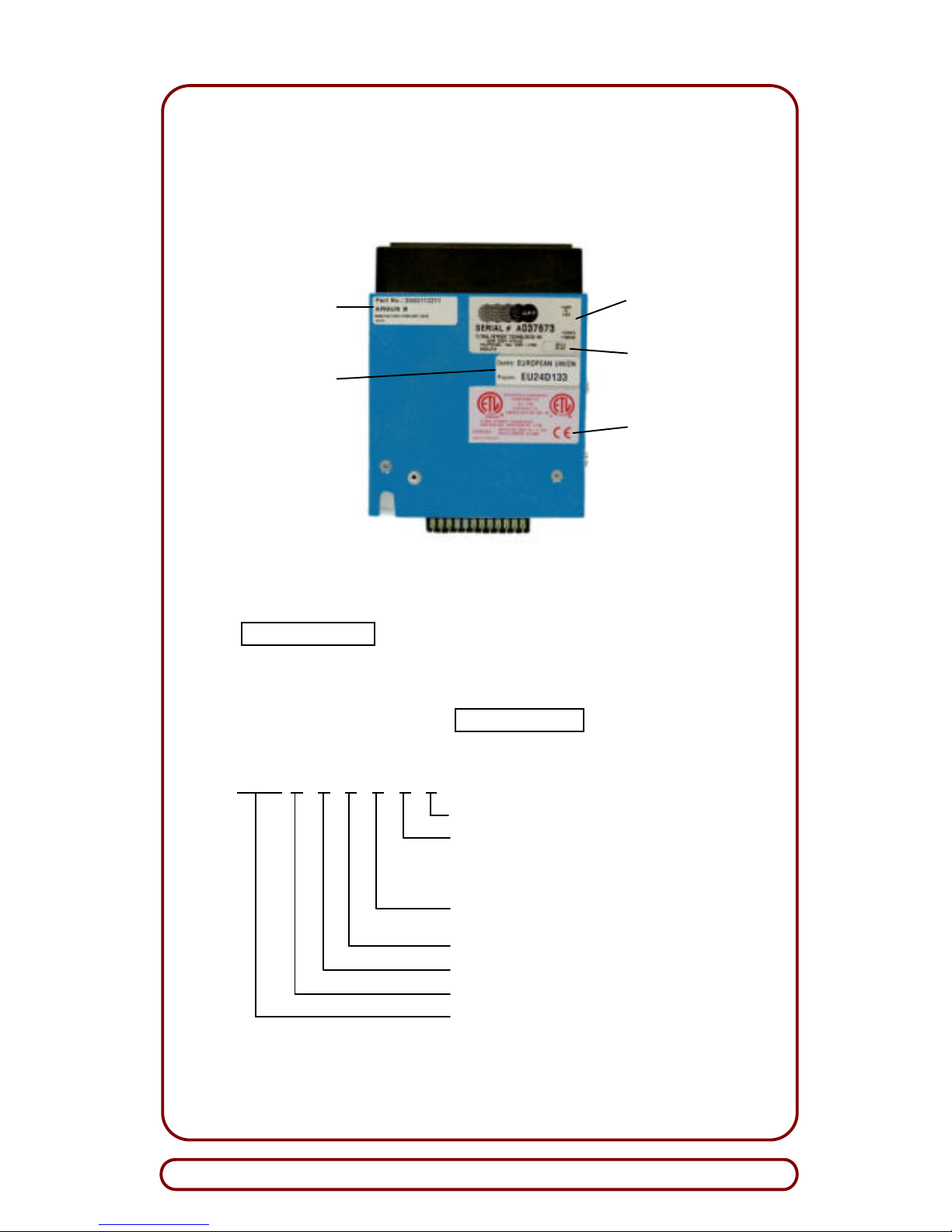
Affixed to the back of SA-4 are five labels (i.e., Part Number, Program,
Serial Number, Origin Country Code, and CE/Warning) that identify
major characteristics of the unit (Figure 3).
Figure 3. Currency Validator Label Identification
The xPart Numberx label contains the date (i.e., month and year)
that the Currency Validator was manufactured. It also contains an alphanumeric code that identifies the version number and the
configurable components (i.e., mechanical and electrical) of the unit.
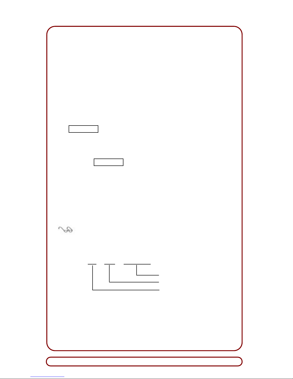
The numbering scheme for the xPart Numberx label is defined below
(Figure 4):
304G X X X X X X
Mounting Pins (1= 4 pins; 2= 2 pins)
Stacker Connector Type
(1= standard AMP; 2= pigtail;
3, 5= stackerless; 4= reverse AMP;
6= outboard/pigtail combo connector)
Bezel Type (1= IDS; 2= IBS; 3= ALI;
4= IBS w/outboard bracket back panel)
Channel Width (1= 70-mm w/inserts; 2= 85-mm)
Main Connector Location (1= side; 2= front)
Input Voltage (1= 24 VDC; 2= 12 VDC)
SA-4 Currency Validator
Figure 4. Part Number Label Numbering Scheme
Serial Number
Label
Origin
Country Code
CE/Warning
Label
Part
Number
Label
Program
Label
Page 10
Global Payment Technologies, Inc.
Page 10 G3M5111
The following is an example of a part number for SA -4:
Sample Part Number: 304G112211
where:
304G indicates SA -4 with common components
1 indicates 24 VDC is required to operate the unit
1 indicates side-mounted main connector
2 indicates 85-mm channel width
2 indicates IBS bezel for back-stack installation
1 indicates STD AMP connector for stacker hookup
1 indicates four mounting pins
The xProgramx label identifies the country and contains an 8-digit alphanumeric code that defines the software characteristics of the
Currency Validator. Two different numbering schemes are used to de-
fine single-country and multi-country databases. The numbering
scheme for a single -country database, shown for the 8-digit number
on the sample xProgramx label, is defined as follows (Figure 5): ?
?? The first two letters represent the ISO country code
?? The next two digits specify the database revision (up to 99,
maximum)
?? The remaining four characters specify the software revision.
The first character of the software revision is a letter that identifies the software type (e.g., network or non-network), and the
next three digits define the software revision number.
Note: If a detailed description of this matrix is required, contact Customer Service (Section 9) for assistance.
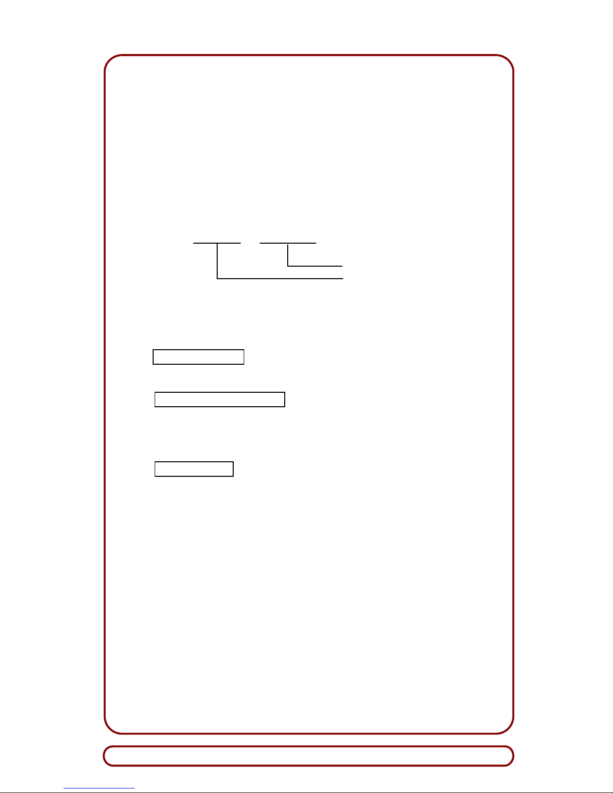
A sample Program Label for single-country databases is defined below:
E U 2 4 D 1 3 3
V2.2; Software Rev is 133
Database Revision is 24
European Union
Figure 5. Program Label Numbering Scheme – Single-Country
Database
Page 11
Installation Guide
G3M5111 Page 11
The num bering scheme for multi-currency databases is defined as follows (see Figure 6):
?? The first four characters of the alphanumeric code define the
database revision (i.e., one letter defines the countries, and
three digits define the database revision).
?? The remaining four characters of the alphanumeric code ide n-
tify the protocol type and the software revision.
A sample Program Label for multi-country databases is defined below:
D 0 0 7 D 1 1 7
V2.2; Revision 117
Germany/Nether; Rev. 7
Figure 6. Program Label Numbering Scheme – Multi-Country
Database
The xSerial Numberx label contains a unique alphanumeric code that
identifies the Currency Validator.
The xOrigin Country Codex mini-label, which is usually affixed on
the Serial Number label, uses a two-letter ISO country code to indicate
the currency database that the Currency Validator was tested and
shipped to.
The xCE/Warningx label indicates the Currency Validator complies
with ETL and CETL requirements, and it specifies the rated input
power (i.e., voltage and current) that is required to safely operate the
unit.
Page 12
Global Payment Technologies, Inc.
Page 12 G3M5111
3.3 Main Connector
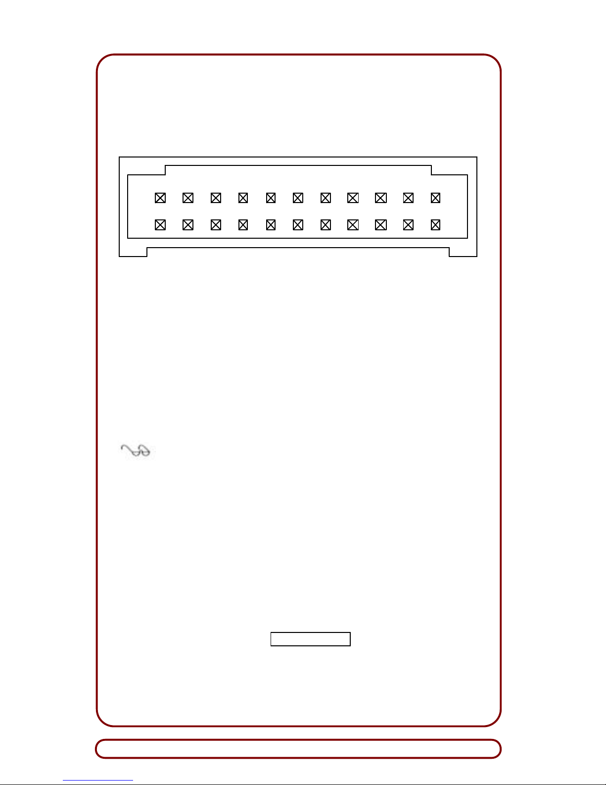
The Main Connector serves as the electrical interface between the
Currency Validator and the Host machine. This 22 -pin connector supplies the power and interface signals (Figure 7) to operate the unit.
1
2
21
22
71113
10
Pin 1: V Sense (note 2) Pin 12: Ground In (note 1)
Pin 2: Ground Pin 13: Ground Out (note 2)
Pin 3: RS-232 RX Pin 14: 15 V (reserved)
Pin 4: RS-232 TX Pin 15: VCC (reserved)
Pin 5: Not connected (reserved) Pin 16: SCL (reserved)
Pin 6: Not connected (reserved) Pin 17: SDA (reserved)
Pin 7: Chassis (note 3) Pin 18: Not connected (reserved)
Pin 8: Ground Pin 19: Not connected (reserved)
Pin 9: Account Number Pin 20: Ground
Pin 10: V In (note 1) Pin 21: Ground
Pin 11: V Out (note 2) Pin 22: Ground Sense (note 2)
Figure 7. Currency Validator 22-Pin Main Connector
Notes to Figure 7:
1. Cable design should connect power to pins 10 and 12
on the Currency Validator.
2. The cable should connect 24 V Sense (Pin 1) to V Out
(Pin 11) and Ground Sense (Pin 22) to Ground Out
(Pin 13). The Currency Validator will not power up if
V Sense and Ground Sense are not connected as
required.
3. Pin 7 is connected directly to the chassis of the
Currency Validator. The chassis is connected to
Ground signals internally to the Currency Validator
through a 0.1-ohm resistance.
A separate, remotely located power supply is required to operate the
Currency Validator. Refer to XCE/WarningX label (Figure 3) for the
rated input power required to safely operate your unit.
Page 13
Installation Guide
G3M5111 Page 13
3.4 Communication Protocols
SA-4 supports serial RS-232 communications which is the interface
standard used with V2.2 protocol supplied by GPT. For information
about using SA-4 with other protocols, contact GPT Customer Service
(Section 9).
When SA-4 requires service, changes to the operational setup can be
made via the 10-position, DIP-Switch package. To obtain the functions
of each switch, refer to the Program Specification Sheet for your software application.
Note: To obtain the Program Specification Sheet for your
unit, contact GPT Customer Service for assistance.
4. INSTALLATION INS TRUCTIONS
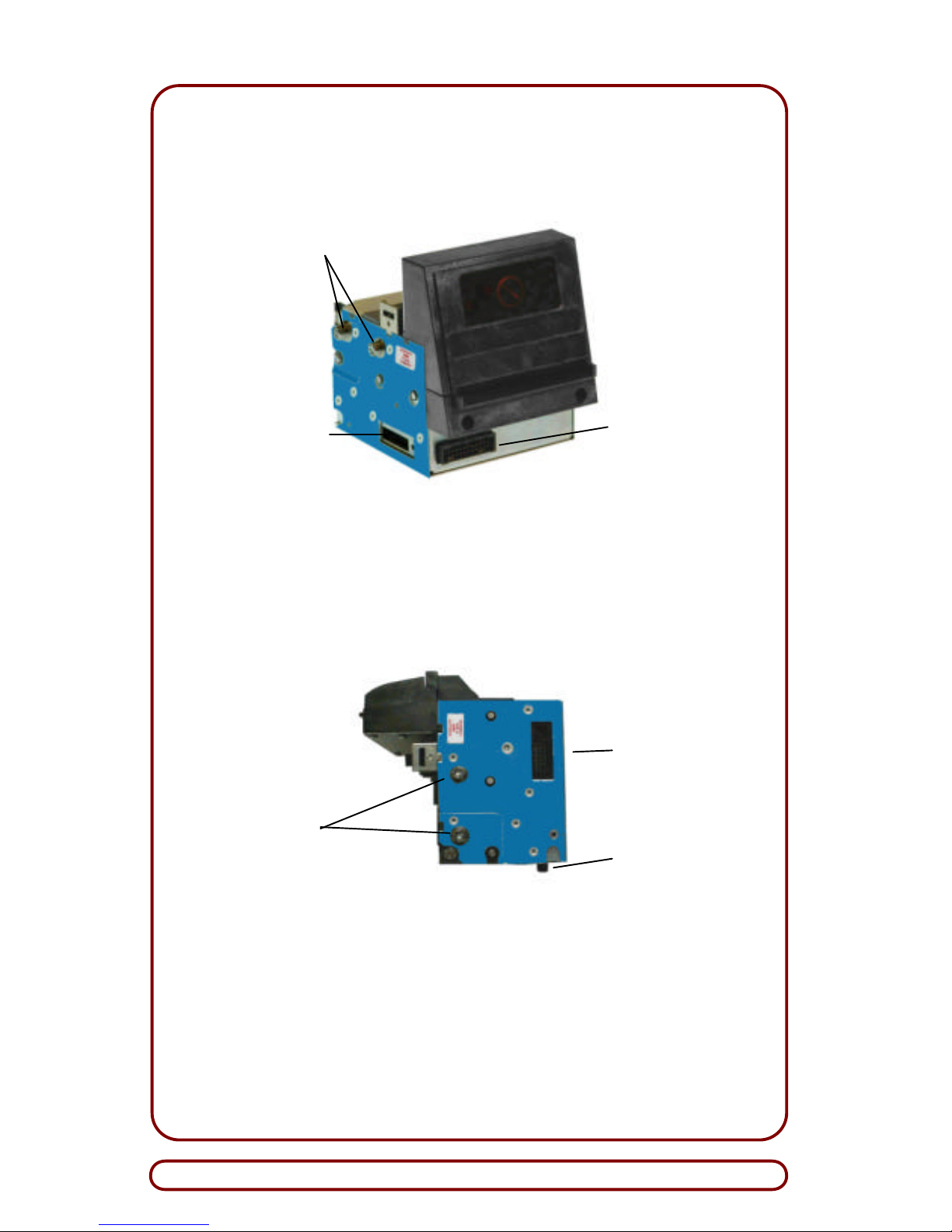
This section describes how to install SA-4 (Figure 8) into a Host ma-
chine. For dimensional drawings of SA-4 down-stack and back-stack
validator heads with stackers, contact Customer Service (Section 9).
WARNING: AVOID PERSONAL INJURY AND/OR DAMAGE
TO EQUIPMENT. DISCONNECT POWER BEFORE
SERVICING THE HOST MACHINE.
4.1 Installation Procedure
To install SA -4, follow these steps:
1. Disconnect electrical power to Host machine.
2. Ensure all DIP switches (Figure 8) are set according to data in
Program Specification Sheet.
3. Using appropriate hardware, secure enclosure (if applicable) to
Host machine.
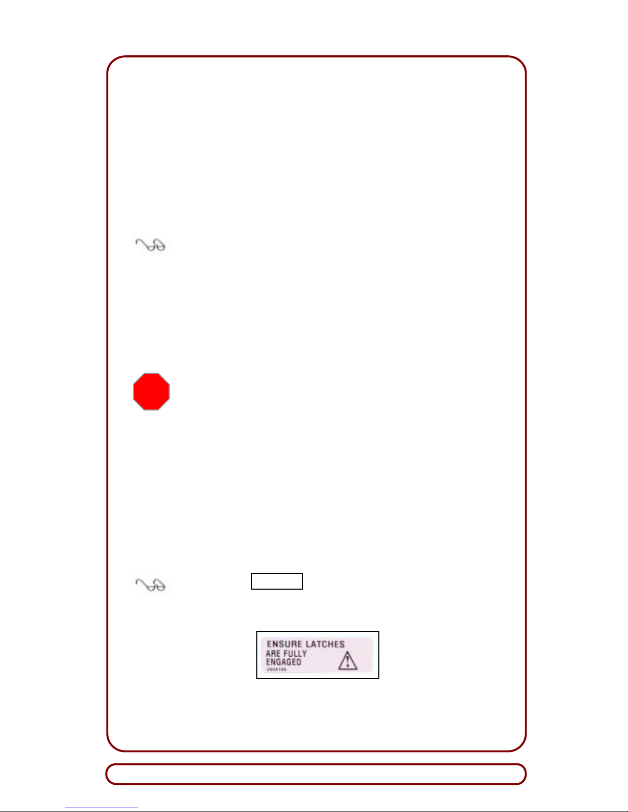
Note: The xCAUTIONx label (show n below), which is
affixed to the Currency Validator, specifies that the latches
should be fully engaged prior to installation.
STOP
Page 14
Global Payment Technologies, Inc.
Page 14 G3M5111
SA-4 Back-Stack Head
(Shown with Front-Mounted Main Connector)
SA-4 Down-Stack Head
(Shown with Side-Mounted Main Connector)
Figure 8. SA-4 Validator Heads – Component Locations
DIP Switches
Mounting
Pins
Main
Connector
Shroud
Socket
Main
Connector
Shroud
Socket
Standard
AMP
Connector
Mounting
Pins
Page 15
Installation Guide
G3M5111 Page 15
!
4. Mount SA-4 into enclosure of Host machine; ensure all mounting
pins are evenly engaged within slots of enclosure.
CAUTION: DO NOT bend the pins on Main Connector
Shroud Socket when attaching Cable Clip. Bent or broken
pins can sever electrical connections and disable the
Currency Validator.
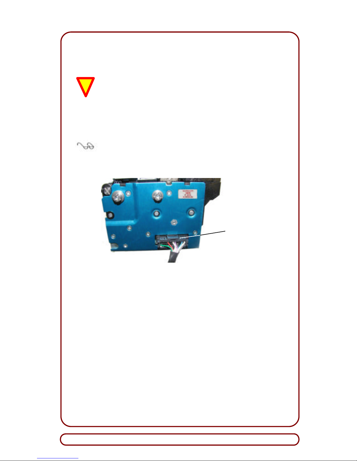
5. Carefully attach Cable Connector to 22-pin, Main Connector
Shroud Socket on SA -4 (Figure 9).
Note: Ensure Locking Tab on Cable Connector is properly
oriented before attaching it to Main Connector. When properly
installed, the Locking Tab should snap into place such that it
cannot slide out of Main Connector.
Side-Mounted Main Connector
Figure 9. Attaching Cable Connector to Main Connector
6. Connect appropriate interface-harness cable from Host controller
to Main Connector Cable.
7. Carefully place all cables to avoid interference with equipment
operation.
8. Mount Security Removable Cassette into enclosure and engage it
to blind-mate connector (i.e., inboard AMP configuration) on
SA-4; if pigtail connector is used, connect it to stacker.
Locking Tab
Page 16
Global Payment Technologies, Inc.
Page 16 G3M5111
WARNING: PERSONAL INJURY AND/OR DAMAGE TO
EQUIPMENT MAY RESULT BY APPLYING INCORRECT
VOLTAGE TO THE CURRENCY VALIDATOR. ONLY APPLY
VOLTAGE AS SPECIFIED ON xCE/WARNINGx LABEL
(Figure 3).
9. Apply power to Host machine.
Note: On the bezel, observe that each pair of green LEDs are
flashing sequentially at 4 Hertz. If LEDs are not flashing, or red
LED is lit, proceed to Troubleshooting (Section 6).
10. Proceed to Video-Level Adjustment (Section 8).
STOP
Page 17
Installation Guide
G3M5111 Page 17
5. BEZEL LED DISPLA YS
The LED patterns on the bezel of Currency Validator allow service
personnel to view and evaluate equipment operation. This section
provides sample bezel displays that represent program med patterns
for V2.2 protocol.
Various display patterns indicate the stages of the bill verification
process and denote when an equipment malfunction has occurred. On
power-up, the Currency Validator performs a self-test routine. If the
unit is operational, the bezel will show a runway light pattern (i.e., Idle
State). However, if a malfunction is detected, a self-diagnostic error
display will occur as described in Subsection 5.2.
Note: Performance data, detailed and historical, is available
through RS-232 communication and/or the Soft-Drop Analyzer.
For details about the software diagnostics package available
from GPT, contact Customer Service (Section 9).
5.1 Displays for Normal Equipment Operation
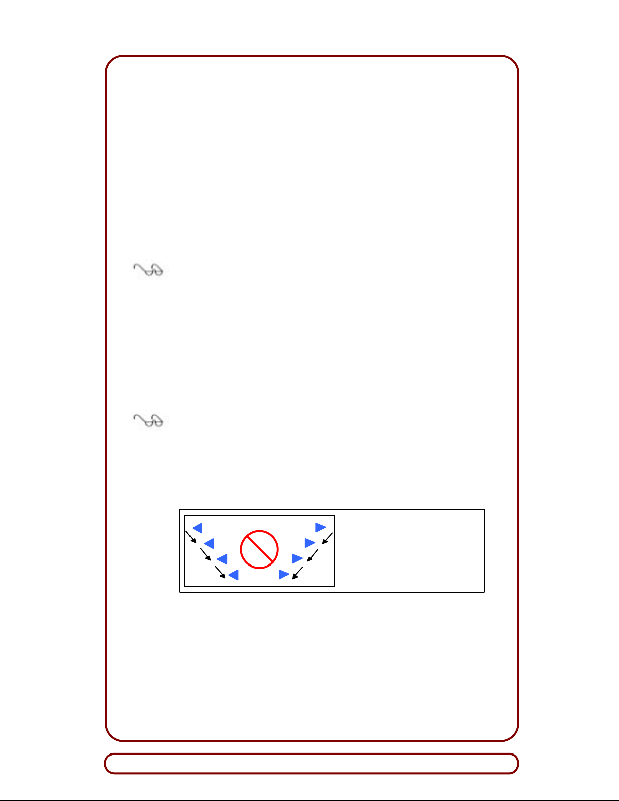
As the bill moves through the currency channel, light patterns that appear on the bezel identify the current state of the unit. Shown below
are light patterns and their associated Currency Validator states for
normal equipment operation.
Note: The lit, green LEDs are represented by the solid,
triangular-shaped symbols.
?? Idle State:
The Currency Validator is operational and ready to accept a
bill.
Idle State:
Each
pair of green LEDs
sequentially flash at 4 Hz.
The red, center LED is not
lit.
Page 18
Global Payment Technologies, Inc.
Page 18 G3M5111
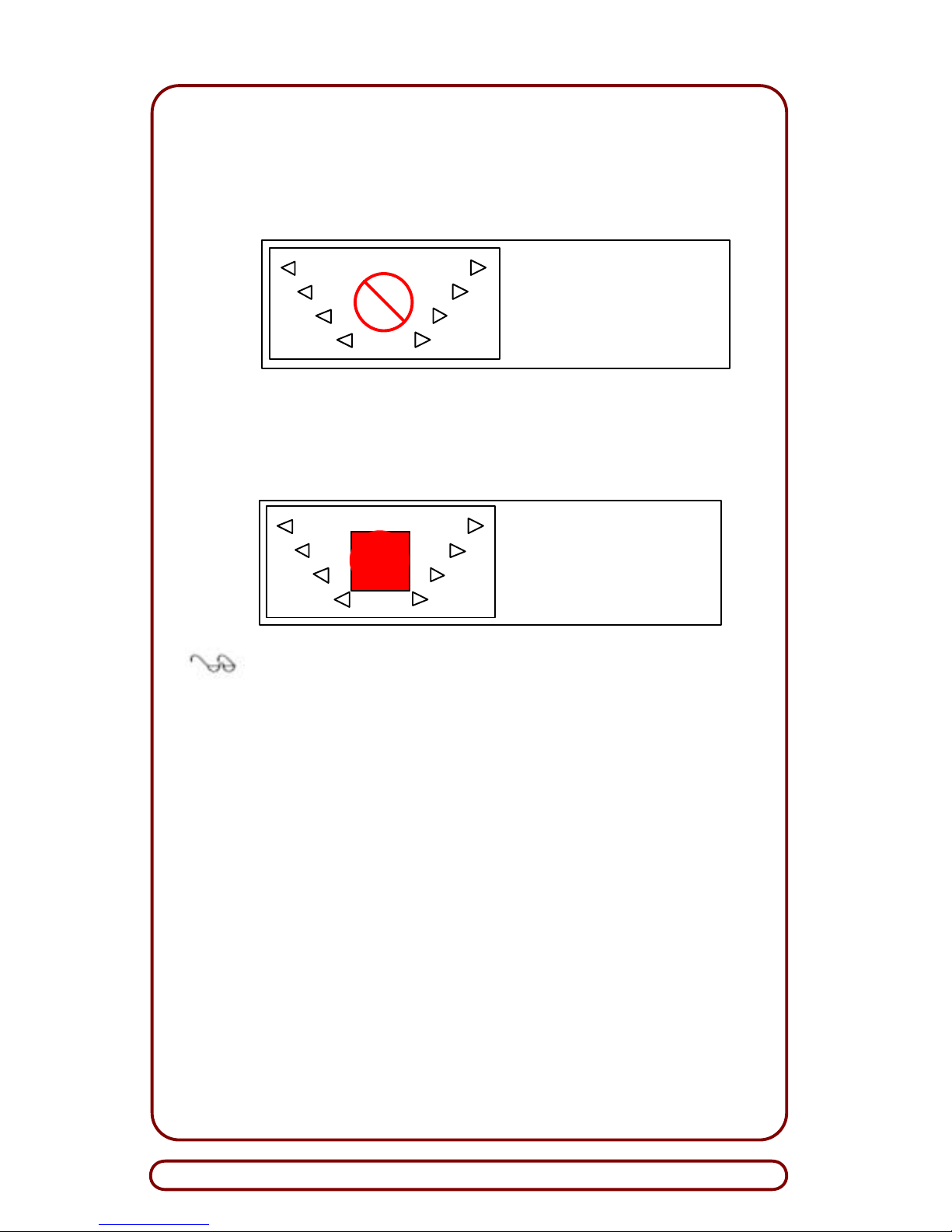
?? Accepting State:
A bill is inserted into the Currency Validator. The front sensor
is activated, and the unit is accepting data and evaluating the
bill to determine if it is valid.
?? Escrow State, Stacking State, and Rejecting State:
When the Currency Validator enters the Escrow State, the
Stacking State, or the Rejecting State, the light pattern
shown below appears.
Escrow, Stacking or
Rejecting State:
Green LEDs are not lit.
The red LED is lit.
Note: If an equipment malfunction occurs, the Currency
Validator will not accept the bill (Subsection 5.2 ).
Accepting State:
All green LEDs are not lit.
The red LED is not lit.
Page 19
Installation Guide
G3M5111 Page 19
5.2 Self-Diagnostic Error Displays
Besides the light patterns in Subsection 5.1, the Currency Validator
provides self -diagnostic error displays when an equipment malfunction
occurs. The most common types of errors appear below. For corrective actions, refer to Troubleshooting (Section 6).
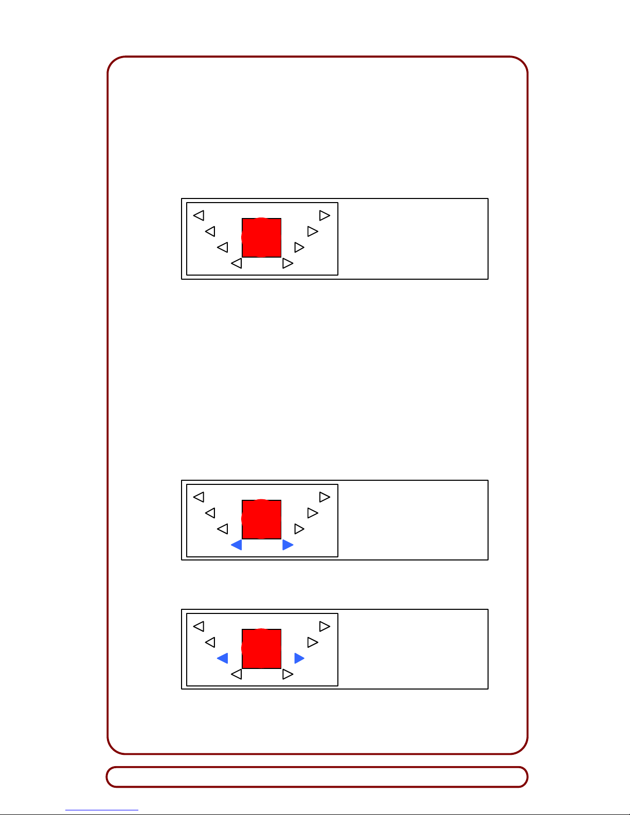
?? Any one of the following conditions can cause this display:
Error – Malfunction:
Green LEDs are not lit.
If front sensor is active,
the red LED is lit.
(1) A bill is inserted in the channel but does not advance into
the channel.
(2) Stacker is not connected to the Currency Validator and
Stacker Required Mode is enabled.
(3) The Currency Validator is operational but has been inhibited (i.e., Inhibit State) from accepting bill s. This condition can
be caused by an inhibit command issued by the controller or
a communication failure between the equi pment.
?? Bill jams in the channel – middle sensor is covered.
Error – Currency Validator:
If front sensor is active, fourth
row of green LEDs are lit and
red LED is lit; if front sensor is
not active, all LEDs are not lit.
?? Stacker is jammed or full.
Error – Stacker Jammed:
Third row of green LEDs
are lit, and red LED is lit.
Page 20
Global Payment Technologies, Inc.
Page 20 G3M5111
6. TROUBLESHOOTING
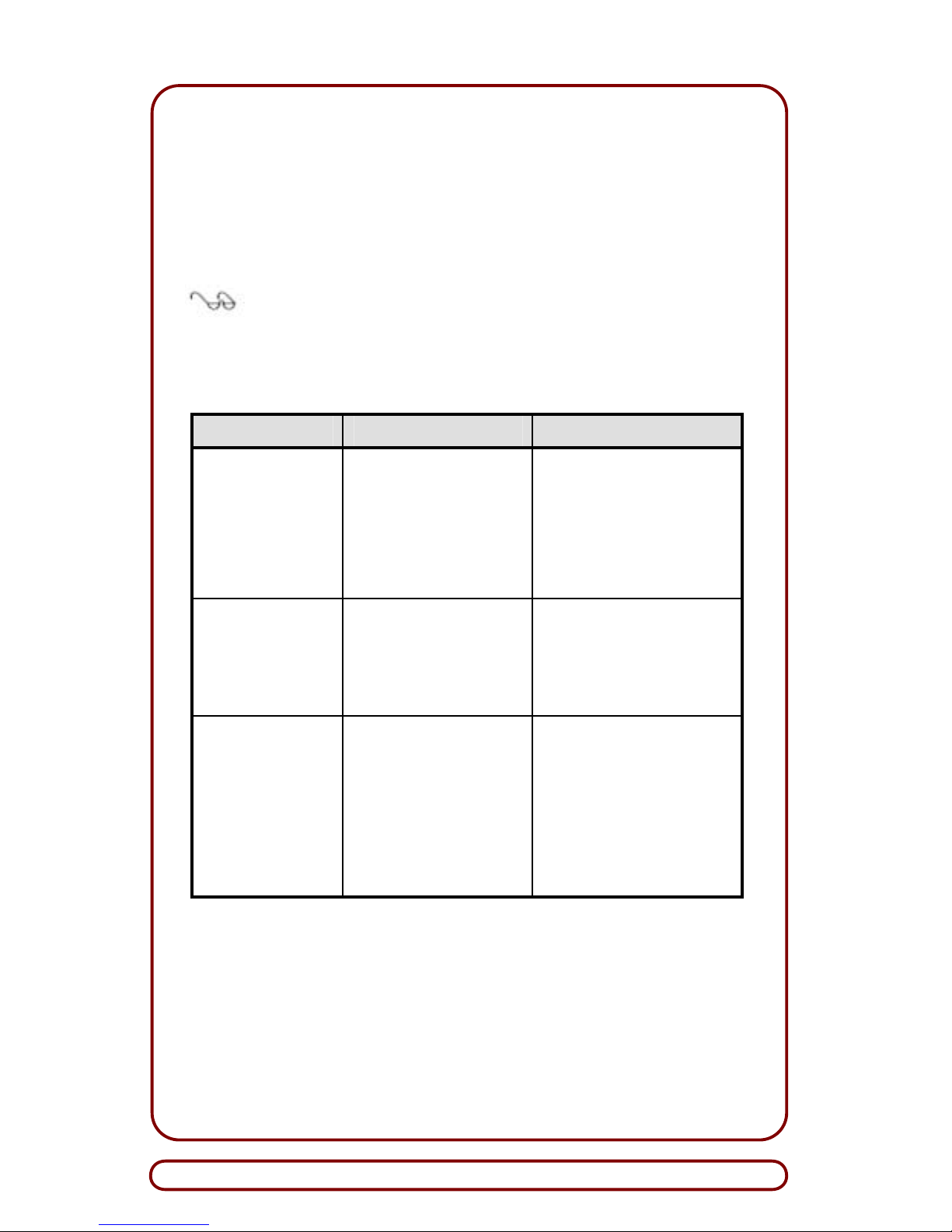
The possible causes and corrective actions for malfunctions associated with Currency Validator (Table 1) and stacker (Table 2) appear
in this section. If corrective action fails to resolve the problem, contact
Customer Service (Section 9). Should the unit require cleaning, refer
to Periodic Cleaning (Section 7).
Note: Repair of the Currency Validator is restricted to
corrective actions in Table 1. Unauthorized repair, as
indicated by broken Tamper-Evident Seals, will void the
warranty.
Table 1. Currency Validator Troubleshooting Chart
Symptom Possible Causes Corrective Actions
Currency Validator is
not working; bezel
LEDs are not lit.
External power or GND is
not applied to Currency
Validator.
Verify that power and ground
are connected to appropriate
pins on Main Connector (Fig-
ure 7).
Damaged connector and/or
pins on Main Connector.
Check for bent, missing or
damaged pins on Main Connector.
At power up, stepper
motor turns five times
and then stops.
Front and/or rear optical
sensors are blocked, dirty,
or damaged.
Clean front and rear optical
sensors, and check that sensors are not blocked or
physically damaged.
Perform VLA (Section 8).
Bills continually jam in
channel.
Foreign object(s) is in channel.
Remove foreign objects from
channel; ensure channel is free
of all debris.
Pressure rollers are dirty,
damaged or loose.
Clean pressure rollers; check
pressure rollers for proper tension.
Drive belts are damaged. Replace drive belts and check
for proper tension.
Page 21
Installation Guide
G3M5111 Page 21
Table 2. Stacker Troubleshooting Chart
Symptom Possible Causes Corrective Actions
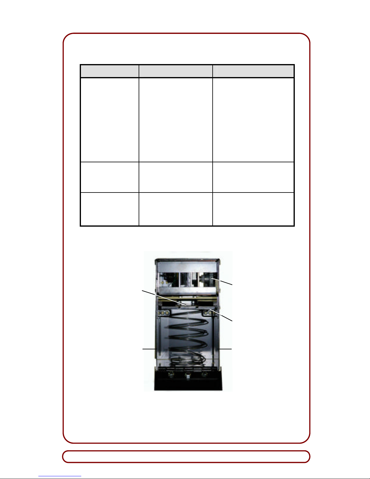
Stacker malfunctions. Stacker entry slot is blocked
by Pusher Plate (Figure 10).
Check Stacker's entry slot for
possible damage and/or blockage. Also, check slide guide for
damage.
Foreign object jamming
drive gears.
Remove foreign object from
drive gears.
Stacker may be full or cur-
rency slot is blocked.
Empty Stacker. Also, lubricate
Stacker components per instructions in Technical Bulletin
GPB2T11 (latest revision).
Bills jam in Stacker. Dirty bill guides or foreign
objects in Stacker.
Clean bill guides; remove foreign objects.
Stacker may be full. Empty Stacker.
Currency Validator
reports a Stacker jam
but bill is not jammed
in Stacker.
Pusher Plate Sensor is
damaged, and it does not allow Pusher Plate to return to
top-most position.
Replace Stacker.
Figure 10. Universal SRC – Back View of Internal Parts
Pusher Plate
Pressure Plate
Slide Guide
Drive Gears
Pressure Plate
Pressure Plate
Slide Guide
Page 22
Global Payment Technologies, Inc.
Page 22 G3M5111
!
7. PERIODIC CLEANING
Depending on its environment and amount of use, SA-4 may require
periodic cleaning to restore it to optimum performance. Under normal
use, SA-4 should be cleaned every 6 to 12 months. For unusual operating conditions, such as when the unit is exposed to dirt, dust, water
spray, airborne oil, and/or sand, more frequent cleaning will be required.
7.1 Cleaning the Bezel
To remove dirty deposits and smudges from the bezel and other surfaces of SA-4, use a soft, lint-free cloth, dampened with a 90-percent
solution of isopropyl alcohol only.
CAUTION: DO NOT flood the bezel area with alcohol, as
this can damage the electronics integrated within the bezel.
7.2 Cleaning the Currency Channel
With constant use, a buildup of dirt, which is transferred from the surface of the currency, will accumulate on the pressure rollers, magnetic
head, and optics. Periodically, these items should be cleaned to ensure reliable operation.
7.2.1 Required Items
The following items are required to clean SA -4:
?? Soft, lint -free cloth
?? Isopropyl alcohol (90-percent solution).
7.2.2 Procedure
To clean the currency channel, follow these steps:
WARNINGS:
1. AVOID PERSONAL INJURY AND/OR SEVERE
DAMAGE TO THE VALIDATOR. DISCONNECT POWER
SUPPLY BEFORE CLEANING OR PERFORMING
MAINTENANCE ON VALIDATOR.
2. REDUCE AND/OR PREVENT RISK OF ELECTRIC
SHOCK. DO NOT CLEAN OR REPAIR THE VALIDATOR
IN A DAMP OR WET ENVIRONMENT.
3. AVOID DANGEROUS SITUATIONS. DO NOT
INTRODUCE FLAMMABLE LIQUIDS OR GASES TO
MAINTENANCE WORK AREA WHEN CLEANING OR
PERFORMING MAINTENANCE ON CURRENCY
VALIDATOR.
STOP
Page 23
Installation Guide
G3M5111 Page 23
!
1. Power-down SA-4; disconnect Main Connector Cable from 22-pin
Main Connector Shroud Socket of SA-4.
2. Remove SA -4 from its mounting frame.
CAUTIONS:
1. DO NOT scratch the surfaces of the optics windows or
the magnetic head while cleaning these devices, as this
can impair the validator's performance.
2. DO NOT allow liquids to contact the drive belts or enter
the unit, as this can damage components.
3. DO NOT use unapproved cleaners; unapproved
cleaners may cause permanent surface damage. Use only
cleaners as directed in this procedure.
4. DO NOT use cotton swabs to clean the unit as this can
leave unwanted material on the surfaces.
5. DO NOT exceed 90 degrees when opening the UpperGuide Assembly or damage to wiring can occur.
3. Access currency channel by releasing spring-loaded latches; partially open Upper-Guide Assembly – DO NOT exceed 90 degrees
– to expose currency channel with its optical system and magnetic head.
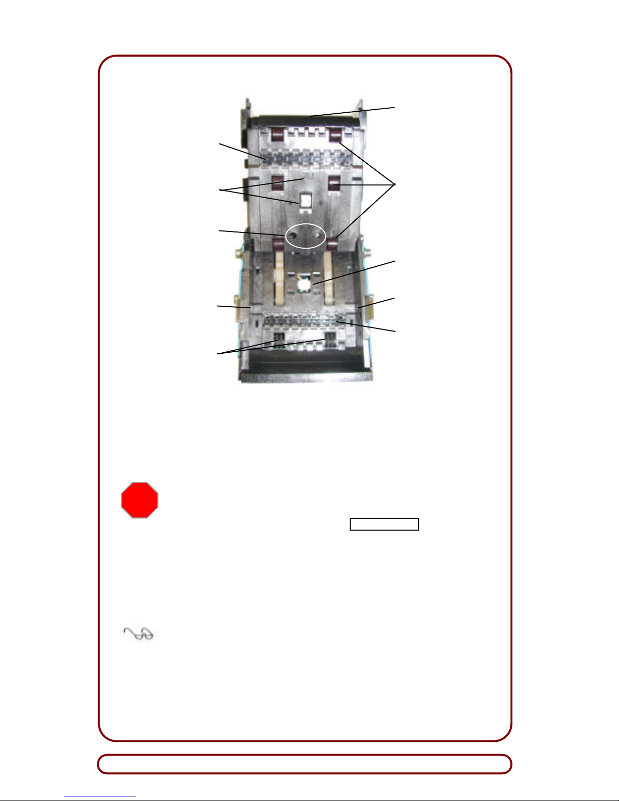
4. Using a soft, lint-free cloth dampened with 90 -percent is opropyl
alcohol, clean the following areas (Figure 11):
a. Currency channel surfaces: remove surface dirt on both up-
per and lower guides.
b. Optics window area: clean all surfaces (top and bottom).
c. Bar Code Reader and Mag head: carefully remove deposits
from surface areas; DO NOT scratch surface area.
d. Pressure Ro llers: clean all surfaces.
e. Front-Drive Axle with O-Rings: clean all surfaces.
f. Front and Rear Optical Sensors: clean all surfaces.
g. Side-looking sensors: clean all surfaces.
5. Swing Upper-Guide Assembly to its closed (locked) position, and
verify that spring-loaded latches are fully engaged.
Page 24
Global Payment Technologies, Inc.
Page 24 G3M5111
Figure 11. Currency Channel – Cleaning Surfaces for SA-4
Down-Stack Unit
6. Mount SA-4 into enclosure of Host machine.
WARNING: PERSONAL INJURY AND/OR DAMAGE TO
EQUIPMENT MAY RESULT BY APPLYING INCORRECT
VOLTAGE TO THE CURRENCY VALIDATOR. ONLY APPLY
VOLTAGE AS SPECIFIED ON XCE/WARNINGXXLABEL
(Figure 3).
7. Connect Main Connector Cable from Host controller to 22-pin
Main Connector Shroud Socket on SA -4.
8. Apply power and close door of Host machine.
Note: On the bezel, observe that each pair of green LEDs are
flashing sequentially at 4 Hertz. If LEDs are not flashing or the
red LED is lit, proceed to Troubleshooting (Section 6).
9. The Currency Validator is operational and ready to accept currency.
Front Optical
Sensors
(not shown)
Pressure Rollers
(6, Total)
Mag Head Roller
Side-Looking
Sensor
Optics Window
Optics Window
Bar Code Reader/
Mag Head
Rear Optical
Sensors
Side-Looking
Sensor
Front-Drive Axle
with O-Rings
STOP
Page 25
Installation Guide
G3M5111 Page 25
!
8. VIDEO -LEVEL ADJUSTMENT
The Video-Level Adjustment (VLA) is used to optimize the performance of the Currency Validator. Using an ARGUS-specific VLA card
only, the service technician can calibrate the optical sensing circuitry
to its optimal levels. This can be do ne in the gaming machine or at the
workbench with just a power source.
This procedure is applicable to all SA-4 Currency Validators and must
be performed under the following conditions:
?? At final installation of the gaming machine, prior to public use
(this includes retrofitting Currency Validators into gaming machines at the casino or operator site).
?? After the unit is reconfigured to accept a different size cur-
rency (e.g., when the width of the currency channel is
changed).
?? After preventive maintenance.
?? Whenever bank note acceptance is degraded.
8.1 Required Items
The items required to perform the VLA are:
?? Applicable Program Specification Sheet
CAUTION: ONLY USE the correct VLA card, as indicated in
your Program Specification Sheet, when doing a VLA. Using the
wrong VLA card can cause impaired Currency Validator
performance.
?? VLA Card for 70-mm wide channel (GPT PN 300EO005); or,
?? VLA Card for 85-mm wide channel (GPT PN 300EO019)
?? Small DIP -switch manipulator (e.g., a small, non-metallic, non-
conductive stick-like item such as a toothpick or plastic tweezers).
Page 26
Global Payment Technologies, Inc.
Page 26 G3M5111
!
8.2 Procedure
To perform VLA, follow these steps:
1. Power-down Currency Validator.
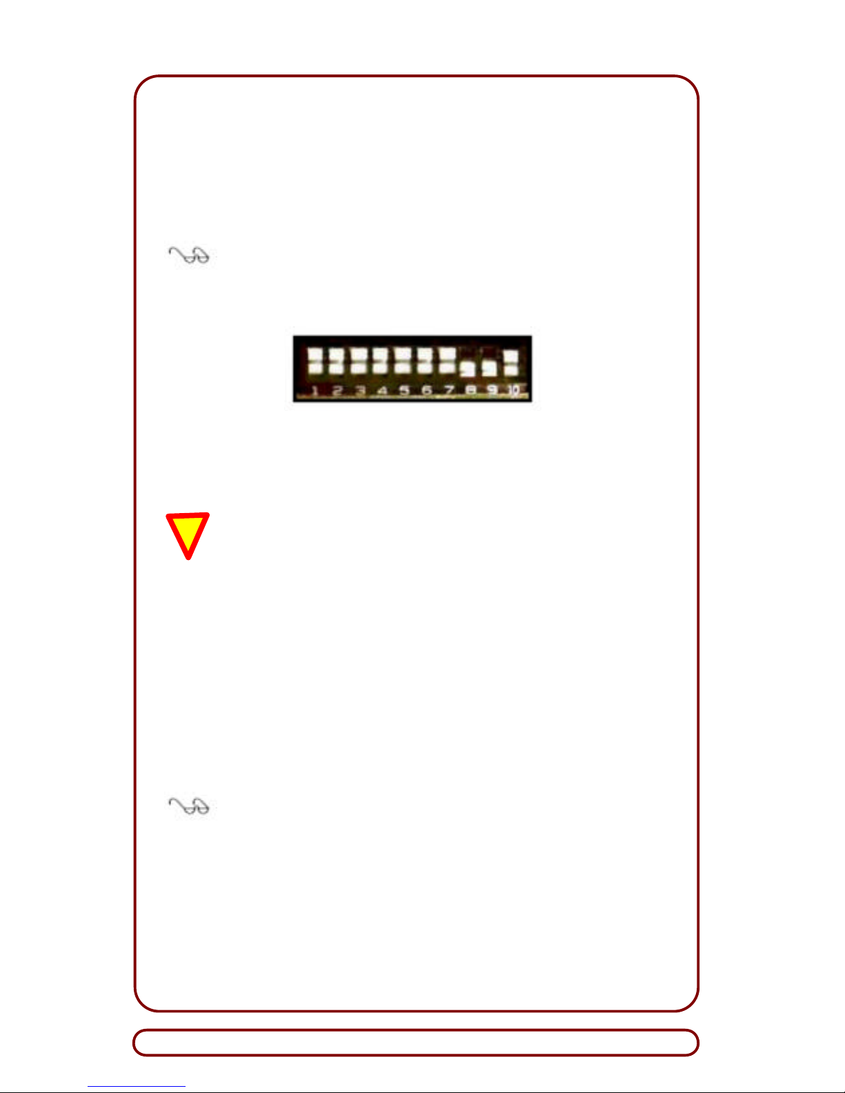
2. Set DIP-Switches 8 and 9 to on position (i.e., move switch toward
number) (Figure 12).
Note: DIP-Switches 8 and 9 are used for servicing the
Currency Validator. All other DIP Switches are set to the
specific application Program Specification Sheet for your
unit and SHOULD NOT be changed.
Figure 12. 10-Pack DIP-Switch Package
3. Power-up Currency Validator.
CAUTION: DO NOT use cut, torn, creased, folded or
perforated VLA cards for this test. Damaged cards can
skew the VLA; damaged cards should be discarded and
replaced with new cards.
4. Insert VLA Card.
The VLA Card will be drawn into the Currency Validator. If the in-
ternal temperature of Currency Validator is between 25°C and
60°C, the red LED will illuminate and stay on, indicating that VLA
is being performed. When the temperature is outside the range of
25°C and 60°C, the red LED will flash; the Currency Validator will
wait, up to 5 minutes, for the temperature to be within the range
previously specified, and then it will pr oceed with VLA.
Note: The VLA card should be stored on a flat surface to
prevent damage (e.g., creases and folds) to the card.
5. Power-down Currency Validator.
6. Set DIP-Switches 8 and 9 to off position (i.e., move switch away
from number), then set other switches as specified by applicable
Program Specification Sheet for your software configuration.
Page 27

Installation Guide
G3M5111 Page 27
8.3 Description of VLA Process
During the VLA process, the Main Optical Sensors and the SideLooking Sensors (SLS) are adjusted. Before the card is inserted during the VLA, the Currency Validator will adjust the SLS. This part of
the process starts when the Red Status LED is illuminated and remains on for approximately one-quarter (0.25) second. When the
Status LED goes off, the SLS adjustment process is underway. This
can occur from one to five seconds, but typically is performed in about
one second. At the end of the SLS adjustment, the Sta tus LED will either:
1. Illuminate and remain on, indicating the SLS adjustment completed successfully, the settings were stored in non-volatile
memory, and the Currency Validator is ready to accept the VLA
card for Main Optical Sensor adjustment, or
2. Blink rapidly three times repeatedly, indicating that the SLS adjustment failed. Should the adjustment fail, the Currency Validator
will not accept the VLA card to finish the adjustment process.
While the VLA card is in the Currency Validator, the brightness of the
emitters and the sensitivities of the detectors are adjusted. If a problem occurs during the adjustment (i.e., inability to adjust co rrectly), the
Currency Validator will eject the VLA card and the Status LED will
blink ra pidly three times (repeatedly) to indicate the failure. However, if
the adjustment is successful, the settings will be stored in non -volatile
memory.
8.4 Precautions
The quality of the VLA card will affect the quality of the adjustment.
When not in use, the card should be kept in an envelope and stored in
a cool, dry environment. If the card becomes soiled or physically damaged (e.g., creased, perforated, bent, etc.), replace it with a new one.
Page 28
Global Payment Technologies, Inc.
Page 28 G3M5111
9. REQUESTING SERVICE
When calling for service, have the following information ready so that
a GPT Customer Service associate can quickly assist you. Refer to
the Company Directory (Subsection 9.1 ) for the nearest GPT Service
Center in your area.
?? Serial number (Figure 3)
?? Part number (Figures 3 and 4)
?? Program revision number (Figures 3 and 5 or Figures 3
and 6)
?? Self-Diagnostic Error Displays (Subsection 6.2) or a descrip-
tion of the problem.
9.1 Company Directory
Global Payment Technologies, Inc.
General Information: 1-800-472-2506
E-Mail Addresses:
Sales Information................[email protected]
Customer Service ................[email protected]
Global Payment Technologies, Inc.
Corporate Headquarters
425-B Oser Avenue
Hauppauge, New York 11788-3640
USA
Tel : +(631) 231-1177 or 1-800-472-2506
Fax : +(631) 434-1771
Global Payment Technologies, Ltd.
Europe
29 Park Royal Metro Centre
Britannia Way, London NW10 7PA
Tel : +(44) 20 8961-6116
Fax : +(44) 20 8961-6117
Page 29
Installation Guide
G3M5111 Page 29
9.1 Company Directory (Continued)
Global Payment Technologies
Australia, (Pty.) Ltd.
13-15 Lyon Park Road
Macquarie Park, NSW 2113
Australia
Tel : +(612) 9887-8600
Fax : +(612) 9887-8601
Global Payment Technologies Holdings (Pty.) Ltd.
South Africa
31 Impala Road
Chiselhursten, Sandton 2196
South Africa
Tel : +(27) (11) 217-4600
Fax : +(27) (11) 783-9549
GPT Russia & CIS
Russia, 127030 Moscow
Sushchevskaya 21, Office 31
Tel/Fax: +7 095 973 5760
Tel: +7 095 973 5761
Notes:
Page 30
Global Payment Technologies, Inc.
Page 30 G3M5111
Warranty Notice:
SA-4
Currency Validators
Important!
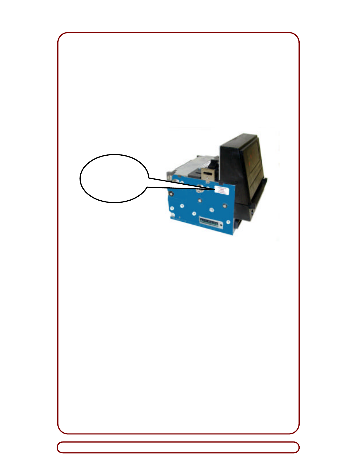
On the Currency Validator, Tamper-Evident Seals have
been placed at two locations (see photo above). If these
seals are removed or broken, the GPT Warranty, described
in this guide, will be voided.
Global Payment Technologies, Inc., (GPT) provides a Warranty
to the purchaser of the SA-4 Currency Validator. Unless otherwise authorized, and agreed to in writing by GPT, repair of the
Currency Validator is restricted to GPT-trained and authorized
service personnel only. The procedures within this guide do not
void the warranty. However, unauthorized repair, as indicated
by broken Tamper -Evident Seals, will void the warranty.
WARRANTY
VOID
IF SEAL
IS BROKEN
Page 31

Installation Guide
G3M5111 Page 31
GLOBAL PAYMENT TECHNOL OGIES, INC.
LIMITED WARRANTY PROVISION
Global Payment Technologies, Inc. (GPT) extends the following lim-
ited warranty to the purchaser (Purchaser) of GPT products
(Products). Unless otherwise authorized and agreed to in writing by
GPT, all Products are guaranteed to be free of defects in material and
workmanship for the period outlined in the Product Line Warranty table noted below. GPT agrees to repair or replace, without charge
during the applicable warranty period, any unit which proves to be defective upon examination by GPT or its licensed affiliates, provided
that such unit is accompanied by proof of purchase satisfactory to
GPT. Any and all associated risks and costs of shipping, including, but
not limited to, any applicable duties and tariffs, for an allegedly defe ctive unit to or from the offices of GPT or its licensed affiliates shall be
borne by the Purchaser.
This warranty applies only if all parts of the Products have been properly serviced according to the applicable product manual, and
provided the alleged defective part, upon examination by GPT or its licensed affiliates, in their sole determination, shall prove to be
defective. This warranty will not apply to any of the Products in which
the electronic PCB assemblies, or any other part, has been subject to
any modification, accident, abuse, or misuse. Determination of such
modification, accident, abuse or misuse will be solely at the discretion
of GPT or its licensed affiliates.
GPT grants Purchaser a limited, nonexclusive and nontransferable license to use the software provided with the Product (Software). GPT
shall take commercially reasonable efforts to create Software databases that will not accept any type of fraudulent or counterfeit notes.
Additionally, GPT shall, from time to time, update the Software to
eliminate the acceptance of fraudulent or counterfeit notes (Updates).
However, GPT cannot and does not warrant or accept any liability that
such notes will not be accepted at any time while using the Product,
Software and/or the Updates. The Updates shall come with the same
license terms as the Software, and shall be offered to Purchaser at a
cost to be determin ed by GPT. Both the Software and Updates are
provided "AS IS" and GPT shall at all times retain title to the Software
and Updates, including any and all copies, regardless of the form or
media, and to all copyrights and intellectual property rights applicable
therein.
Page 32
Global Payment Technologies, Inc.
Innovative Ideas . . . Global Acce
p
tance
THIS WARRANTY SHALL BE IN LIEU OF ANY OTHER WARRANTY,
EXPRESS OR IMPLIED, INCLUDING BUT NOT LIMITED TO, ANY
IMPLIED WARRANTIES OF MERCHANTABILITY, TITLE, NONINFRINGEMENT AND FITNESS FOR A PARTICULAR PURPOSE.
THERE ARE NO OTHER WARRANTIES, INCLUDING BUT NOT
LIMITED TO, ANY IMPLIED WARRANTIES OF MERCHANTABILITY,
TITLE, NON -INFRINGEMENT AND FITNESS FOR A PARTICULAR
PURPOSE, WHICH EXTEND BEYOND WHAT IS DESCRIBED
HEREIN UNLESS AUTHORIZED IN WRITING BY GPT. IF THIS
PRODUCT DOES NOT PERFORM AS WARRANTED HEREIN,
PURCHASER'S SOLE REMEDY SHALL BE REPAIR OR REPLACEMENT OF THE PRODUCT, AT GPT'S OPTION. IN NO
EVENT WILL GPT BE LIABLE FOR ANY INDIRECT, SPECIAL, INCIDENTAL, EXEMPLARY OR CONSEQUENTIAL DAMAGES
(INCLUDING, BUT NOT LIMITED TO, DAMAGES FOR LOST
REVENUE, LOST WAGES, LOST SAVINGS OR LITIGATION) ARISING FROM THE PURCHASE, USE OR INABILITY TO USE THIS
PRODUCT AND/OR THE SOFTWARE, EVEN IF GPT HAS BEEN
ADVISED OF THE POSSIBILITY OF SUCH DAMAGES.
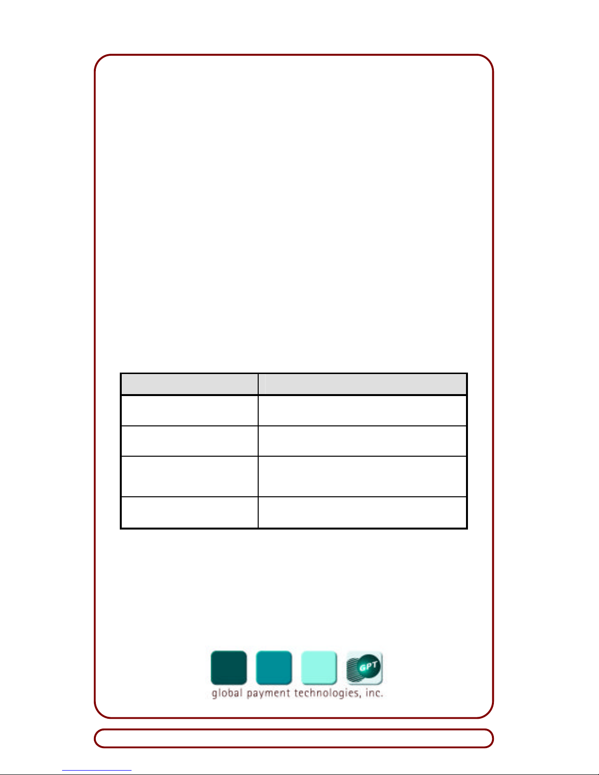
Product Line Warranty Table
Product Line Warranty Period
SA-4 Currency Validators 18 months parts and labor; 24 months parts from the
date of shipment of goods from GPT's factory.
Security Removable Cassettes
(SRC)
One (1) year parts and labor from the date of shipment of goods from GPT's factory.
Repaired Products (In-Warranty) 90 days or the remainder of the standard warranty
period, whichever is longer. This period is from the
date of shipment of goods from GPT's factory.
Repaired Products (Out-ofWarranty)
90 days from the date of shipment of goods from
GPT's factory.
 Loading...