

Page 1

Multi-Radio-Modem
X3000
Installation and Configuration Guide
Page 2

Important Notice
The Multi-Radio-Modem X3000 (MRM-X3000) when used in conjunction with a third
party wireless data device (Express card or USB radio device) on a well-designed
wireless network is intended to provide secure reliable communications.
GNCI accepts no responsibility for damages of any kind resulting from network failure,
instability of a wireless network, incorrectly configured MRM devices, or failure of the
GNCI MRM-X3000 device.
Copyright
©2003, 2004, 2005, 2006, 2007, 2008, 2009, 2010, 2011, 2012, 2013, Global Net
Commerce Inc. All rights reserved.
Printed in Canada
No part of this publication may be reproduced, stored in a retrieval system, or
transmitted by any form or by any means, without the prior permission of the publisher.
The information in this manual is subject to change without notice.
Global Net Commerce Inc. shall not be liable for incidental or consequential damages
resulting from the use, performance, or furnishing of this manual.
Trademarks
Product names, brands, logos, trademarks, etc., other than those of Global Net
Commerce Inc. used in this manual, are owned by their respective companies.
The equipment certifications appropriate to your devices are marked on the device and
the accompanying product specific documentation.
Devices inserted into the Express Card or USB slot of the Multi-Radio-Modem have
their own regulatory compliance markings and documentation.
Important Note: United States FCC Information
This equipment has been tested and found to comply with the limits for a class B digital
device, pursuant to part 15 of the FCC rules and ICES 03. These limits are designed to
provide reasonable protection against harmful interference in a residential installation.
This equipment generates uses and can radiate radio frequency energy and, if not
installed and used in accordance with the instructions, may cause harmful interference
to radio communications. However, there is no guarantee that interference will not occur
Regulatory Information
Page 3

in a particular installation. If this equipment does cause harmful interference to radio or
television reception, which can be determined by turning the equipment off and on, the
user is encouraged to try to correct the interference by one or more of the following
measures:
Reorient or relocate the receiving antenna.
Increase the separation between the equipment and the receiver.
Connect the equipment into an outlet on a circuit different from that to which the
receiver is connected.
Consult the dealer or an experienced radio/TV technician for help.
Caution: Changes or modifications to this equipment, not expressly approved by GNCI,
could void the user's authority to operate the equipment.
Contact Information
Main Office
2102 Business Centre Drive
Suite 130
Irvine, California
92612 USA
Lab and Warehouse
711 W. 17th Street
Unit G9
Costa Mesa, California
92627 USA
www.gnciwireless.com.com
For Sales, Service, Warranty, and Repair
Please Call 949.515.1960
By email:
info@gnciwireless.com
sales@gnciwireless.com
Page 4

Item Description
Required or Optional
Multi-Radio-Modem Base Unit
Required
MRM Power Supply
Required
Express/USB Radio Card
Required
SIM Card
Optional *
GSM Antenna
Optional **
CDMA Antenna
Optional ***
ULSSC Cable
Optional ****
1. About This Guide
1.1. Introduction
This guide is intended to provide instruction on the physical installation of the MultiRadio-Modem, and related devices. Additionally, this guide provides instructions and
guidelines on software configuration. This guide assumes the reader is familiar with the
design and configuration of Internet Protocol network devices, such as routers and
switches.
1.1.1. Components for the Multi-Radio-Modem
Below are the required and optional components for the correct operation of the MultiRadio-Modem.
* SIM Card is required only for GSM Radio Cards.
** GSM Antenna comes only when MRM ordered for GSM networks.
*** CDMA Antenna comes only when MRM ordered for CDMA networks.
**** ULSSC Cable is required only for legacy protocol operations such as Bisync and
SDLC.
1.2. Sequence Used for This Guide
A general overview of using the MRM in a wireless network is given to provide the
reader with some context and understanding for the configuration sections.
Network addressing is critical to the successful operation of the MRM, and a section
discussing network addressing is provided.
The MRM unit must be configured prior to use, with client specific addressing and
information. Therefore, the configuration section is covered prior to the physical
installation section.
2. System Overview
This chapter provides an overview of the MRM product, and where it fits into a network
topology.
Page 5
2.1. Introduction
The MRM solution from GNCI is designed to permit wireless operations of Automated
Teller Machines (ATM), Point of Sale controllers (POS), Branch Backup, Mobile
Branches and other high security, stationary/mobile business devices.
This product is designed to seamlessly deploy wireless access points for the intended
devices, where traditionally, land line services are required.
This equipment is also designed, to easily retrofit existing land line deployments, without
significant operational, or configuration changes required to existing systems.
This equipment is a multi.purpose, multi.protocol, flexible, high security appliance
capable of integrating into sophisticated networking environments.
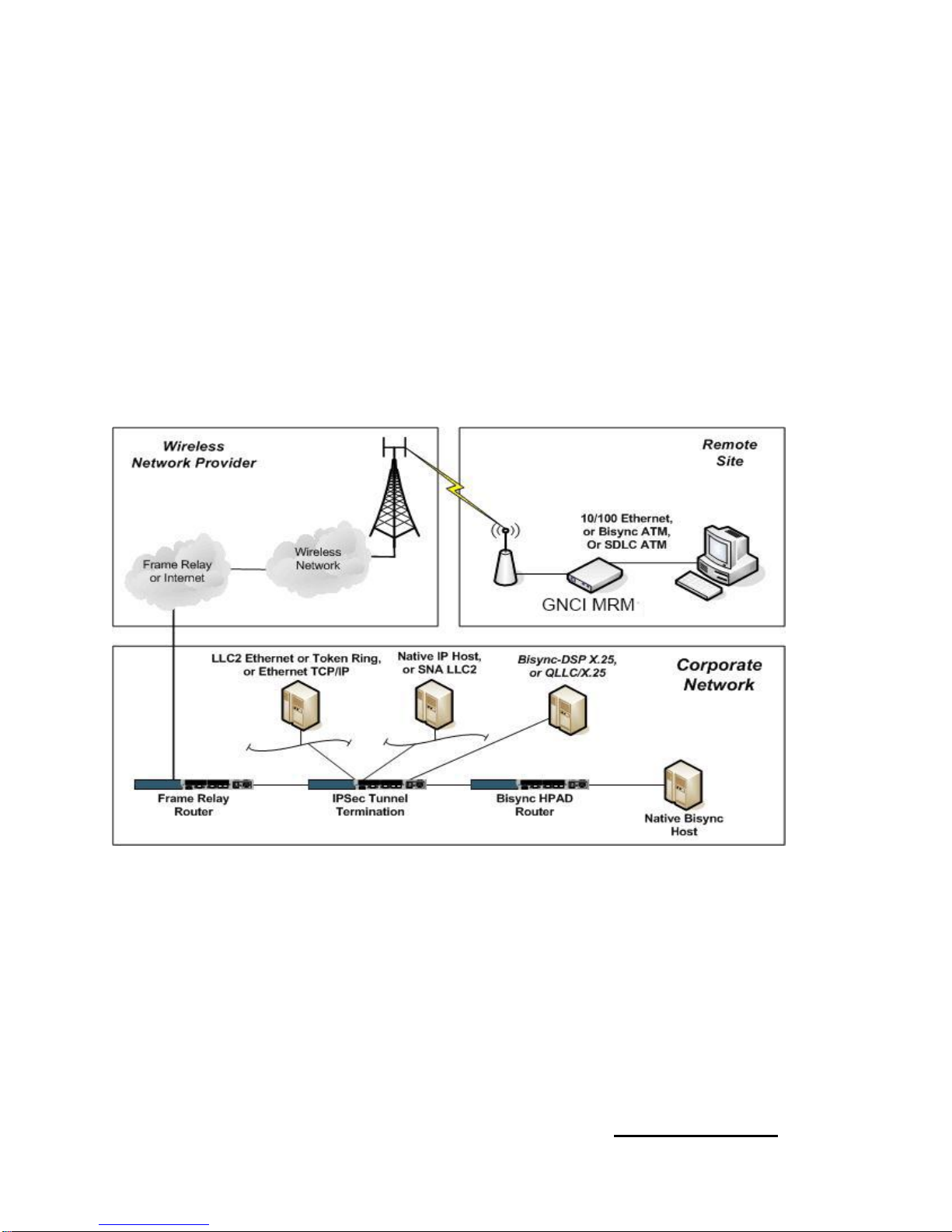
2.2. Network Overview, All Protocols including IP
Figure 2.1
2.3. Network Components
Figure 2.1 shows various components of a wireless network using MRM devices.
Each of these main components is described in this section.
2.3.1. Remote Site Terminal
The remote site terminal is any X.25, SDLC, 3270 BISYNC, or TCP/IP on Ethernet
device. This can be, but is not limited to, ATM or POS machines, and personal
computers.
Note: The firmware on the MRM-X3000 supports IP protocol only.
Page 6

Refer to the MRM-L3000 manual if you are running 3270 BISYNC or
SDLC Protocols
2.3.2. Remote Site GNCI MRM
The remote site MRM operates as a functioning modem on a wireless GSM
GPRS/EDGE/UMTS, HSUPA, HSDPA, HSPA+, LTE network, or a CDMA
1xRTT/EvDO/EvDO RevA, LTE network.
Additionally, the MRM provides for high security using the standards based IPSec
protocol, and encrypts data with the 3DES or AES algorithms. The MRM has a built in
firewall, which provides additional security from unwanted intrusion.
The MRM-X3000 uses a built in 10/100 Ethernet port for TCP/IP communications.
2.3.3. GSM and CDMA Networks
GSM networks are available in the United States, Canada, and many countries
worldwide. GSM is widely deployed and provides for an always on, data connection.
GSM customer networks for secure data transfer are implemented with custom or
private APNs (Access Point Name). APNs are typically deployed to enhance security,
prohibiting communications with any device or network outside of the custom or private
APN. APNs for financial applications typically provide for host location access via
private land line frame relay connections. Higher speed networks using GSM using
UMTS, HSUPA, HSDPA, HSPA+, and LTE technologies are currently being deployed.
CDMA networks are available in the United States; however deployment is limited
outside of North America. CDMA provides bursting rates to 144 kbps on 1xRTT
networks, a maximum 2.4 Mbps on EvDO RevA networks and much higher burst rates
exceeding 8.0 Mbps on newer LTE networks. For secure and financial applications,
CDMA carriers provide for host site access via land line frame relay/MPLS connections.
2.3.4. Host Location Corporate Host
The corporate host shown in figure 2.1 is responsible for providing the transaction
applications driving the ATM or POS system. These hosts can interface to the network
using serial or LAN media, and can connect with TCP/IP, SDLC, X.25, 3270 BISYNC, or
LAN based LLC2.
2.3.5. Host Location Frame Relay Router
The frame relay router shown in figure 2.1 terminates the frame relay connection and
PVC/MPLS interconnecting the host location to the GSM or CDMA network. IP
addressing for this connection is typically provided by the carrier along with private
client designated IP addressing. Shown in figure 2.1 as a device of its own, this may be
a shared device terminating other frame relay connections for other applications, or may
be a device of combined function terminating frame relay, and also providing for IPSec
termination.
Page 7
2.3.6. Host Location IPSec Tunnel Termination
The IPSec tunnel termination device shown in figure 2.1 manages the IPSec tunnels to
each remote MRM unit. It is responsible for maintaining keys for each remote MRM, and
providing 3DES encrypted payload. Additionally, this router must be placed into this
topology at a strategic location, to ensure proper IP routing to hosts and remote MRM
devices. Shown in figure 2.1, this device may be solely used for IPSec termination, or it
may run IPSec in addition to other functions in the network, including the termination of
frame relay/MPLS lines discussed in section 2.3.5. Typically, this device is a Cisco
Systems router or VPN server. Many models of Cisco equipment support IPSec. The
selection criteria used to determine which specific model is best suited for a client
network is dependent upon network size, topology, and other design considerations,
determined prior to any MRM units being deployed in the field.
2.4. Network Addressing
For any network to route data correctly, there must be an addressing and numbering
scheme employed. This section describes the important addressing and numbering
elements for a successful MRM deployment. A network addressing plan is
recommended to be made prior to any major MRM deployment. Specific configuration
tasks related to addressing are discussed in the next chapter.
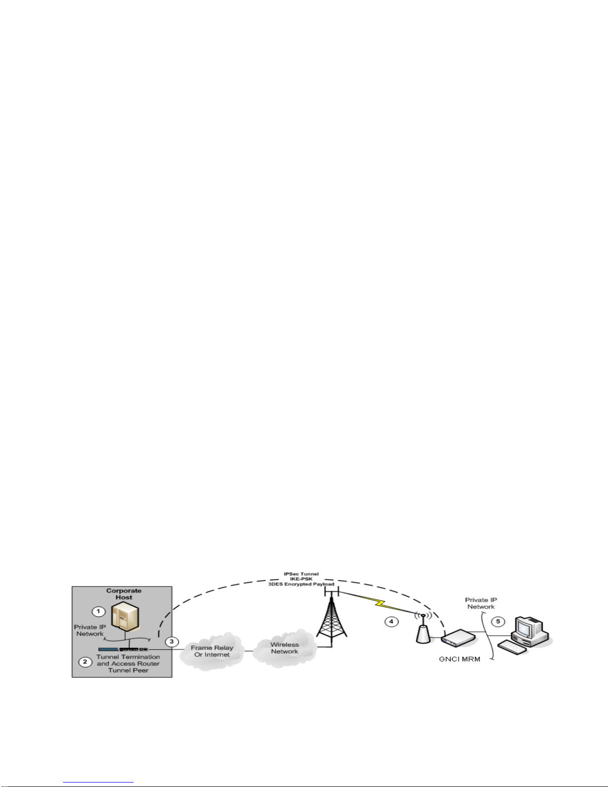
2.4.1. IP Addressing
This section describes the IP addressing requirements across an MRM network.
Below is figure 2.4 indicating important areas of IP address consideration, numbered
one (1) through five (5).
The main concept of IP addressing when using IPSec, is to create a "tunnel" across a
foreign internet or third party network, connecting two private network entities together,
while masking from the end points, the existence of the transit network.
In figure 2.4 below, the private networks 1 and 5 are unaware of the carrier’s Internet
network connecting them together, through the use of the IPSec tunnel across the
network.
Figure 2.4
Page 8

2.4.1.1. Area 1 IP Addressing Host Private Network
The host location private IP network is the private network in which the host is located.
For non-IP host communications, this network is part of the IPSec router terminating the
tunnels. This network typically exists prior to an MRM deployment, and IP network
addressing has been assigned by a network design engineer or administrator, typically
using IP Address for private Internets as described in RFC 1918. The corporate host
and any other service hosts, including management hosts and their respective IP
networks, must be visible to the "remote" device network (Area 5) through the IPSec
tunnel.
2.4.1.2. Area 2 IP Addressing Tunnel Termination
The device(s) in area 2 must be directly connected, or reachable to the IP host in area
1. In addition, the IPSec tunnel terminating device in area 2, must have an IP address
acting as a tunnel peer to the remote MRM devices, and must be reachable through the
CDMA or GSM network. This IP address is normally assigned by the carrier, to ensure
reachability across the carrier’s network to the remote MRM. However, carriers now
offer MPLS Private VPN networks which provide for client-specific IP addressing. If the
carrier assigns the IP addressing, the carrier will typically assign a small IP network
from their IP address space, with a 29- or 30-bit mask. One host from within this
network must act as the IPSec tunnel peer. This network can be assigned on a physical
interface, or a logical (loopback) interface.
2.4.1.3. Area 3 IP Addressing Frame Relay/MPLS Access Point
Frame Relay/MPLS is typically used to connect the host network to the carrier. A
customer can use an existing frame relay/MPLS circuit. Prior to the introduction of
MPLS circuits, a PVC connection to the carrier was required, or in some cases, a
completely new frame relay line was used, with a PVC connection to the carrier. This
determination is made during the design stage of a network. The carrier will assign an
IP subnet for use on the frame relay PVC, typically with a 30-bit mask, providing for one
IP at the client router for the PVC, and one IP at the carrier’s router for the same PVC.
For routing purposes, the IP address assigned to the carriers router, becomes the
gateway address to reach Area 4 IP networks (MRM radio IP addresses). This address
is used for static routing purposes in the client frame relay router, as the next hop
address to reach the distant MRM IP range (Area 4). Routing protocols are not
permitted on the frame relay link between the client and carrier. Frame relay DLCI
numbers are assigned by the frame relay carrier responsible for the PVC link between
the client and the carrier, and are made available when the PVC order is complete.
Note: Recently Carriers have migrated away from Frame Relay and are now only
offering Private VPN Tunnels over MPLS Circuits.
2.4.1.4. Area 4 IP Addressing MRM Radio IP
In both GSM and CDMA networks, the IP address assigned to the radio device
connecting to the carrier network is made dynamically. The IP addresses are
determined by the carrier, and assigned to the modem dynamically during connection
time. In both CDMA and GSM networks, the modems connect to the network using the
PPP protocol, and are assigned IP addresses during this connection setup. IP
Page 9

addresses that are dynamically assigned are typically known to be within an IP subnet
range, which is useful to know for the purposes of IPSec configurations at the host
network. In the case of a private or custom APN on the GSM network, the IP address
range which can be assigned to the connecting modems is tightly defined, and is a
range of IP addresses which will only be assigned to modems belonging to the private
APN, and thereby will only be assigned to modems belonging to a particular client.
Some GSM carriers offer to use IP address space for the modems, which can be
specified by the client.
From the perspective of the MRM device, the IP address assigned to the radio of the
MRM at connection time, acts as the devices Wide Area Network (WAN) interface. This
IP address acts as the IPSec tunnel peer, communicating with the host network tunnel
peer. Since the IP Address is dynamic, only the peer at the host IPSec tunnel
termination router is known. Therefore, specific IPSec configuration is required at the
host, examples of which are discussed in the next section.
2.4.1.5. Area 5 IP Addressing Remote Private IP Network
The remote location private IP network is a private IP network in which the remote
device (ATM or POS) is connected to or associated. This network is assigned prior to
an MRM deployment, and IP network addressing has been assigned by a network
design engineer or an administrator. This is typically done using an IP address for a
private network as described in RFC 1918 and form part of the IP address plan for the
wireless network.
This network communicates with the Area 1 private network (Host Network), over the
IPSec tunnel. For Ethernet connected TCP/IP devices, an IP network must be
assigned, and, individual host IP addresses from this network must be assigned for the
MRM's Ethernet port, and the ATM/POS device.
Example: IP Network: 192.168.10.0/30
MRM Ethernet Port: 192.168.10.1
ATM/POS device: 192.168.10.2
This IP network operates on a virtual (loopback) port within the MRM, not associated to
any physical interface, for the purposes of IPSec private networking with the host
private network.
2.4.2. Other Network Numbering Requirements
For legacy protocol implementations, other network numbering assignments are
required, such as X.121 addresses and poll codes. Refer to the MRM-L3000 Installation
Guide for legacy protocols.
Page 10

MRM Serial Number
1010150438
Radio Card Serial Number
356471031535837
SIM Card Number
89302370105215208037
Mobile Telephone Number
949.555.1212
APN Name
mybanksapn.com
Username
GSM
Password
network
3. MRM-X3000 Configuration
This chapter provides instruction for the configuration of the MRM for remote site
operation.
In order to use the MRM, a wireless service account must be established with a wireless
carrier, and the MRM configured with account specific information.
3.1. Preparation
This section describes what information is required before configuring the MRM for the
wireless services provider.
3.1.1 GSM Preparation
The GSM service provider will provide the following for account activation.
. GSM SIM Card (with SIM card number and mobile telephone number)
. APN Name
. Username
. Password
The GSM SIM card has a SIM card number and an associated mobile telephone
number. Records of these numbers should be carefully kept, as they can be required
later for troubleshooting with the carrier. It is recommended that records be kept for
each MRM location that includes the MRM serial number, the radio card serial number,
the SIM number, and telephone number.
In most cases, the APN name will remain the same for all remote MRMs belonging to
the same client.
Username and password may be supplied by the carrier as further authentication to
connect to the network. Note that some carriers do not implement the
Username/password as a requirement.
Table 3.1 Example GSM Remote Site Account Information
Page 11

MRM Serial Number
1010150438
Radio Card Serial Number
09112561854
Activation Code
884325
System ID
16422
Mobile Telephone Number
949.555.1212
Username
9495551212@mycarrier.com
Password
mycarrier
3.1.2. CDMA Preparation
The CDMA service provider will provide the following for account activation:
. Username
. Password
. Telephone Number
. Activation Code
. System ID (SID)
Radio cards should be activated in a laptop using the carrier’s network activation
software. Once completed, the card can be inserted into the MRM.
The activation code and System ID are required only at initial activation time, using the
carrier’s activation software. The Username and password are required for
configuration in the MRM, if required by the carrier. Records should be kept for each
remote MRM with the noted information from the example below.
Table 3.1.2 Example CDMA Remote Site Account Information
3.2. Components Required For Configuration
This section describes the required equipment, cables, and software for the
configuration of the MRM.
3.2.1. Required Components for GSM Configuration
Configuration of the MRM requires the user to provide the following:
* A desktop or laptop computer, with an Ethernet communications port and an
Express Card/USB ports
* An Ethernet cable (either straight-through or crossover)
* A browser such as Internet Explorer or Mozilla Firefox
3.2.2. Required Components for CDMA Configuration
Configuration of the MRM requires the user to provide the following:
* A desktop or laptop computer, with an Ethernet communications port and an
ExpressCard / USB port
* An Ethernet cable
* A browser such as Internet Explorer or Mozilla Firefox
Page 12
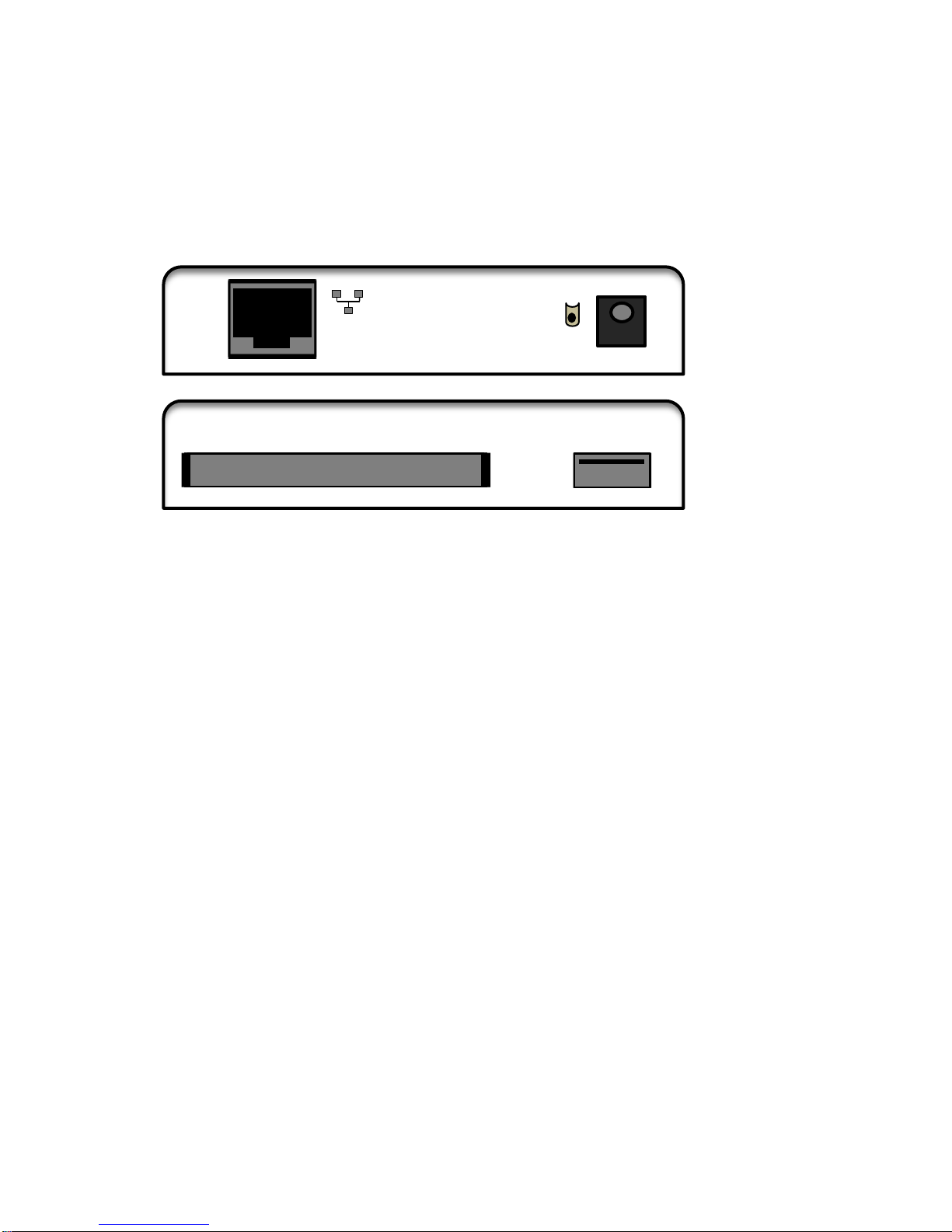
D -IN I
DC-IN
Init.
D -IN I
3.3. Accessing the MRM for Initial Configuration
The MRM unit is shipped with a default configuration, which includes a pre-defined
Ethernet port, Ethernet (facing the rear of MRM, it is the leftmost Ethernet port).
Figure 3.3.1 MRM Side Panels
Ethernet Port
Ethernet port is factory set for IP address 192.168.10.1 with a mask of
255.255.255.252. To access the MRM configuration, a connection must be made from
the computer's Ethernet port to the MRM's Ethernet port, via an Ethernet crossover
cable. The IP address settings in the computer must be set to specify IP address
192.168.10.2 with a mask of 255.255.255.252, and a gateway of 192.168.10.1.
Follow these steps to access the MRM configuration:
Step 1 . Power on the MRM unit with radio card inserted into either the
ExpressCard slot or the USB port. The port selection will depend on which
type of wireless aircard you are using. Connect the power supply cable to
AC Power, and to the 6 VDC receptacle on the MRM.
Step 2 . Connect your computer to the MRM Ethernet port (shown in Figure 3.3.1)
using a standard Ethernet cable.
Step 3 . Set the IP address, subnet mask, and gateway in your computer, as
shown on the next page.
Step 4 . Using a web browser, connect to the default IP address of 192.168.10.1.
Page 13
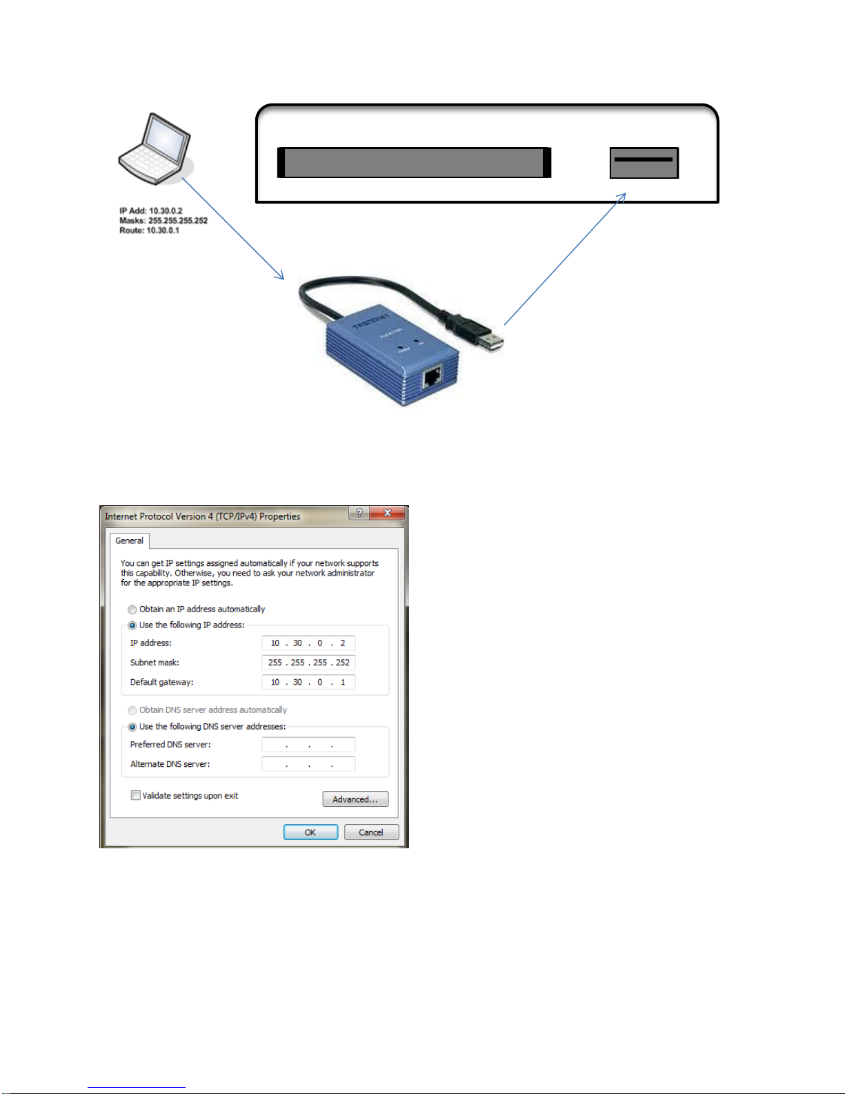
D
-
Figure 3.3.2 Accessing the MRM via a Static IP address using USB port
Ethernet IP Add: 10.30.0.1
Ethernet Cable Masks: 255.255.255.252
Follow these steps to access the MRM configuration:
Step 1 . Power on the MRM unit without the radio card inserted in the USB port, by
connecting the power supply cable to AC power outlet, and to the 6 VDC
receptacle on the MRM. Note: A Trendnet TU2ET100 USB-to-Ethernet
adapter is required to connect through the MRM-X3000 USB port.
Page 14
Step 2 . Connect your computer to the Ethernet port of the Trendnet TU2ET100
adapter. Then connect the USB adapter to the USB port on the MRMX3000. (Shown in Figure 3.3.2.)
Step 3 . Configure your computer to receive an IP address:
10.30.0.2/30 (subnet mask of 255.255.255.252).
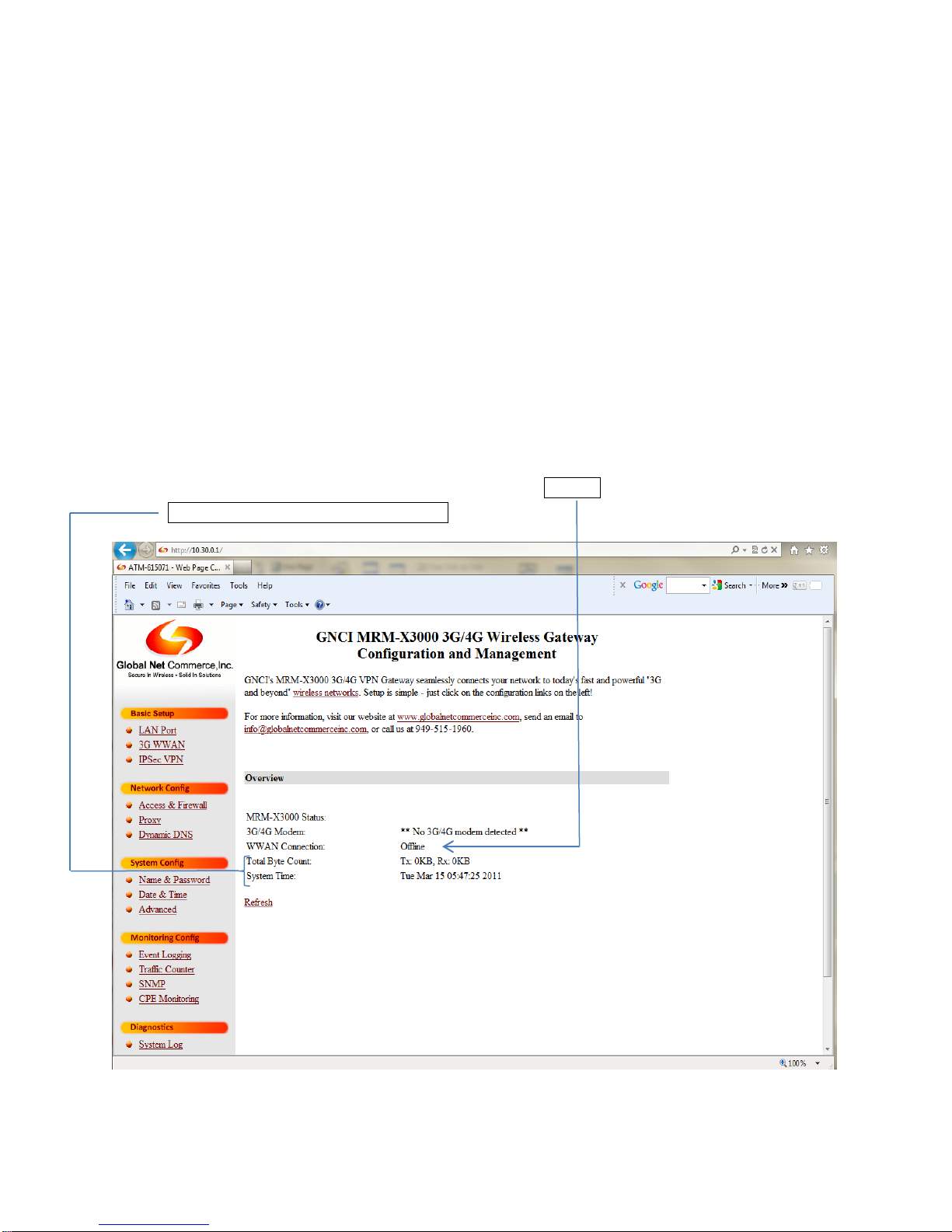
Step 4 . Using a web browser, connect to the default gateway IP address of
10.30.0.1
MRM-X3000 Home Screen
Home Screen Start Section 3.4.1
1. A summary of the MRM-X3000 operation and connectivity status can be obtained by
Clicking on the GNCI logo in the upper left hand portion of the Home Screen
2. The information on the Home Page will provide WWAN/carrier connection status,
Total Bytes count and System Time.
Page 15
3.4. Configuring the MRM System Parameters
This section describes the configuration of MRM system parameters.
3.4.1. Default Username and Password
The default system username is “admin”, and the default system password is “gnci”.
You can change the password in the Name and Password section, under the SYSTEM
CONFIG heading.
3.4.2 Basic Setup
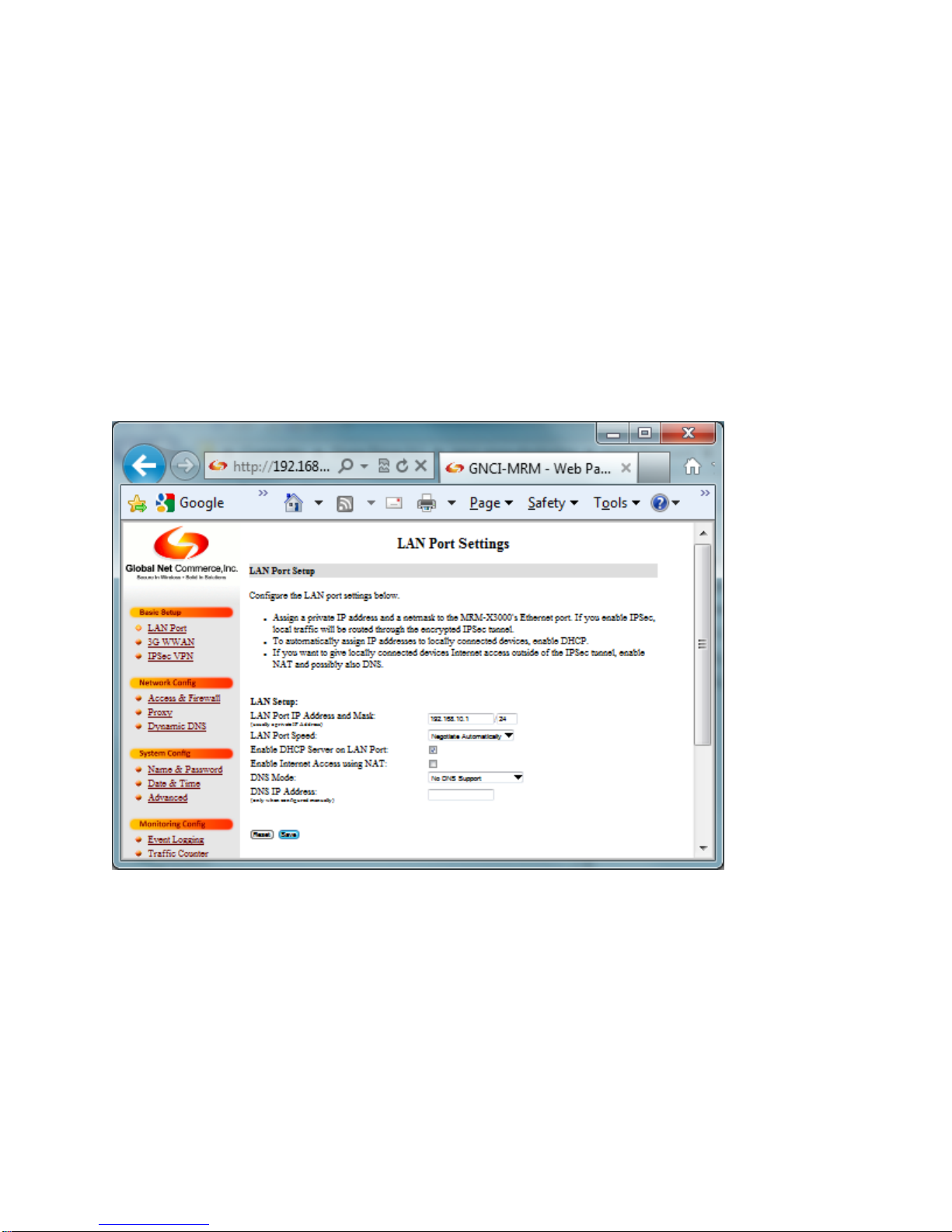
3.4.2.1 LAN Port
LAN Port Setup
LAN Port IP Address and Mask: Enter the IP address you wish to use for the MRM.
LAN Port Speed: Speed settings for the Ethernet port on the MRM. Settings are
Negotiate Automatically, 10 Mbps Half Duplex, 10 Mbps Full Duplex, 100 Mbps Half
Duplex, 100 Mbps Full Duplex.
Enable DHCP Server on LAN Port: Check this box if you would like the MRM to act as
a DHCP server.
Page 16

Enable Internet Access using NAT: Check this box if you would like devices connected
GSM Account Information
Value
Description
GSM APN
blank
Enter the APN name for the customer network.
Mandatory field if this MRM is used in GSM mode.
Username
Blank
Enter the GSM Username. (Optional)
Password
Blank
Enter the GSM Password. (Optional)
CDMA Account Information
Value
Description
Username
Blank
Enter the CDMA Username. (Optional)
Password
Blank
Enter the CDMA Password. (Optional)
to the MRM to be able to access the Internet using Network Address Translation.
DNS Mode: Choose the DNS mode you wish to use. Other options are available from
the drop-down menu.
DNS IP Address: Enter the IP address of your DNS server, when configured manually.
3.4.2.2 3G/4G WWAN Wireless WAN Setup
Table 3.4.2.1
Page 17

IPSec VPN Parameter
Default
Description
IPSec VPN Host IP
Blank
The Tunnel Peer IP Address found on the IPSec
Router at the Host location.
Destination Private Network
Blank
The private network address from which the host
location this MRM will communicate.
Local Private Network
Blank
The private network assigned to this MRM for IPSec
communications.
Phase 1 Encryption / Hash /
DH Group
Blank
Contact GNCI Technical Support where advanced
settings are required
IPSec Pre-Shared Key
Blank
Enter the Pre-Shared Key (PSK) for this IPSec
connection
Press Reset/Save button to proceed to the next step. Selecting Reset resets the values
in your computers browser, not the configuration values in the MRM.
3.4.2.3 IPsec VPN Settings
Select the Enable IPSec VPN Tunneling check box to enable IPSec on this MRM. By
default, the MRM runs IPSec with 3DES encryption, uses IKE, and PSK.
Table 3.4.2.3
Page 18

Confirm PSK Here
Blank
Re-enter the PSK to validate. If the two keys entered
do not match, the MRM will indicate an error.
Encryption Key Timeout
1
Lifetime of encryption key and ISAKMP SA
Dead Peer Detection
Default
Description
Use Dead Peer Detection
Checked
Check or uncheck box to enable /disable DPD.
DPD Timer
90
Choose a value of 15 to 300 minutes, in increments
of 5 min.
DPD Max Retries
3
Max number of DPD retries before the MRM
declares the IPSec tunnel dead. Range is 2 to 20 in
increments of 1.
Action on DPD Event
Restart
Wireless
and IPSec
Select what action to take in the event of a Dead
Peer Detection. The options are Restart Wireless
and IPSec or Restart IPSec.
Press the “Save” button to proceed to the next step. Selecting Reset resets the values
in your computer’s browser, not the configuration values in the MRM. Select Reset to go
back to the default settings, this will allow you to re-enter changes. Once all changes
are completed, select “Save.” If all configuration entries have been made, you can save
the final configuration by selecting the “Apply New Config” Button.
4. MRM Installation
This chapter covers the physical installation of the MRM.
4.1. Preparation
The MRM unit must be configured prior to final installation. See section 3 for
configuration instructions and examples.
Note: A complete site survey and site analysis is recommended prior to installing
the MRM. The site survey and site analysis is designed to qualify the remote site
for consistent/reliable radio signal stability. Test results and radio signal stability
should be documented for each remote site.
! Note !
Special Note For CDMA Installations
CDMA radio cards must be activated in a laptop or desktop computer prior to installation
in the MRM. Carefully follow the instructions provided to you on the Wireless AirCard
Installation CD, or by the automated instructions imbedded in the CDMA wireless
modem.
Ensure the card is functioning correctly and can connect to the wireless carrier prior to
inserting the card into the MRM.
Page 19

4.1.1. Required Equipment
Item Description
Installation Requirement
Multi-Radio-Modem Base Unit
Required for all installations
MRM Power Supply
Required for all installations
CDMA Radio USB/ExpressCard
Required for CDMA installations
GSM Radio USB/ ExpressCard
Required for GSM installations
SIM Card
Required for GSM installations
GSM Antenna
Required for GSM installations
CDMA Antenna
Required for CDMA installations
ULSSC Cable (MRM-L3000 only)
Required for Bisync or SDLC installations
(MRM-L3000 only)
Ethernet Cable
Required for TCP/IP installations
ATM / POS / or connecting device
Required for all installations
AC 120 V Power Outlet
Required for all installations
Small Slotted Screw Driver (MRML3000 only)
Required for Bisync or SDLC installations
(MRM-L3000)
The table below indicates the equipment required for the type of installation.
Table 4.1.1
Optional mounting hardware may be required at some remote sites to physically secure
the devices, depending on installation requirements.
4.2. Antenna Considerations
A base small antenna is provided with the MRM shipment. GSM and CDMA antennas
have different connectors.
!! Warning : FCC RF Exposure Guidelines
While this device is in operation, a separation distance of at least 20 cm must be maintained between the
radiating antenna and the body of all persons exposed by the transmitter to meet FCC exposure
guidelines.
To comply with FCC regulations limiting both maximum RF output power and human exposure to RF
radiation, the maximum antenna gain must not exceed 6 dBi in the cellular band and 4 dBi in the PCS
band.
4.2.1. Antenna Location
Locate the antenna as far away from personnel as possible to minimize signal blocking.
For optimum reception, position the antenna above the height of personnel and nearby
equipment or structures. Locate the antenna to allow as free a radiation pattern as
possible.
4.2.2. Antenna Ground Plane
Page 20

If possible, ensure the antenna is mounted on a good ground plane (ferrous metal
surface).
4.2.3. Proximity to other antennas
In general, avoid locating the antenna closer than 1.5 meters (5 feet) to another
antenna.
4.3. Installation Procedure
To install the MRM at a remote location, use the following steps:
1) Insert the provided GSM or CDMA radio card into the ExpressCard or USB port
on the side panel of the MRM.
2) Install the MRM at a suitable location, within cabling distance of the connecting
device (either RS-232 or Ethernet cable) and the antenna location.
3) Install the antenna at a suitable location, and connect into the radio card.
4) Connect the RS-232 or Ethernet cabling to the connecting device. (For MRM
L3000 only: If connecting the RS-232 cable (ULSSC Cable), ensure that the DB25 end of the cable is securely attached to the connecting device using a screw
driver.)
5) Connect the power supply to the MRM.
6) Connect the power supply to a 120 VAC electrical outlet.
Note: An uninterruptible power supply (UPS) or surge protector is recommended
for all installations.
The MRM installation is now complete and ready for testing or use.
5. MRM Status and Monitoring
This section describes how to monitor the MRM, check for status, using the web
interface.
5.1. Using the Web Interface for Monitoring and Status
The web interface is used to display information about the current operational state of
the MRM, as well as perform some basic diagnostics.
5.1.1. Accessing the Overview Screen
The web interface main screen provides a simple overview of the current RF status, as
well as the current status of legacy or Ethernet connections.
Page 21

To access the overview, use a web browser, and point to the appropriate IP address
using HTTP. To review or see an updated overview, or to go back to the overview from
a different page, click on the Global Net Commerce Inc. logo at the top left of the
screen. See below example, which shows a configured MRM overview on a CDMA
network.
Page 22

6.1.1 Network Config
Firewall Parameter
Default
Description
Allow Access From
blank
Enter either individual IP hosts, or specify IP networks
which will be permitted to access the MRM.
Allow Access From
blank
same as above
Allow Access From
blank
same as above
6.1.1.1 Access & Firewall
Check the Enable Firewall check box to enable the IP firewall on the MRM. The MRM
will deny all traffic from all IP addresses except the IPSec tunnel peer, unless specified.
Table 6.1.1.1
Page 23

6.1.2 3G WANN Setup:
Selecting Reset resets the values in your computers browser, not the configuration
values in the MRM.
Select Reset/Save to complete the configuration.
Page 24

6.2.1 Dynamic DNS
Dynamic DNS Setup:
Use Dynamic DNS Provider: Select your Dynamic DNS provider from the adjacent
list. Select from the drop-down menu for available options.
DDNS Domain Name: Enter the domain name used by your Dynamic DNS provider.
DDNS Username: Enter the appropriate DDNS Username.
DDNS Password: Enter the appropriate DDNS password.
Page 25

7.1.1 System Config
7.1.1.1 Name & Password
MRM-X3000 Host Name
7.1.1.1 Configuring Host Name
Each MRM unit has a configurable hostname, which can be up to 20 characters in
length. The host name can be assigned completely at the discretion of the client.
Hostnames appear in syslog and SNMP messages for monitoring purposes. Hostnames
can assume the name of connecting devices such as ATM or POS controllers. For
example, the MRM hostname could be MyBankATM54321.
Page 26

MRM-X3000 Authentication for RADIUS
Password Configuration
The Password configuration is accessed by clicking on Password located under the
SYSTEM section.
Click on the Name and Password Tab under the SYSTEM category on the left side of
the browser screen to access this configuration.
Enter the new password for the MRM in the box provided, and confirm the password as
indicated. Press the Apply button to make the change.
Note: The actual passwords are not displayed on the screen for security purposes.
7.1.1.2 Date & Time
Page 27

7.1.1.2 Configuring the Date and Time Settings
The Date and Time configuration is accessed by clicking on Date and Time located
under the SYSTEM section.
There are three ways to set the date and time on the MRM unit.
1) Set the date and time to the same date and time as the current date and
time on the computer configuring the MRM.
Press the appropriate Set Date and Time button.
2) Manually set the date and time. Use the pull down boxes to manually set
the date and time to specific value.
Press the appropriate Set Date and Time button.
3) Set date and time using a remote NTP server.
The MRM will use the Network Time Protocol to synchronize its clock
with a remote NTP server.
Enter the Remote NTP Server IP address in the box provided. This IP
address needs to be reachable from the wireless network or via the IPSec
tunnel. If domain names are supported, you substitute a domain or
machine name in place of an IP address (for example “pool.ntp.org”).
The date and time will typically be in UTC (Universal Time Coordinated),
and therefore, a time zone adjustment may be required, such as -5 for
EST and -8 for PST. Enter the Timezone Adjustment value from the drop
down box indicated.
The MRM will automatically adjust itself for daylight savings time if the
Adjust for Daylight Saving Time checkbox is checked.
Press the Save button for the NTP setting to take effect.
Page 28

7.1.1.3 Advanced
Click on the “Advanced” button under the system heading. Click on Flash Upgrade to
upload new firmware to your MRM. Follow the prompts.
Note: Your firmware version must be stored on your computer, with accessible file
permissions.
Page 29

7.1.1.4 Flash Upgrade Screen
1. Click on the “Advanced” button under the system heading. Click on Automatic
Background Pinging to generate background traffic on the data link.
2. Click on the “Advanced” button under the system heading. Click on Failsafe
Configuration to designate a currently active configuration as a backup
configuration in case of a misconfigured unit, you can revert back to your base
configuration by pressing the INIT button located next to the power source on the
MRM for 10 to 15 seconds.
3. Click on the “Advanced” button under the system heading. Click on Configuration
Files to save and load configuration files between your computer and the MRM.
4. Click on the “Advanced” button under the system heading. CDMA/EvDO Modem
activation/PRL upgrade. Currently, activation can be done for Sierra Wireless
and Novatel Wireless modems only. Follow the instructions to perform the
upgrade.
5. Click on the “Advanced” button under the System Configuration heading. Press
Reboot to perform a software restart on the MRM.
Page 30

Component
Description
MRM Unit
The running MRM unit to be upgraded
Ethernet cable
Ethernet cable to connect the MRM to the
computer
Computer (Laptop or Desktop)
Computer used to initiate the upgrade
MRM firmware file
New MRM firmware file to send to the MRM.
7.2.1 Installing New Firmware on the MRM
This chapter discusses how to upgrade the firmware of the MRM.
7.2.1. Preparation
In order to upgrade the MRM firmware, it is assumed that the MRM unit is already
configured for IP, Bisync, or SDLC operations, and is reachable via the IP protocol,
either by a locally attached Ethernet cable, or over the wireless network.
7.2.2. Required Components
The components required for a firmware upgrade depend on if the upgrade is to be
performed locally via Ethernet cable, or remotely over the wireless network.
7.2.3. Local Ethernet Upgrade using HTTP
Use of the HTTP Flash Upgrade method is more straight-forward and highly
recommended. Use of Microsoft Internet Explorer 5.0 or later, or Mozilla Firefox 6.0 or
later, is required, for support of browser file uploads.
Table 7.2.3 shows the components required to upgrade the MRM firmware, when
performing the upgrade via a locally attached Ethernet cable.
Page 31

Using your computer’s web browser, select the “Advanced” option from the “System Config” on
menu at the left-hand side. The MRM-X3000 will present the “Flash Upgrade” screen (shown
above in Figure 7.2.3). Enter the filename of the MRM flash file in the text field to the right of
“Filename” below the “HTTP Flash Upgrade” heading, or (recommended for ease) click the
“Browse” button and use your Windows File Explorer to select the MRM flash file.
Select “Ignore Firmware Version Information” checkbox if you are downgrading.
Typically, you should NOT select “Revert to Factory Configuration” since you likely wish to
maintain your existing configuration.
Then select “Start HTTP Upgrade”, and wait for the firmware upgrade to complete without
disruptions.
Note: Once the MRM firmware has been updated, go to “System Status” to verify that the
firmware has changed.
See next page for System Status screen.
Page 32

Component
Description
MRM Unit
The running MRM unit to be upgraded
Ethernet cable
Ethernet cable to connect the MRM to the
computer
Computer (Laptop or Desktop)
Computer used to initiate the upgrade
TFTP or FTP Server
Program used to send the new flash file to the
MRM.
MRM firmware file
New MRM firmware file to send to the MRM.
!! Warning: Do NOT power off or otherwise interrupt the MRM during this
process, as this will cause permanent damage to the unit which is not covered under
warranty.
7.2.4. Local Ethernet Upgrade using TFTP or FTP
Table 7.2.4 shows the components required to upgrade the MRM firmware, when
performing the upgrade via a locally attached Ethernet cable.
Page 33

D
-
Figure 7.2.4 shows the topology required for a successful local upgrade. Use of these
instructions require a Trendnet TU2ET100 USB-to-Ethernet adapter connected between
the computer to the MRM-X3000 USB port. Alternatively, computer connection with
MRM-X3000 Ethernet port requires alternative IP configuration which is dependent on
your carrier’s static IP or dynamic IP, which is more complicated (contact GNCI for
technical assistance).
Note: Once the MRM firmware has been updated, go to
“System Status” to verify that the firmware has changed.
See next page for System Status screen.
Page 34

Current MRM Ethernet IP Address
10.30.0.1
Current MRM Ethernet IP mask
255.255.255.252
Computer IP address
10.30.0.2
Computer IP mask
255.255.255.252
Computer Gateway Setting
10.30.0.1
7.3.1. Local Upgrade IP addressing
Select an appropriate IP address, mask, and gateway for the computer connecting to
the MRM, depending on the current IP settings on the MRM Ethernet port. Example:
Ensure that a ping from the computer to the MRM is successful prior to continuing to the
next step.
Note: Some computers have built-in firewalls, which may need to be turned off or
adjusted to permit FTP or TFTP traffic.
Page 35

7.3.2 Local Upgrade Procedure
Component
Description
MRM Unit
A running MRM unit on the wireless network to
be upgraded
Computer (Laptop or Desktop)
Computer used to initiate the upgrade
TFTP or FTP Server
Program used to send the new flash file to the
MRM
MRM Flash file
New MRM flash file to send to the MRM.
1) Start TFTP or FTP server on the computer, with the new MRM flash file stored in
an appropriate directory.
2) Telnet to the MRM device, and log on to the MRM with the current username and
password.
3) From the # prompt, issue the following command:
For TFTP : netflash x.x.x.x filename
Where x.x.x.x is the IP address of the TFTP computer and filename is the
filename of the new MRM flash file. Filenames are case sensitive.
For FTP: netflash -f x.x.x.x filename
…where the -f operand specifies use of FTP, x.x.x.x is the IP address of the
TFTP or FTP server and filename is the filename of the new MRM flash file.
Filenames are case sensitive.
The netflash routine saves the current MRM configuration, loads the new flash
file, and then reboots.
!! Warning: Do NOT power off or otherwise interrupt the MRM during this
process, as this will cause permanent damage to the unit which is not covered under
warranty.
7.3.3. Remote Firmware Upgrade
Table 7.3.3 shows the components required to upgrade the MRM firmware, when
performing the upgrade over the wireless network.
Note: The MRM unit must be able to reach the computer over the network for the
upgrade to be successful. Ensure that you are able to ping the MRM before initiating the
upgrade.
Figure 7.3.3.0 shows a sample topology for a successful firmware upgrade over the
wireless network.
Figure 7.3.3.0
Page 36

7.4.1. Remote Upgrade IP addressing
Upgrading the firmware remotely assumes that both the MRM and the TFTP or FTP
server are already configured with fixed IP addresses.
Note: Some computers have built-in firewalls, which may need to be turned off or
adjusted to permit FTP or TFTP traffic.
7.1.1.1. Remote Upgrade Procedure
1) Start TFTP or FTP server on the computer, with the new MRM flash file stored in
an appropriate directory.
Important Note ! The performance of the remote firmware upgrade over
the wireless network is much faster when using FTP, compared to the
dramatically slower TFTP.
2) Telnet to the MRM device, and log on to the MRM with the current username and
password.
3) From the # prompt, issue the following command :
For TFTP : netflash -I x.x.x.x y.y.y.y filename
Where y.y.y.y is the IP address of the TFTP computer, x.x.x.x is the source IP
address of the MRM (usually the IPSec Local Private Address), and filename is
the filename of the new MRM flash file. Filenames are case sensitive.
For FTP : netflash -f -I x.x.x.x y.y.y.y filename
Where the -f operand specifies to use FTP, y.y.y.y is the IP address of the TFTP
computer, x.x.x.x is the source IP address of the MRM (usually the IPSec Local
Private Address), and filename is the filename of the new MRM flash file.
Filenames are case sensitive.
The netflash routine saves the current MRM configuration, loads the new flash
file, and then reboots.
Page 37

Monitoring Config
Event Logging
System Log Setup
System Log – Level of Detail: Select the level of detail which will be posted to the MRM’s system log.
Increased detail decreases the duration of the log file. The converse is also true. Options are:
Show Last Entry on Top: Check this box if you would like system log posts to be displayed in reverse
chronological order (newest to oldest entries) from the top.
Enable 3G Wireless Stats Logging:
Radio Statistics Log Interval: Choose the interval between Radio Statistics (RSSI, channel, etc.) posts.
Note: See screen options on next page.
Page 38

Other Options:
Log to Remote Server
Enable Remote Logging: Check this box to enable logging to a remote server. This is usually not
recommended.
Page 39

Remote Server – Level of Detail: Select the level of detail which will be posted to the remote system log.
Increased detail decreases the duration of the log file. The converse is also true.
Note: click on down arrows for alternative logging settings
Remote Server IP Address: Enter the IP address of the remote logging server.
Page 40

Traffic Counter
WWAN Interface Byte Counter
[Clear Counter now] Button: Click this button to set the MRM’s Total byte counter to Zero (0).
Enable Monthly Counter Reset: Check this box if you would like the byte counter to reset monthly on a
given day (detailed in the next field).
Counter Reset Date: Day of the month on which the byte counter will reset (at 0000). For instance,
select 1 if you would like the counter to reset at 0000 on the 1st of each month. This is usually employed
to reset on the account statement date.
SNMP Configuration
Page 41

8.1.1.3 SNMP
8.1.1.3. Configuring SNMP Move to SNMP screen
8.1.1.4 SNMP Trap Configuration
This section discusses the MRM’s configuration and implementation of SNMP Traps.
8.1.1.5. MRM Implementation of SNMP Setup
The MRM uses SNMP Traps for reporting status and alarms.
SNMP generic traps are used to report all Up/Down events for Bisync, SDLC, DSP,
QLLC, Ethernet TCP/IP, and Radio Reception (RSSI) information. Generic traps are
augmented with text strings for more specific information on the Up/Down event, and is
always preceded by the MRM Nodename. Two specific generic traps are used, shown
below in table X.X.X.2
Table X.X.X.2 SNMP Generic Traps
Page 42

SNMP OID
Trap Name
Version Supported
.1.3.6.1.6.3.1.1.5.3
Link Down
V1 & V2
.1.3.6.1.6.3.1.1.5.4
Link Up
V1 & V2
Special Note for Trap 11:
Trap 11 is a trap sent on a configurable time interval for reporting general status of the
MRM. The additional text of trap 11 will vary depending on the current RSSI value, the
current serial protocol status, or the current Ethernet IP status.
8.1.1.6 Configuring SNMP Set up and SNMP Trap Set up under the
Monitoring Config Tab in the browser
Check the Enable SNMP and Traps by checking the SNMP Setup box. Leave
unchecked if SNMP will not be used.
Proceed to SNMP Read Community String (Labeled Public)
Proceed to SNMP Write Community String (Labeled Private)
Proceed to Listen on Interface(s)
Proceed to Only Reply to IP Address or Network
Press Next button to proceed to Step 2. Selecting Reset resets the values in your
computers browser, not the configuration values in the MRM.
8.1.1.7 SNMP Trap Setup
Set the SNMP traps to your Host SNMP server IP address
Background logging messages are Syslog messages which will write to the system log
at pre-configured intervals, the current receive level of the modem (RSSI), and current
status of legacy protocols. To enable background logging, check the box labeled Enable
SNMP as shown above, and indicate the time/ frequency of this logging in minutes, by
selecting the appropriate interval in the drop down box.
These messages will be written to the local syslog (default), and can also be sent to a
remote syslog server.
Additionally, the MRM can be configured to send alerts due to significant changes in the
receive signal level (RSSI), to the local or remote syslog.
To enable this feature, check the appropriate Alert Logging boxes under the SNMP Trap
Setup section of the Monitoring Config screen.
Table 8.1.1.7
Page 43

SNMP Parameter
Default
Description
SNMP Server IP address
blank
Enter the IP Address of the SNMP server.
Dest. is across IPSec
Tunnel
unchecked
If using IPSec, and the SNMP server is part of the host
location private IP network, this box must be checked to
ensure a correct source IP address for the SNMP packet.
SNMP Version
V2
Select V1 or V2 from drop down box.
Serial Port L1 Trap
unchecked
Check the checkbox to enable Serial port Up/Down traps
Bisync/SDLC L2 Trap
unchecked
Check the checkbox to enable Serial L2 Up/Down traps
X25.DSP/QLLC L3 Trap
unchecked
Check the checkbox to enable DSP/QLLC Up/Down traps
Ethernet Device
Up/Down
unchecked
Check the checkbox to enable Ethernet Up/Down traps.
You will also need to enter an IP address of the Locally
Attached Device.
Ethernet Link State
checked
Check to enable Ethernet port traps
Warn on low RSSI
unchecked
Check the checkbox to send RSSI warning as defined in
hostname/logging configuration.
Send Periodic Status
Updates
checked
Check to send periodic trap 11 status messages at the
configured interval.
Include RF Byte Count
checked
Include the RF TX/RX byte count in the trap 11 message.
Status Update Interval
15
Select interval to send trap 11 status messages in
increments selected in drop down box.
IP address of Locally
Attached IP Device
blank
Enter the IP address of the Ethernet connected device for
Ethernet Up/Down messages
Selecting Reset resets the values in your computers browser, not the configuration
values in the MRM. Select Apply to save this configuration.
The below example shows a screen shot of inbound MRM SNMP traps being received
at an SNMP station. All eleven MRM traps are shown.
Page 44

CPE Monitoring
You can configure the MRM-X3000 to monitor an attached IP device.
Check “Enable” and enter the IP address of the device to be monitored.
Note: In ATM deployments this IP address will always be the IP address of the ATM.
Page 45

9.1.1 Diagnostics
9.1.1.1 System Log
9.1.12. Accessing the System Log
Click on the System Log button Under the Diagnostics Tab to display the contents of the
system log.
There are two System Log options available through the web interface:
1. System Log History
2. Live System Log Events (Note: This requires Adobe Flash and will create
additional traffic while active. It does not work with HTTPS over WWAN)
Press Clear to clear the system log, and Refresh to display the most recent syslog
activity.
Page 46

Port Status:
9.1.3
Accessing the Ports and Connections Screen
Click on the Ports and connections button to display the current status of all physical
and logical ports in the MRM.
9.1.4 Routing Tables and Firewall Status
9.1.4.1. Accessing the Routing and Firewall Screen
Click on the Routing and Firewall Button to view the current routing table and firewall rules.
Page 47

9.1.5. Accessing the System Status Screen
Click on the System Status Button to view the system status including running
processes, memory, CPU information and interrupts.
System Status
Page 48

10.1.1. MRM Technical Specifications
Interfaces
1 x 10/100M Ethernet
1 x SYNC RS-232 DB25 UP TO 128 kbps (MRM-L3000
only, with ULSSC cable)
USB 2.0
Protocol Support
TCP/IP
BISYNC 3270 & DSP ((MRM-L3000 only)
SDLC (MRM-L3000 only)
FTP
TFTP
SNMP
SYSLOG
XOT
Security
IPSec
IKE
3DES
AES
IP Packet filtering
IP NAT
Environmental
Operation temperature range: 0˙ C to 40˙ C
Humidity 0% to 95% non-condensing
Dimensions
10.3cm x 7.4cm x 2.5cm (4.1” x 2.9” x 1”)
10.1.1 General
Table 10.1.1 shows the technical specifications of the MRM.
Table 10.1.1
Page 49

10.1.2 Front Panel LED’s
MRM-X3000 Hardware Overview
Signal Strength LEDs WWAN Status LED
11. Glossary of Acronyms
1xRTT 1 x Radio Transmission Technology (CDMA)
AES Advanced Encryption Standard
APN Access Point Name
AS Autonomous System
ASYNC Asynchronous
BGP Border Gateway Protocol
BISYNC Binary Synchronous
CDMA Code Division Multiple Access
CTS Clear To Send
DLCI Data Link Connection Identifier
DPD Dead Peer Detection
DTE Data Terminal Equipment
DTR Data Terminal Ready
EDGE Enhanced Data rates for GSM Evolution (GSM)
EvDO Evolution Data Optimized (CDMA)
FCC Federal Communications Commission
FTP File Transfer Protocol
GNCI Global Net Commerce, Inc.
GSM Global System for Mobiles
GRE Generic Routing Encapsulation
GSM Global System for Mobile Communications
HPAD Host Packet Assembler/Disassembler
ICMP Internet Control Message Protocol
IKE Internet Key Exchange Protocol
IP Internet Protocol
IPSec Internet Protocol Security Protocol
ISAKMP Internet Security Association and Key Management Protocol
LAN Local Area Network
LLC2 Logical Link Control (2)
MRM Multi Radio Modem
Page 50

NAT Network Address Translation
Figure
Number
Title
Page
Number
1
About This Guide
4
2
System Overview
4
3
MRM X-3000 Configuration
10
4
MRM Installation
18
5
MRM Status and Monitoring
20
6
MRM Network Configuration
22
7
MRM System Configuration
25
8
MRM SNMP
39
9
MRM Diagnostics
45
10
MRM Technical Specifications
48
11
Glossary of Acronyms
49
NRZ Non Return to Zero
NRZI Non Return to Zero Inverted
NTP Network Time Protocol
OID Organization Identifier
OSPF Open Shortest Path First
PCMCIA Personal Computer Memory Card International Association
PSK Pre-Shared Key
QLLC Qualified Logical Link Control
RF Radio Frequency
RFC Request for Comments
RSSI Receive Signal Strength Indication
RTS Request To Send
SDLC Synchronous Data Link Control
SIM Subscriber Identity Module
SNMP Simple Network Management Protocol
SYSLOG System Log
TCP Transmission Control Protocol
TFTP Trivial File Transfer Protocol
TPAD Terminal Packet Assembler/Disassembler
UDP User Datagram Protocol
ULSSC USB Legacy Synchronous Serial Converter
UMTS Universal Mobile Telecommunications System (GSM)
USB Universal Serial Bus
UTC Universal Time Clock
VPN Virtual Private Network
XOT X.25 over TCP
List of Figures
 Loading...