

Global Manufacturing, Inc.
®
1102 W. Daisy Gatson Bates
Little Rock, Arkansas 72202
501.374.7416 TEL
800.551.3569 TOLL FREE USA & CANADA
www.globalmanufacturing.com
www.viber-vibrators.com
Viber
®
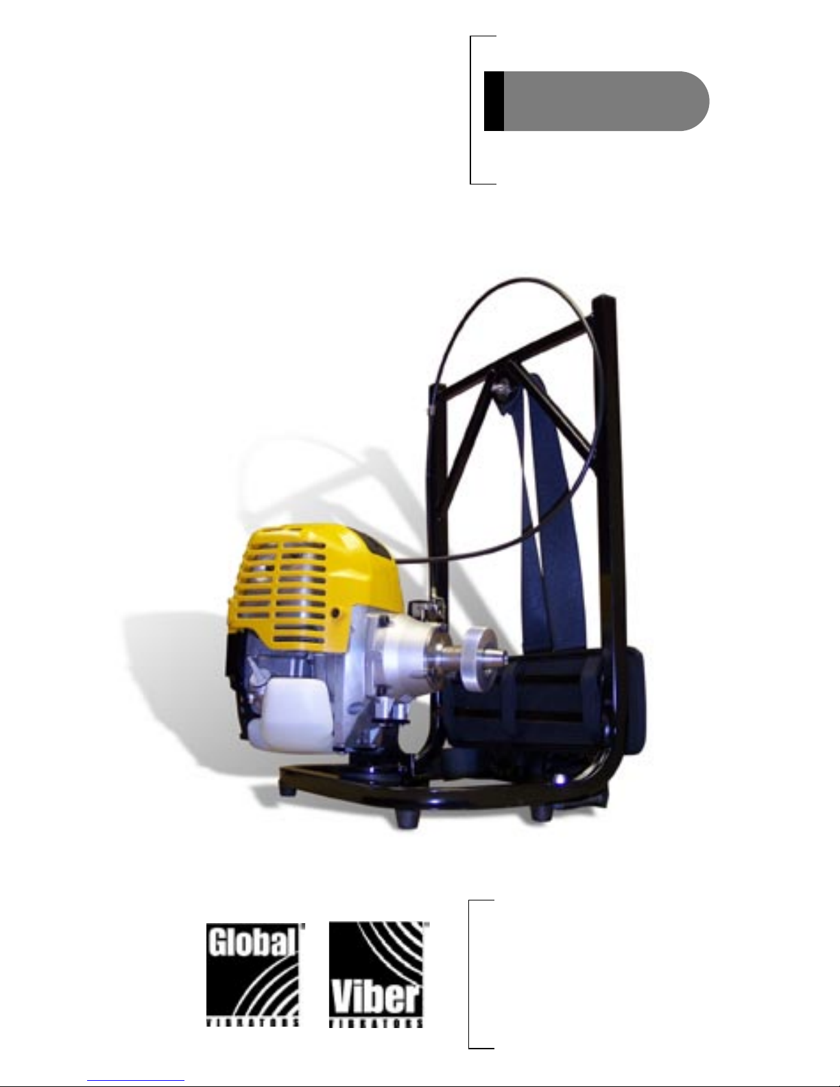
Mini Backpack
Operating Instructions
INTERNAL CONCRETE VIBRATOR
PORTABLE GASOLINE POWERED BACKPACK
VMG-1750BP
SAFETY OPERATION INSTRUCTIONS
Your safety and the safety of the people around you are very important. Operating the
Viber® model VMG-1750BP backpack concrete vibrator system in a safe manner is the duty
of every user.
Certain sections of this manual will contain such key words as DANGER, WARNING and
CAUTION. When you see any of these key words in the manual, please read the information following the key word very carefully.
DANGER, WARNING: Not obeying the instructions followed by these signal words may
lead to death or injury of the operator or those around him.
CAUTION: Not obeying the instructions following this signal can lead to personal injury
or damage to the equipment.
Before you use the VMG-1750BP please read through the entire set of operating instructions
and the Robin owner’s manual provided with each new unit. Both pieces of literature pro-
vide very important information about safety.
CAUTION
DANGER
WARNING
NOISE / SOUND
Hearing protection must be worn.

TABLE OF CONTENTS
I. INTRODUCTION
The Smart Parts
TM
System
Safety Precautions
II. ASSEMBLING YOUR INTERNAL CONCRETE VIBRATOR & QUICK DISCONNECT
III. OPERATION
IV. MOTOR MAINTENANCE
V. PARTS LIST
VI. PERFORMANCE SPECIFICATIONS
VII. TROUBLESHOOTING
VIII. Smart Parts
TM
SYSTEM RECOMMENDATIONS
I. INTRODUCTION
You have purchased a Viber® Gasoline Power Unit, the center of your Smart Parts
TM
Internal Concrete Vibrator system. The other system components include a Viber®
vibrator head and a Viber® reversible flexible drive.
POWER UNIT+ FLEXIBLE DRIVE+ HEAD = Smart Parts
TM
SYSTEM
You build the right Smart PartsTM System for your application by choosing from the
wide range of Viber® components including nine different power options, fourteen
different flexible drives, and twenty different vibrator heads. These components all
use identical fittings so that Viber® components are completely interchangeable.
Any flexible drive can be used with any of the power units and any of the heads.
See Section VIII for recommendations for selecting the best Viber® power unit, head
and flex drive for your application.
When properly used, your Smart PartsTM system will effectively compact concrete
to remove entrapped air, producing high quality concrete that is dense, strong,
durable, and impermeable.
1.
1. Inspect the vibrator system for damage. Never use a damaged vibrator.
2. Have all components of the vibrator system received proper maintenance?
VMG Gasoline Motors: Clean air filter every 25 hours and change engine
oil after every 50 hours of operation. Refer to the Robin Owner’s Manual for a
complete maintenance schedule.
Flexible Shafts: Re-grease core after every 50 hours of use or if core rattles excessively.
Vibrator Head: Monitor bearings. Viber® heads require no lubrication.
3. Are all vibrator system connections tight? Apply Teflon® tape to the casing threads,
before attaching the head, to give a watertight connection.
4. Do you have the proper fuel? Use unleaded gasoline with a pump octane rating of 86
or higher.
5. Check oil level in engine.
II. Assembling Your Internal Concrete Vibrator
& Quick Disconnect
The VMG-1750BP Gasoline Power Unit comes fully assembled except for the throttle control. Mount the throttle control, using the two screws provided, to the holes
located on the lower left side of the frame (when facing the backpack frame from
the rear, engine side). Orient the control so the black knob points outward, FAST is
at the top, and STOP is at the bottom.
All Viber® system components are interchangeable. All flexible drives (cores and
casings) can be used to attach any head to any power unit. For optimum performance and wear consult your Smart Parts™ SYSTEM GUIDE or the table in SECTION
VI for the best combination of components.
1. Attach the flexible drive (casing with lubricated core installed) to the power
unit. The VMG-1750BP comes with a quick disconnect for attaching flexible
drives to the power unit. To attach a quick disconnect drive fitting to the flex
drive, first apply a layer of Teflon® tape to the casing threads, add fitting and
turn it clockwise to tighten. Use a small pipe wrench or channel locks to be
sure the connection is tight. (If you do not have an assembled flex drive, the
core must be lubricated before installing it in the casing. Run the core
through a handful of Viber® Core Grease as it is inserted into the core.
Attach the end of the casing, where the core was inserted, to the quick
disconnect drive fitting.)
2.
CAUTION
CHECK YOUR EQUIPMENT
WARNING
Always be sure the gasoline power unit’s ignition switch is in the “off”
position before assembling or disassembling your system.
WARNING
NEVER attempt to change flexible drives while the engine is running

2. Place the flexible drive with installed quick disconnect fitting up to the quick
disconnect on the motor drive. Be sure the core engages in the motor drive.
Turn the large hand nut counter clockwise until tight (hand nut has left
hand threads to insure it will remain tight while operating the system).
3. Before attaching the head, check the length of core
extending from the head end of the flex drive. If this
length is greater than 2-3/4”, twist the core while
pushing it into the casing to make sure it is fully seated
in the motor. If the exposed core is greater than 2-3/4”
when it is fully seated in the motor it may bind and
cause damage to the core, casing, or head. Do not use
the system. Contact your dealer or Global Manufacturing at 1-800-551-3569.
4. To attach the head to the flex drive, be sure the core engages the drive
coupling in the head. First apply two layers of Teflon® tape to the casing
threads then tighten the head in a clockwise direction. Use a crescent wrench
on the machined flats on the head and channel locks or a small pipe wrench
on the casing fitting to make sure the connection is secure.
5. Use only fresh unleaded gasoline with a pump octane rating of 86 or higher.
Do not over fill tank.
III. Operation
3.
Do NOT leave out the Teflon® tape! It is required to provide a watertight
seal between the various components of your vibrator system and pre-
vents the connections from coming loose during operation. If Teflon®
tape or a similar sealant is not used, the components can be damaged by water that penetrates this connection, or the components can come apart and be lost in the concrete.
CAUTION
WARNING
Improperly maintaining the engine, or failing to correct a problem before
operation, could cause malfunction in which you could be seriously
injured.
Always perform an inspection and correct any problems found before starting engine.
WARNING
Always wear ear & eye protection, gloves and heavy boots when operating the backpack system

Refer to the Robin Engine owner’s
manual supplied with your
VMG-1750BP for engine
maintenance schedules and
detailed operating instructions.
To start the VMG-1750BP Gasoline Power Unit:
1. Remove any accumulated dirt or debris, especially from around the muffler
and recoil starter.
2. Check that all shields and covers are in place and all nuts, bolts, and screws
are tight.
3. Inspect the throttle, engine kill switch, and swivel joint, where the engine is
attached to the frame, to make sure they are in working order.
4. Check the engine oil level. Add oil if necessary.
5. Check the air filter. A dirty air filter will restrict airflow to the carburetor,
reducing engine performance.
6. Be sure the tank is full with fresh unleaded gasoline with a pump octane
rating of 86 or higher. Do not over fill the tank.
7. Place the VMG-1750BP on an elevated surface high enough to allow the
operator to put on the unit easily after starting.
8. Pump the fuel bulb on the carburetor to ensure fuel is in the float bowl.
9. For a cold engine, move the choke lever to the CLOSED position. To restart
a warm engine, leave the choke lever in the OPEN position.
10. Turn the red engine ignition switch to the ON position.
11. Place the throttle lever in the SLOW position.
12. Hold the VMG-1750BP unit in place with one hand. Pull the starter grip
lightly until you feel resistance, then pull briskly. Return the starter grip
SLOWLY to its initial position.
4.
CAUTION
Do NOT start the engine with the throttle lever in the FAST position. This
will engage the vibrator head as soon as the engine starts. Running the
vibrator head in air without regularly submersing it in the concrete will overheat the bearings.
DANGER
WARNING
This unit creates carbon monoxide gas when operating. Carbon Monoxide
is a colorless, odorless gas, which can cause injury or death.
Use only outdoors or where fresh air is constantly being introduced into the environment.

5.
13. If the choke lever was moved to the CLOSED position to start the engine,
gradually move it to the OPEN position as the engine warms up.
14. Place the VMG-1750BP unit on your back just as you would a backpack.
Place your arms through the spaces between the straps and the frame. Buckle
the chest strap. Adjust the shoulder and chest strap as needed.
15. You are now ready to vibrate concrete with your VMG-1750BP.
i. Use the black throttle lever on the left side of the frame to regulate the
vibrator speed. Keep in mind, that when consolidating concrete, faster is
not always better. The best performance might be obtained with the
throttle lever in a position below FULL throttle.
ii. The VMG-1750BP is equipped with a centrifugal clutch. By moving the
throttle to the SLOW position, the clutch will disengage allowing the
vibrator head to stop. Do not leave the vibrator head running in air.
RUNNING THE VIBRATOR HEAD IN AIR WITHOUT REGULARLY
SUBMERSING IT IN THE CONCRETE WILL OVERHEAT THE BEARINGS.
If the head is to be held out of the concrete, move the throttle lever to the
SLOW position to prolong bearing life.
iii. To stop the engine at any time, simply move the throttle lever to the SLOW
(fully down) position, and turn off Stop Switch.
Follow the guidelines below when using your Viber® Internal Concrete Vibrator
for consolidating concrete:
1. DO NOT leave the vibrator running in air. Totally submerse the vibrator
head in the concrete. This cools the bearings. Running the vibrator in air
without regularly submersing it in the concrete will overheat the bearings.
2. Avoid making sharp bends in the flexible shaft.
3. Make sure you can see the concrete surface. Use lighting if necessary.
4. Place the concrete in layers no deeper than the length of the vibrator head
plus 4-6”. Layers should not exceed 18-20”, otherwise the weight of the
concrete will prevent the entrapped air from escaping.
5. Keep the vibrator head at least 3-4” from the forms. It can damage them
causing surface defects in the concrete.
6. Do not allow the vibrator head to touch reinforcements, such as rebar.
Vibration can break the bond between the reinforcement and preceding
layers of stiffened concrete.
WARNING
The backpack system must be worn on the operators back for it to func-
tion properly. Do not attempt to operate the vibrating head while the
backpack is not being worn.
IMPORTANT
To stop the engine at any time, turn engine stop switch to “off”.
WARNING
When putting on the backpack, lift the unit by bending your knees. Do
not lift with your back.

6.
7. Let the vibrator head penetrate to the bottom of the layer as quickly as
possible under its own weight.
8. Keep the vibrator head vertical to minimize voids and enhance the release of
entrapped air. For shallow flat slabs, lay the vibrator head horizontally and
drag it through the concrete.
9. Withdraw the vibrator head slowly. Be sure concrete fills in behind leaving
no hole. Do not attempt to “stir” the concrete.
10. Use repeated placements of the vibrator in a systematic pattern to be sure the
entire surface has been vibrated. The area of action can be observed by noting
how far from the vibrator head bubbles appear on the surface. Placements of
the head should insure overlapping of the areas of action.
11. When compacting concrete placed on a previously compacted layer, push the
vibrator 4-6” into the lower layer. Move the vibrator up & down for 5-15
seconds to “knit” the two layers together.
12. Avoid placing the concrete in “heaps”. If it is necessary to flatten a heap,
insert the vibrator head around the perimeter of the heap using as many place ments as necessary.
13. Consolidation is complete when no new bubbles come to the top, a glistening
layer of mortar covers the concrete surface, and the “whine” of the motor
indicates that the vibrator speed has leveled off.
14. Clean all vibrator parts immediately following each use.
IV. Motor Maintenance
Routine monthly maintenance is recommended unless the power unit is used for multiple
shifts per day or in harsh environments (heavy dust, snow, sand, etc.). Refer to the Robin
Engine Owner’s Manual provided with your VMG-1750BP for details on performing engine
maintenance.
1. Engine Oil (SAE10W-30, API SJ): Check before each use. Change after the
first 10 hours of use and every 50 hours there after. Change every 25 hours in
high ambient temperatures.
2. Air Filter: Check before each use. Clean every 25 hours or more frequently
if used in dusty areas.
3. Spark Plug: Clean and adjust gap every 25 hours. Replace every two years.
4. Quick Disconnect: Require no lubrication and no routine maintenance. To order
additional quick disconnect drive fittings or for other replacement parts, contact your
dealer or Global Manufacturing at 1-800-551-3569.
DO NOT place anything on top of the motor.
DO NOT stand on the backpack frame or engine.
ALWAYS store the unit with its engine upright and the base on a flat level surface.
Do not store the unit on its side. Oil or gasoline may leak as a result. Leaking oil or gasoline is toxic and a fire hazard.
For long-term storage, it is recommended that the gasoline tank be drained and the engine
operated until the remaining fuel is consumed.
CAUTION

V. Parts List
7.
Part # Part Description

8.
VI. Smart Parts
TM
System Recommendations
To select the proper head and drive length to use with the VMG 1750BP for your
application refer to the table below:
1 2 3
Application Slump Space Limitations Head Diameter
Block Walls & Small Diameter Fills:
Plastic and flowing concrete for very thin
members & walls & confined places.
>3” 2.5” x 2.5”
7/8”
VH-14
Thinnest Prestressed Sections: Plastic
and flowing concrete for very thin members
& walls & confined places.
>3” 3” x 3”
1”
VH-16
Thin Prestressed Sections: Plastic
concrete in thin walls, columns, beams,
precast piles, thin slabs, and along construction joints.
3-5” 3.25” x 3.25”
1-1/4”
VH-20
Thin Wall Sections & General Use:
Plastic concrete in thin walls, columns,
beams, precast piles, thin slabs, and along
construction joints.
3-5” 3.5” x 3.5”
1-1/2”
VH-24
1-3/4”
VH-28-PH
Polly Head
General Use: Plastic & stiff plastic concrete in general construction such as walls,
columns, beams, pre-stressed piles, and
heavy slabs.
2-4” 3.75” x 3.75”
1-3/4”
VH-28
2”
VH-32-PH
Polly Head
Shallow Pours: Plastic & stiff plastic concrete in slabs and other shallow pours less
than 12” thick.
2-4” 4” x 4”
2-1/8”
VH-34-SP
2-3/8”
VH-38-SP
Polly Head
ICF Applications: Plastic and flowing
concrete for very thin members & walls &
confined places where insulated concrete
forms are used.
> 4” 2.5” x 2.5”
7/8”
VH-14-LF
1 - Find the description in column 1 that matches your application.
2 - Use column 2 to adjust for any size restrictions due to reinforcements, such as rebar,
or other limiting structures.
3 - Column 3 gives the diameter of the vibrator head needed.

9.
4 5
Power Unit
Flexible Drive Length (Feet)
1 3 5 7 10 14 21 28* 35*
VMG-1750 BP
x x x x x x
VMG-1750 BP
x x x x x x
VMG-1750 BP
x x x x x x
VMG-1750 BP
x x x x
VMG-1750 BP
x x x x
VMG-1750 BP
x x x x
VMG-1750 BP
x x x x x x
7’ or longer
recommended
7’ or longer
recommended
7’ or longer
recommended
7’ or longer
recommended
7’ or longer
recommended
7’ or longer
recommended
7’ or longer
recommended
4 - Select the power unit desired from column 4. VMG-1750BP is a 1.6 hp backpack
mounted gasoline engine. Electric and pneumatic power units are also available.
5 - Find the core and casing length desired in section 5. A small diameter (7/8”) casing is
available in all sizes for use with the 7/8” head.
* Note: 28’ and 35’ flex drives require coupling two shorter drives together. Flex drive
couplers are available in both standard and small diameter models.
not
recommended
not
recommended
not
recommended

10.
1750BPM_07/06
VII. Performance Specifications
• Centrifugal Clutch allows the operator to stop the vibration simply by
adjusting the throttle lever to the SLOW position. This prolongs vibrator
head bearing life by preventing excess heat build up when the head is not
submersed in the concrete.
• Throttle Control allows the operator to obtain the best speed of vibrator for
the size of head and the type of concrete being worked. The unit can be used
right hand or left hand as needed.
• Standard Quick Disconnect makes it simple to remove or attach the flexible
drive without tools.
• Engine swivels 180° allowing the flexible drive to more easily push back
behind the operator as it is pulled from the concrete. Motor remains “tight”
so it does not move excessively as the operator changes positions.
• The Engine will operate in any position.
VIII. Troubleshooting
Call factory 1-800-551-3569
Engine: 4-cycle, 2.04 cu.in., 1.6 hp Robin Overhead Valve
Engine.
Fuel: Standard Unleaded Gasoline, 86 octane or
higher. 0.17 US gal. Approximately 2 hours of
use per tank of gasoline.
Oil: SAE 10W-30, API SF, 0.1 US qt.
Head Size: Will drive all size internal concrete vibrator
heads up to 2-1/8” in diameter with any
flexible drive length up to 21’.
Speed: Transmission provides drive speed of 9,000 11,000 rpm with any size vibrator head up
to up to 1-3/4” in.
Other Features: The VMG-1750BP also provides the following
features:
 Loading...