

Global Manufacturing Quiet Thunder QT2-40X, Quiet Thunder QT2-80X, Quiet Thunder QT2-130X, Quiet Thunder QT2-100X Operating Instructions Manual
Global Manufacturing, Inc
®
1801 East 22nd St
Little Rock, AR 72206
501.374.7416 TEL
501.376.7147 FAX
800.551.3569 FREE USA & CANADA
GlobalManufacturing.com
®
QT2-80-130X_01/04/18
Copyright © 2018 Global Manufacturing, Inc.
Operating
Instructions
Models
Single Phase
115 Volt - 60 Hertz
QT2-40X
QT2-80X
QT2-100X
QT2-130X
VIBRATORS

Global Manufacturing, Inc ® 800.551.3569
Toll Free USA & Canada
1801 East 22nd St 501.374.7416
Tel
501.376.7147
Fax
Little Rock, AR 72206 USA www.GlobalManufacturing.com
2
• Follow wiring and installation wiring instructions.
• A licensed electrician should adhere to all electrical codes when wiring three phase
and direct wired single phase vibrators.
• Take amperage and voltage readings upon completion of installation. See page 9 for
run and start amp draws for each vibrator and page 21 for more information on
voltage drops.
• High amperage reading means something is wrong and the vibrator may be damaged
or not mounted properly. Do not operate a vibrator that pulls high amps.
• For single-phase, use properly grounded 3-prong receptacle and do not use an
extension cord without knowing the voltage drop in order to use the correct gauge
size. See page 21 for instructions on how to calculate what size of extension cord
you should use.
• Make sure all electrical connections are secure and will not vibrate loose.
• Follow all mounting instructions.
• Boltvibratortoaatsurface,acrossalongverticallyorientedchannelironushto
the outside of the hopper wall.
• Contact factory if you are unable to closely follow all installation instructions or if
amperage readings are high.
• Attach a safety cable or chain from vibrator to an independent stronghold.
• Prior to use, check vibrator for damage (twisted unit, cracked junction box, loose
wires, missing end covers, etc.) Do not operate a damaged vibrator.
• Maximumambientoperatingtemperatureis104˚F(40˚C).
• Do not mount electrical control boxes onto structure (bin/hopper) wall to be vibrated.
• Do not operate vibrators when structure is empty.
• Do not operate vibrators when gate is closed or conveyor is stopped unless
consolidation of material is desired.
• Wear ear protection for 90+ decibel levels.
• Do not operate vibrators without side covers.
• Always disconnect electricity before maintenance.
• Follow OSHA regulation Section 1910.145 for lockout program.
SAFETY PRECAUTIONS
Global Manufacturing, Inc ® 800.551.3569
Toll Free USA & Canada
1801 East 22nd St 501.374.7416
Tel
501.376.7147
Fax
Little Rock, AR 72206 USA www.GlobalManufacturing.com
3
OPERATION
These electric vibrators are built for
continuous duty, however the vibrators
may be cycled on and off for intermittent
duty. The minimum time between
consecutive starts is two (2) minutes.
Each time the vibrator starts it draws high
amperage, therefore allow vibrator to cool
or run for two minutes before starting
again.
Do not operate the vibrator on an empty
hopper. The vibration will vibrate the
hopper and the vibrator causing damage
if no bulk material is present. When the
vibrator is mounted rigidly the vibration will
pass through the structure and resonate
the material inside the hopper.
Operate vibrators when discharge gates
are open unless compaction of material
is d esired . The vibrator should appear
motionless.
INSTALLATION
The key to successful vibration is the proper
installation of the vibrator.
The axis of rotation of the eccentric
weights, which are found on the end(s) of
the motor shaft, should rotate toward the
desireddirectionofmaterialow.Inhopper
applications, the weights should rotate
towards the bin wall and down. The shaft of
the vibrator should ideally be in a horizontal
position to prolong bearing life.
Guidelines for the mounting industrial
vibrators:
QT2-40X, QT2-80X, QT2-100X, QT2-130X
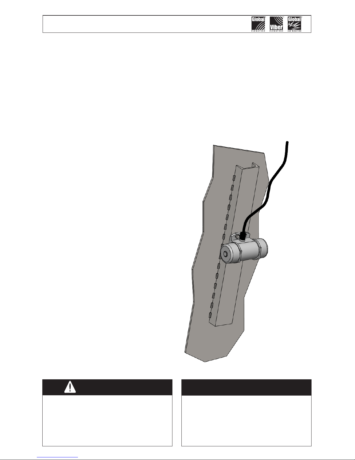
Single Phase models: Mount vibrator with
the power cord facing upwards.
Do not mount the vibrator directly
to the structure wall. Use a channel
iron stiffener for proper mount
rigidity and as the transducer of
the vibrational energy.
Caution!
The key to successful vibration is a proper
mount because rotary vibration resonates
the material inside the structure. The
vibrator should appear motionless. There
should not be a large amount of motion
or noise. Follow the instructions on how to
mount the vibrator and you will get great
results.
Important!
The channel iron should be at least
two-thirds of the height of the
sloped portion of the hopper but
no greater than 10 feet (3 m).
Models
Single Phase
115 Volt - 60 Hertz
QT2-40X
QT2-80X
QT2-100X
QT2-130X
Global Manufacturing, Inc ® 800.551.3569
Toll Free USA & Canada
1801 East 22nd St 501.374.7416
Tel
501.376.7147
Fax
Little Rock, AR 72206 USA www.GlobalManufacturing.com
4
Channel Irons - How to Mount
The channel iron should be at least two-
thirds the height of the sloped portion of
the hopper, but not less than 6' (1.8 m)
or greater than 10' (3 m) in length. The
channel iron width should not be less than
the base width of the vibrator. However,
a mount plate of 3/4" (19.05 mm) thick,
sizedtotthefootpatternofthevibrator,
may be skip welded to the channel. 3/4"
plate thickness prevents warpage when
welding plate to channel. The mount plate
must allow the vibrator to sit FLAT on
the plate with no detectable rocking.
If the vibrator does not sit at, the plate
may be warped. Shim the vibrator prior to
mounting to compensate for any warping.
See Table on page 8 for recommended
channel iron and mount plate sizes.
DO NOT install more than one vibrator on
the same channel iron or use a channel
iron shorter than the recommended length.
Ashortchannelmayexthebinwall.
Attach the vibrator to the channel iron.
Stitch weld nuts to the back of the channel
iron or the channel iron may be drilled and
tapped to accept the mounting bolts. An
alternate method is to cut a second channel
iron slightly longer than the footprint of the
vibrator. Stitch weld the second channel
iron to the rst. Do not weld the ends.
Mount the vibrator to the second channel
iron.
Stitch weld the channel iron vertically
to the slope portion of the bin wall.
Weld 3 inches (7.5 cm), skip 1 inch (2.5
cm), weld 3 inches (7.5 cm), etc... Leave
1 inch (2.5 cm) un-welded on the ends
and corners. This allows the vibration to
dissipate out the ends of channel without
causing stress cracks to the hopper or bin.
By doing so, should the weld fail, the entire
mount will not fall off. Do not mount the
channel iron horizontally.
Secure the vibrator to the channel
iron using the 4 slotted holes with SAE
coarse thread ¼"-20 grade 8 plated
bolts with lock washers or an adhesive
such as Loctite
®
262. If the four round
holes are used for mounting use 10-24
grade 2 plated bolts with lock washers or
an adhesive such as Loctite® 262. A wider
channel iron is also needed with this bolt
pattern or use a mount plate as illustrated
above.Tighten bolts in a sequential process.
At least two passes are required in most
situations. Give all bolts the same torque
value. If Loctite
®
is not used, torque the
bolt after the vibrator has operated for a
few minutes and check tightness often.
If Loctite® is used do not torque the bolts a
second time as this will break the Loctite
®
bond.
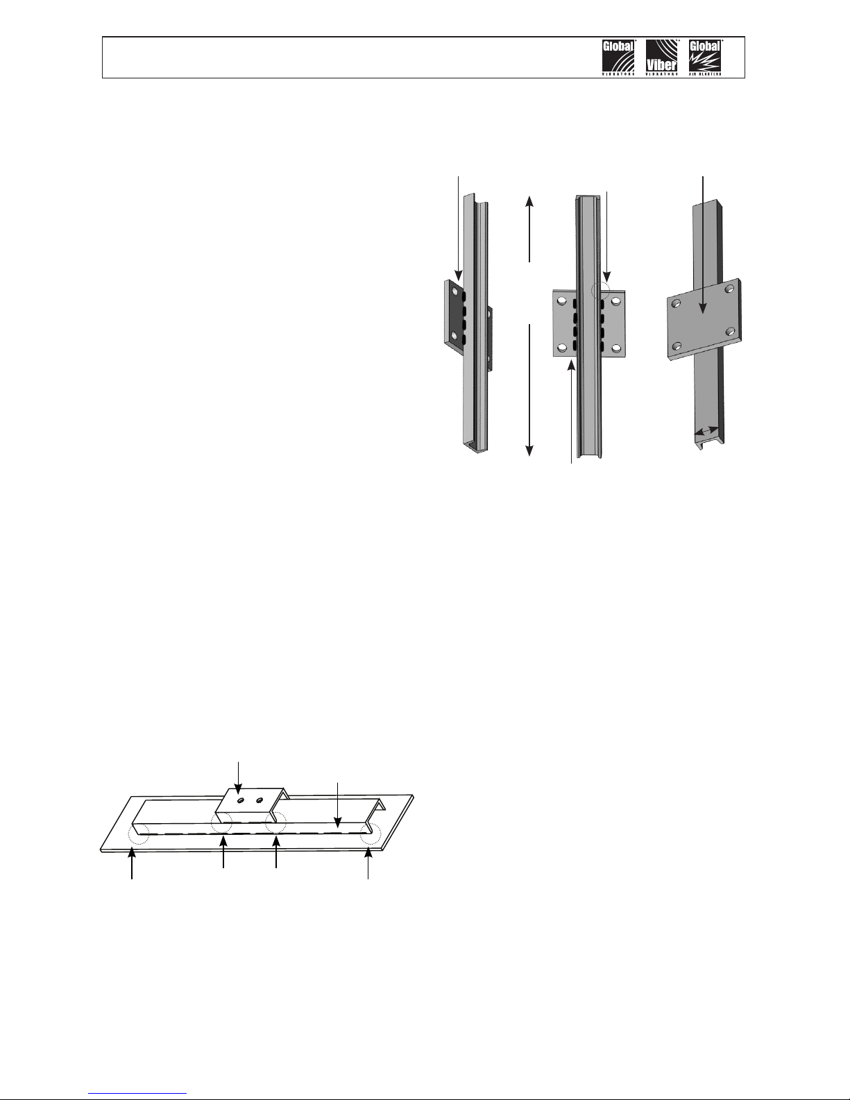
Channel Iron with Mount Plate
Channel Iron with Piggy-back Channel
Place vibrator
on top of
mount plate
Skip weld
along back
side of plate
Weld along the length of the
channel on back side of plate.
Do not weld across the width
of channel.
Length
of
Channel
Width of
Channel
Do not weld
the ends
of plate to
channel
Do not weld the ends of the channel iron.
This allows the vibrational force to “escape”.
Solid welded ends trap the force, which
can cause stress cracks.
Piggy-back
channel
Stitch weld
channel iron
Attach a safety cable to a stronghold (not
the channel iron mount), which is higher
than the mounted vibrator and capable of
holding the vibrator’s weight.

Global Manufacturing, Inc ® 800.551.3569
Toll Free USA & Canada
1801 East 22nd St 501.374.7416
Tel
501.376.7147
Fax
Little Rock, AR 72206 USA www.GlobalManufacturing.com
5
MOUNTING LOCATIONS
Single Vibrator
Install a channel iron stiffener on the
outside of the sloping wall 1/3 the distance
above the discharge opening.
Multiple Vibrators
Use more than one vibrator when the
diameter or width of any wall is greater
than 12 feet (3.66 m). Always mount the
vibrators on different planes.
Two Vibrators on Round or
Square Hoppers
Install channel iron stiffeners 180° apart.
Install one vibrator on the outside of the
sloping wall 1/3 the distance above the
discharge opening. Install the second
vibrator on the outside of the opposite
sloping wall 2/3 the distance above the
discharge opening.
Two Vibrators on Rectangular
Hoppers
Install channel iron stiffeners on opposite
sides of the long walls. Install one vibrator
on the outside of the sloping wall 1/3 the
distance from the discharge opening.
Install the second vibrator on the outside of
the opposite sloping wall 2/3 the distance
above the discharge opening. When only
one wall slopes, mount both stiffeners on
it. Equally space the stiffeners on the wall.
Place one vibrator 1/3 above the discharge
opening on one channel iron and the other
vibrator 2/3 above the bin's discharge
opening on the second channel.
Three Vibrators
Install channel iron stiffeners mounted
120°apart.Installtherstvibratoronthe
outside of the sloping wall 1/4 the distance
above the discharge opening. Install the
second vibrator on a separate channel iron
at 1/2 the distance above the discharge
opening. Install the third vibrator on the
remaining channel iron at 3/4 the distance
above the discharge opening.
H
⅓ of H
⅔ of H
⅓ of H
⅔ of H
H
¾
of
H
¼
of H
½
of H
⅔
of H
⅓
of H
⅔
of
H
⅔
of H
H

Global Manufacturing, Inc ® 800.551.3569
Toll Free USA & Canada
1801 East 22nd St 501.374.7416
Tel
501.376.7147
Fax
Little Rock, AR 72206 USA www.GlobalManufacturing.com
6
Width is more than 6’
¼ of Width
½ of Width
¼ of Width
Installation on Chutes and Flow Pipes
Mountchannelironstiffenersverticallyorinthedirectionofmaterialow.Centerthe
channel if the chute is less than 6 feet (1.83 m) in width. If the chute is greater than 6
feet in width, use two vibrators on separate channel irons. To maximize each vibrator’s
radiusofinuence;centereachchannelironineachhalfofthechute. Eachchannel
iron should be located ¼ of the chute width from the edge and ½ of the chute width
apart. (e.g. – for a chute 8' wide, the channel iron locations would be 2' from each edge
and 4' apart.) When chute thickness is less than 1/8", additional reinforcement may
be required.
Channel Iron Dimensions for Electric Vibrators
Vibrator
Model
Width
Minimum Web
Thickness
Minimum
Length
Weight Per
Length
inch inch feet lb/ft
mm mm mm kg/m
QT2-40X, QT2-80X,
QT2-100X, QT2-130X
3.0 .17 2 4.1
75 4 609 6.1
Make channel iron length at least 2/3 the height of the slope section of the bin
without exceeding 10' (3 M) in length.
Vibrator Bolts and Required Torque - Single Phase
Model Bolt Torque
QT2-40X, QT2-80X,
QT2-100X, QT2-130X
10-24 grade 2 plated bolts 4 lb-ft (5 N-m)
¼"-20 grade 8 plated bolts
for slotted holes
10 lb-ft (13 N-m)

Global Manufacturing, Inc ® 800.551.3569
Toll Free USA & Canada
1801 East 22nd St 501.374.7416
Tel
501.376.7147
Fax
Little Rock, AR 72206 USA www.GlobalManufacturing.com
7
WIRING ELECTRIC VIBRATORS
Only a qualified electrician should connect
an electric vibrator to a power source.
Using power of incorrect voltage or phase
or inadequate wire size will damage the
vibrator and void the manufacturer’s
warranty.
Always measure the amperage on
all legs of the supplied power after
installing the vibrator. If the amp
draw exceeds that specified on the
motor nameplate, turn off the vibrator
immediately. Operating an electric
vibrator with an excessive amp
draw will lead to premature motor
failure that is not covered by the
manufacturer’s warranty.
The cause for a high amp draw must be
determined and corrected before operating
the vibrator. Possible causes of high
amp draw:
1. a non-rigid mount
2. mount plate too thin
3. warped mount plate
4. low voltage (from power
source or due to inadequate
wiring or extension cord)
5. incorrect voltage
6. vibrator produces too much
force for application
It is recommended that the initial amperage
readings be recorded for future reference.
If you cannot determine the cause of
a high amp draw, Do Not Operate
the Vibrator. Cal l G l o bal Manufacturing
customer support at 1-800-551-3569.
When seeking customer technical support,
please provide the product serial number,
voltage and phase of the power source,
and the initial amperage readings. If
you periodically check the amperage, an
increase in the amp draw will indicate the
onset of a problem such as decreased or
fluctuating voltage, loose mount bolts, or
a loss in rigidity of the mount. High amp
readings should never be ignored.
These Global vibrators do not have dual
voltage motors. They are designed and
wired at the factory for 115-volt single
phase power. They cannot be rewired
for a different voltage.
Maximum Allowable Current
Draw:
115 Volt - Single Phase
Model
Amps
Max
Run
QT2-40X, QT2-80X,
QT2-100X, QT2-130X
.46
LEADING CAUSES OF
ELECTRIC VIBRATOR FAILURE
1) Low Voltage:
Possible failure point is low voltage caused
by high starting current. An electric vibrator
will take 2 to 3 seconds to reach full running
speed. During this starting period, the
vibrator draws more current than it draws at
full running speed. The high starting current
may cause the voltage to sag or drop below
80% of the rated voltage when measured
at the vibrator. If inadequate voltage is
provided initially, a voltage drop will cause
problems. Low voltage may prevent the
vibrator from reaching its rated speed,
and cause the motor to continue to draw
high starting current for a prolonged period
until it burns up. The electric power circuit
must be able to handle the high starting
current without dropping below 80% of the
rated voltage. The most common problems
are using a long extension cord with the
wire gauge undersized or an undersized
transformer which cannot handle the high
amp draw on start up.

Global Manufacturing, Inc ® 800.551.3569
Toll Free USA & Canada
1801 East 22nd St 501.374.7416
Tel
501.376.7147
Fax
Little Rock, AR 72206 USA www.GlobalManufacturing.com
8
2) Improper Mounting:
When an electric motor runs slower than
its rated speed, it will draw excessive
current and eventually burn up. A non-
rigid mount hinders the vibrator from
reaching full running speed. In screen and
feeder applications, the vibrator may get
“trapped” in the resonant frequency of the
structure and not have enough power to
reach full running speed. Adjust the springs
if possible to change resonant frequency.
Improper mounting of the electric vibrator
will cause it to fail.
3) Excess Force:
If vibrator produces too much force and
causesexingofthemountofbinwall,the
vibrator will not reach full speed, will pull
high amps and fail.
The weights on this vibrator can be adjusted
to produce force outputs from 15 pounds of
force to 132 pounds of force. There are two
methods for adjusting the weights. Using
the Weight Rotation Method individual
weights are rotated 180 degrees to reduce
the force output from the maximum setting
where all nine weights are in alignment
(none rotated). The configuration of the
weights must be the same on both
ends of the vibrator shaft. See the
possible weight configurations and their
resulting force output in the table below.
Using the Weight Removal Method the
force is reduced from the maximum by
removing the same number of weight discs
from each side. When a weight disc is
removed it must be replaced with a standard
flat washer of the same thickness as the
weight disc. As before, the configuration
of the weights must be the same on both
ends of the vibrator shaft. See the possible
weight configurations and their resulting
force output in the table below.
WEIGHT SETTING ADJUSTMENTS

Global Manufacturing, Inc ® 800.551.3569
Toll Free USA & Canada
1801 East 22nd St 501.374.7416
Tel
501.376.7147
Fax
Little Rock, AR 72206 USA www.GlobalManufacturing.com
9
1 Set Of Weight Contributes 0.0433 Lb-In Of Unbalance and 15 lb-f
Weight Rotation Method For Setting Force Output:
Model
Factory Weight Unbalance Force
Setting Configuration lb-in lb-f Comments
1 SET 0.0433 15
QT2-130X-1 9-0 0.3893 132 All 9 weights in same orientation
QT2-100X-1 8-1 0.3028 102 One of 9 weights rotated 180 degrees
QT2-080X-1 7-2 0.2163 73 Two of 9 weights rotated 180 degrees
QT2-040X-1 6-3 0.1298 44 Three of 9 weights rotated 180 degrees
5-4 0.0433 15 Four of 9 weights rotated 180 degrees
Weight Removal Method For Setting Force Output:
Model
Factory Weight Unbalance Force
Setting Configuration lb-in lb-f Comments
QT2-130X-1 9-0 0.3893 132 All nine weights in same orientation
8-0 0.3460 117 1 weight removed & replaced with flat washer
7-0 0.3028 102 2 weights removed & replaced with flat washers
6-0 0.2595 88 3 weights removed & replaced with flat washers
5-0 0.2163 73 4 weights removed & replaced with flat washers
4-0 0.1730 58 5 weights removed & replaced with flat washers
3-0 0.1298 44 6 weights removed & replaced with flat washers
2-0 0.0865 29 7 weights removed & replaced with flat washers
1-0 0.0433 15 8 weights removed & replaced with flat washers

Global Manufacturing, Inc ® 800.551.3569
Toll Free USA & Canada
1801 East 22nd St 501.374.7416
Tel
501.376.7147
Fax
Little Rock, AR 72206 USA www.GlobalManufacturing.com
10
Performance Data
VIBRATOR
MODEL
Unbalance
Speed
Force
Available
Voltages
Amp
Draw
Output
Power
Min Med Max Min Med Max Run
lb-in lb-in lb-in
rpm
lb lb lb
volts amps hp
kg-mm kg-mm kg-mm kN kN kN
QT2-40X
0.04 0.09 0.13
3450
15 29 44
115
0.46
0.05
0.5 1.0 1.5 0.07 0.13 0.20
QT2-80X
0.04 0.13 0.22
3450
15 44 73
115
0.46
0.05
0.5 1.5 2.5 0.07 0.20 0.33
QT2-100X
0.13 0.22 0.30
3450
44 73 102
115
0.46
0.05
1.5 2.5 3.5 0.20 0.33 0.46
QT2-130X
0.22 0.30 0.39
3450
73 102 132
115
0.46
0.05
2.5 3.5 4.5 0.33 0.46 0.59
Each model is factory set at the maximum force-pound value given in the table above unless requested otherwise. All models come with full set of
weights that can be adjusted from 15 lb-f to 132 lb-f in 14.6 lb-f increments.
Motor casing in aluminum.
Weight covers in 304 stainless steel.
Operating Temperatures: -4°F - 104°F (-20°C - 40°C).
Insulation Class F (275°F or 135°C).
Mechanical protection = IP 65 (Total protection against dust and low pressure water).
Designed for continuous duty with 100% centrifugal force.

Global Manufacturing, Inc ® 800.551.3569
Toll Free USA & Canada
1801 East 22nd St 501.374.7416
Tel
501.376.7147
Fax
Little Rock, AR 72206 USA www.GlobalManufacturing.com
11
QT2-40X or 80X or 100X or130X Series - Electric Vibrator Dimensions
Weight
A B C D E F G
H
I J
K
Total
Length
Total
Height
Foot
Width
Body
Width
Foot
Thickness
Rd Bolt Hole
Separation
Length
Rd Bolt Hole
Separation
Width
Round
Bolt Hole
Size
El Bolt Hole
Separation
Length
El Bolt Hole
Separation
Width
Elongated
Bolt Hole
Size
lb in in in in in in in in in in in
kg mm mm mm mm mm mm mm mm mm mm mm
4.9 6.77 2.95 4.33 2.93 0.35 2.36 3.35 .236 1.00-1.57 3.62 .256
2.0 172 75 110 74 9 60 85 6.0 25-40 92 6.5
C
B
D
A
F
K
J
H
I
G
E

Global Manufacturing, Inc ® 800.551.3569
Toll Free USA & Canada
1801 East 22nd St 501.374.7416
Tel
501.376.7147
Fax
Little Rock, AR 72206 USA www.GlobalManufacturing.com
12
Voltage & Amp Readings must be done prior to operating Vibrator
Important!
Typically, motors can tolerate a 10% drop
in voltage while running. Since start-up
lasts only 1 to 2 seconds, a 20% drop
should be tolerated for that short period
of time when the motor is pulling higher
amps. The best way to check this is to
use a voltage meter at the motor. Check
minimum voltage during start-up and
the running voltage once the motor has
reached its running speed. Assuming 120
volt motor, it needs at least 96 volts during
start-up, and once the motor reaches its
operational speed it needs 108 volts. When
sizing an extension cord one must be
careful because the extension cord is only
one source of voltage drop. The power
source might also uctuate. It is best to
assume the power source could uctuate
by 5%. Thus the 120 volt source might at
times only provide 114 volts. Therefore,
the extension cord cannot cause more than
a 15% voltage drop during start-up and
only a 5% drop after reaching operational
speed. With a 100' 14AWG copper wire
extension cord, one would get a 20.231
voltage (16.86%) drop during motor startup when pulling 39 amps. This means the
voltage at the vibrator might be as low as
93.77 volts, too low for proper starting.
Once the vibrator reaches full speed it
pulls only 2.6 amps. The voltage drop here
would be 1.349 volts leaving 112.65 volts,
which should be sufcient to keep the
unit running. HOWEVER, the low voltage
during start-up causes excess heat that
degrades the motor insulation. This effect
is cumulative, so even though the vibrator
starts the rst,second, orthird time the
damage done by low voltage is building.
Eventually the insulation fails and the
motor will burn up. In this example only the
start windings will fail prematurely, which
will leave the vibrator inoperable.
To further explain voltage drops
pertaining to the above example:
If a 12AWG cord is used the voltage drops
will be:
Start-up=12.733 volts giving a net of 101.3
volts
Run=0.849 volts giving a net of 113.2 volts
This extension cord would be adequate.
If a 10AWG cord is used the voltage drops
will be:
Start-up=8 volts giving a net of 106 volts
Run=0.534 volts giving a net of 113.5 volts
This extension cord would be better.
There is a good website with a nice voltage
drop calculator. If you have the wire size,
length, power source voltage, and amp
draw it will calculate the voltage drop.
http://www.powerstream.com/Wire_Size.
htm
YOU MUST ALSO CHECK THE AMP
DRAW. It the amp draw exceeds the
manufacturer’s specications then the
vibrator is probably not properly mounted.
The mount may not be level or lack
proper rigidity. Please follow the mounting
instructions in this manual.

Global Manufacturing, Inc ® 800.551.3569
Toll Free USA & Canada
1801 East 22nd St 501.374.7416
Tel
501.376.7147
Fax
Little Rock, AR 72206 USA www.GlobalManufacturing.com
13
Problem Probable Cause Solution
Excessive
noise
Vibrator mount is not rigid.
Make sure mount is rigid and
the vibrator is perpendicular
to channel iron See pages
6 - 8. Tighten all bolts. Check
for cracked welds or broken
housing.
Vibrator will
not start
Single phase circuit breaker
(purchased separately) is
tripped.
Correct the problem that
caused the overload. Reset
breaker. See pages
9 & 14.
Circuit is interrupted. Make sure all leads are “hot”.
Vibrator
runs hot or
overheats
Excessive
Current
(Check voltage
and amp draw
on start-up
and on run.)
Vibrator mount is not rigid
Make sure mount is rigid. See
pages 6 - 8. Tighten all bolts.
Check for cracked welds or a
broken housing.
Voltage is low. Conductor
gauge or extension cord is
inadequate or too small.
Use a heavier gauge when
using extension cords or
conductor. See page 21 for
voltage/amp information and
how to size an extension cord.
Stop-Start time intervals too
short. The motor is restarted
quickly again after stopping.
The time between start-ups
needs to be at least two
minutes. The amperage draw
at start-up is high and creates
heat. A two minute time delay
allows motor to cool down.
Ambient temperature is too
hot for vibrator.
Protect vibrator from ambient
temperature above 104°F
(40°C).
Mountingsurfaceisnotat
and motor is binding.
Check mount plate surface.
Mustbeat.Useshimsto
level the vibrator mount if
necessary.
Vibrator force output is
excessive for application.
Reduce force by adjusting
weights.
TROUBLESHOOTING
 Loading...