

Global Manufacturing Quiet Thunder QT2-40X, Quiet Thunder QT2-80X, Quiet Thunder QT2-130X, Quiet Thunder QT2-100X Operating Instructions Manual
Global Manufacturing, Inc
®
1801 East 22nd St
Little Rock, AR 72206
501.374.7416 TEL
501.376.7147 FAX
800.551.3569 FREE USA & CANADA
GlobalManufacturing.com
®
QT2-80-130X_01/04/18
Copyright © 2018 Global Manufacturing, Inc.
Operating
Instructions
Models
Single Phase
115 Volt - 60 Hertz
QT2-40X
QT2-80X
QT2-100X
QT2-130X
VIBRATORS

Global Manufacturing, Inc ® 800.551.3569
Toll Free USA & Canada
1801 East 22nd St 501.374.7416
Tel
501.376.7147
Fax
Little Rock, AR 72206 USA www.GlobalManufacturing.com
2
• Follow wiring and installation wiring instructions.
• A licensed electrician should adhere to all electrical codes when wiring three phase
and direct wired single phase vibrators.
• Take amperage and voltage readings upon completion of installation. See page 9 for
run and start amp draws for each vibrator and page 21 for more information on
voltage drops.
• High amperage reading means something is wrong and the vibrator may be damaged
or not mounted properly. Do not operate a vibrator that pulls high amps.
• For single-phase, use properly grounded 3-prong receptacle and do not use an
extension cord without knowing the voltage drop in order to use the correct gauge
size. See page 21 for instructions on how to calculate what size of extension cord
you should use.
• Make sure all electrical connections are secure and will not vibrate loose.
• Follow all mounting instructions.
• Boltvibratortoaatsurface,acrossalongverticallyorientedchannelironushto
the outside of the hopper wall.
• Contact factory if you are unable to closely follow all installation instructions or if
amperage readings are high.
• Attach a safety cable or chain from vibrator to an independent stronghold.
• Prior to use, check vibrator for damage (twisted unit, cracked junction box, loose
wires, missing end covers, etc.) Do not operate a damaged vibrator.
• Maximumambientoperatingtemperatureis104˚F(40˚C).
• Do not mount electrical control boxes onto structure (bin/hopper) wall to be vibrated.
• Do not operate vibrators when structure is empty.
• Do not operate vibrators when gate is closed or conveyor is stopped unless
consolidation of material is desired.
• Wear ear protection for 90+ decibel levels.
• Do not operate vibrators without side covers.
• Always disconnect electricity before maintenance.
• Follow OSHA regulation Section 1910.145 for lockout program.
SAFETY PRECAUTIONS
Global Manufacturing, Inc ® 800.551.3569
Toll Free USA & Canada
1801 East 22nd St 501.374.7416
Tel
501.376.7147
Fax
Little Rock, AR 72206 USA www.GlobalManufacturing.com
3
OPERATION
These electric vibrators are built for
continuous duty, however the vibrators
may be cycled on and off for intermittent
duty. The minimum time between
consecutive starts is two (2) minutes.
Each time the vibrator starts it draws high
amperage, therefore allow vibrator to cool
or run for two minutes before starting
again.
Do not operate the vibrator on an empty
hopper. The vibration will vibrate the
hopper and the vibrator causing damage
if no bulk material is present. When the
vibrator is mounted rigidly the vibration will
pass through the structure and resonate
the material inside the hopper.
Operate vibrators when discharge gates
are open unless compaction of material
is d esired . The vibrator should appear
motionless.
INSTALLATION
The key to successful vibration is the proper
installation of the vibrator.
The axis of rotation of the eccentric
weights, which are found on the end(s) of
the motor shaft, should rotate toward the
desireddirectionofmaterialow.Inhopper
applications, the weights should rotate
towards the bin wall and down. The shaft of
the vibrator should ideally be in a horizontal
position to prolong bearing life.
Guidelines for the mounting industrial
vibrators:
QT2-40X, QT2-80X, QT2-100X, QT2-130X
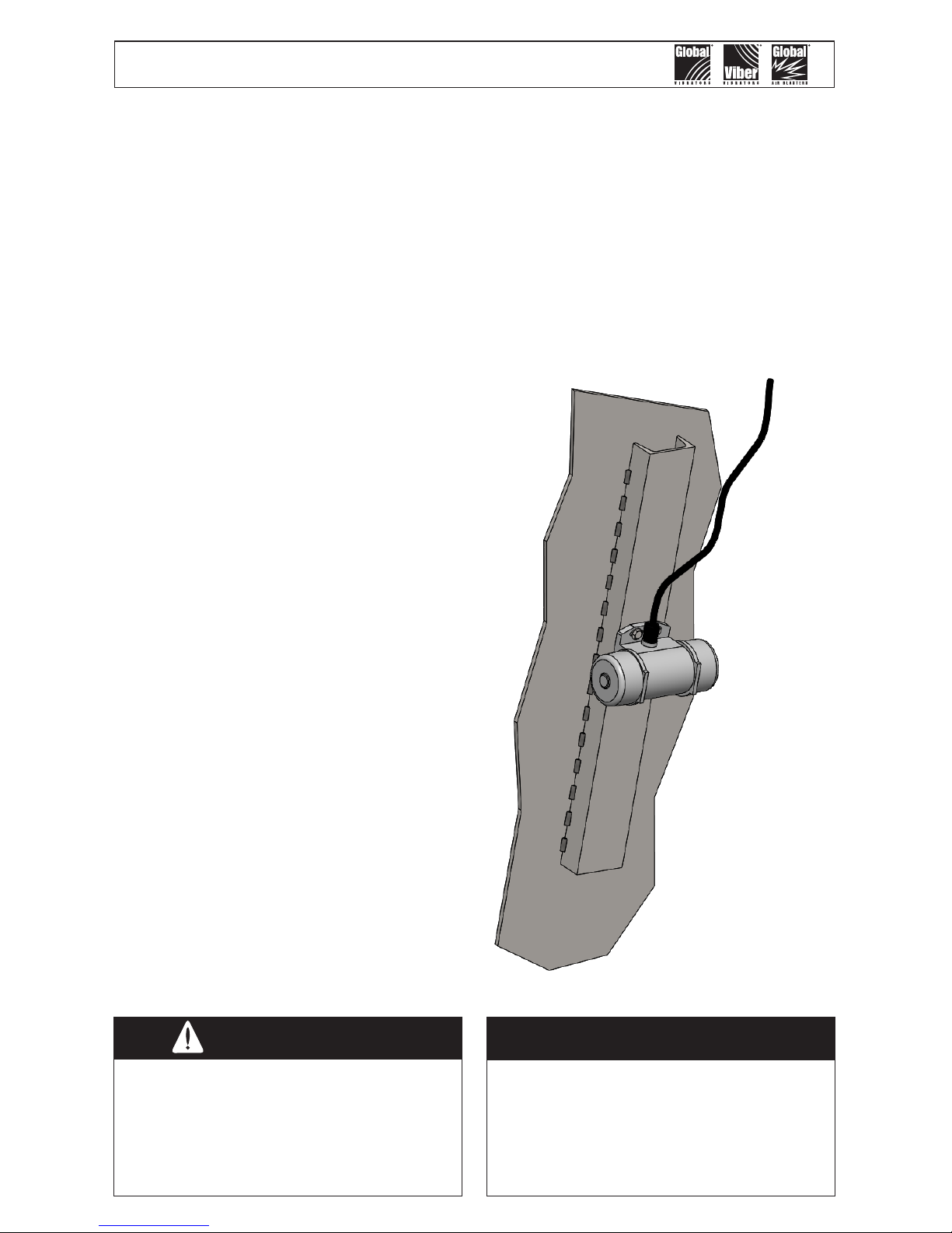
Single Phase models: Mount vibrator with
the power cord facing upwards.
Do not mount the vibrator directly
to the structure wall. Use a channel
iron stiffener for proper mount
rigidity and as the transducer of
the vibrational energy.
Caution!
The key to successful vibration is a proper
mount because rotary vibration resonates
the material inside the structure. The
vibrator should appear motionless. There
should not be a large amount of motion
or noise. Follow the instructions on how to
mount the vibrator and you will get great
results.
Important!
The channel iron should be at least
two-thirds of the height of the
sloped portion of the hopper but
no greater than 10 feet (3 m).
Models
Single Phase
115 Volt - 60 Hertz
QT2-40X
QT2-80X
QT2-100X
QT2-130X
Global Manufacturing, Inc ® 800.551.3569
Toll Free USA & Canada
1801 East 22nd St 501.374.7416
Tel
501.376.7147
Fax
Little Rock, AR 72206 USA www.GlobalManufacturing.com
4
Channel Irons - How to Mount
The channel iron should be at least two-
thirds the height of the sloped portion of
the hopper, but not less than 6' (1.8 m)
or greater than 10' (3 m) in length. The
channel iron width should not be less than
the base width of the vibrator. However,
a mount plate of 3/4" (19.05 mm) thick,
sizedtotthefootpatternofthevibrator,
may be skip welded to the channel. 3/4"
plate thickness prevents warpage when
welding plate to channel. The mount plate
must allow the vibrator to sit FLAT on
the plate with no detectable rocking.
If the vibrator does not sit at, the plate
may be warped. Shim the vibrator prior to
mounting to compensate for any warping.
See Table on page 8 for recommended
channel iron and mount plate sizes.
DO NOT install more than one vibrator on
the same channel iron or use a channel
iron shorter than the recommended length.
Ashortchannelmayexthebinwall.
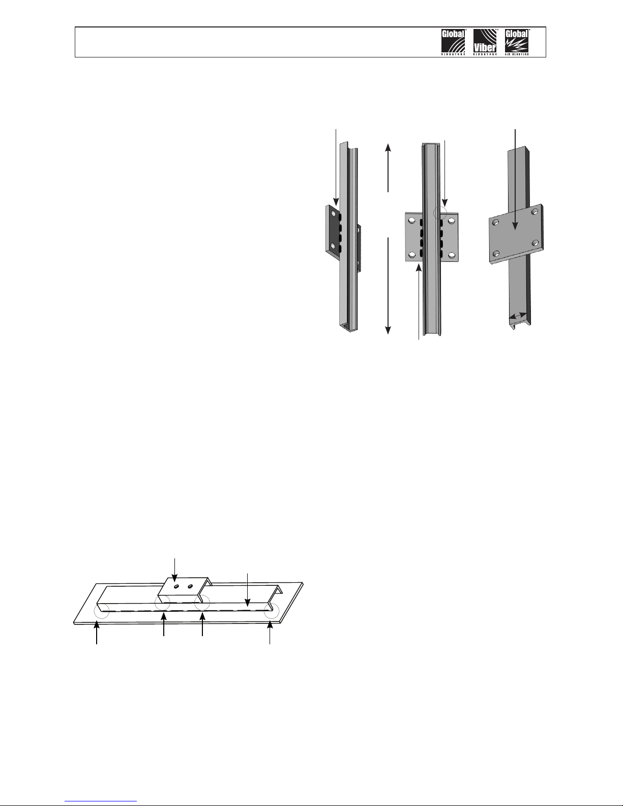
Attach the vibrator to the channel iron.
Stitch weld nuts to the back of the channel
iron or the channel iron may be drilled and
tapped to accept the mounting bolts. An
alternate method is to cut a second channel
iron slightly longer than the footprint of the
vibrator. Stitch weld the second channel
iron to the rst. Do not weld the ends.
Mount the vibrator to the second channel
iron.
Stitch weld the channel iron vertically
to the slope portion of the bin wall.
Weld 3 inches (7.5 cm), skip 1 inch (2.5
cm), weld 3 inches (7.5 cm), etc... Leave
1 inch (2.5 cm) un-welded on the ends
and corners. This allows the vibration to
dissipate out the ends of channel without
causing stress cracks to the hopper or bin.
By doing so, should the weld fail, the entire
mount will not fall off. Do not mount the
channel iron horizontally.
Secure the vibrator to the channel
iron using the 4 slotted holes with SAE
coarse thread ¼"-20 grade 8 plated
bolts with lock washers or an adhesive
such as Loctite
®
262. If the four round
holes are used for mounting use 10-24
grade 2 plated bolts with lock washers or
an adhesive such as Loctite® 262. A wider
channel iron is also needed with this bolt
pattern or use a mount plate as illustrated
above.Tighten bolts in a sequential process.
At least two passes are required in most
situations. Give all bolts the same torque
value. If Loctite
®
is not used, torque the
bolt after the vibrator has operated for a
few minutes and check tightness often.
If Loctite® is used do not torque the bolts a
second time as this will break the Loctite
®
bond.
Channel Iron with Mount Plate
Channel Iron with Piggy-back Channel
Place vibrator
on top of
mount plate
Skip weld
along back
side of plate
Weld along the length of the
channel on back side of plate.
Do not weld across the width
of channel.
Length
of
Channel
Width of
Channel
Do not weld
the ends
of plate to
channel
Do not weld the ends of the channel iron.
This allows the vibrational force to “escape”.
Solid welded ends trap the force, which
can cause stress cracks.
Piggy-back
channel
Stitch weld
channel iron
Attach a safety cable to a stronghold (not
the channel iron mount), which is higher
than the mounted vibrator and capable of
holding the vibrator’s weight.
 Loading...