

Global Manufacturing Ball Vibrators, BS-13, BS-16, BS-19, BS-10 Operating Instructions Manual
...
AIR BLASTERSVIBRATORSVIBRATORS
Ball Vibrators
Models
Operating Instructions
Pneumatic Ball Vibrators
BS-10 US-13
BS-13 US-19
BS-16 US-25
BS-19 US-38
BS-25
CS-19 DS-41
CS-25 DS-51
CS-35
CS
GlobalManufacturing.com
BV_07/14/14 - rev 2 - email version Copyright © 2014 by Global Manufacturing, Inc
DS
BS
Global Manufacturing Inc.
1801 East 22nd St
Little Rock, Arkansas 72206
501.374.7416 TEL
800.551.3569 TOLL FREE USA & CANADA
501.376.7147 FAX
®
US
Global Manufacturing, Inc ® 800.551.3569 TOLL FREE USA & CANADA
1801 East 22nd Street 501.374.7416 TEL 501.376.7147 FAX
Little Rock, AR 72206 USA www.GlobalManufacturing.com
A I R B L A STER SVIBRA T O R SVIBRA T O R S
Table of Contents Page
I. Introduction 2
II. Operation - Air Requirements 2
III. Installation Procedures 3 - 4
I V. Channel Irons - Size and Mounting 3
V. Mounting Locations 3 - 4
VI. Performance Data and Troubleshooting 5
VII. Dimensions 6
I. Introduction
For optimum performance, cycle the vibrator on and off. The vibrator acts as a friction reducer and once the bulk
solid is set into motion, gravity should do the rest. Do not operate the vibrator on an empty hopper as this may cause
structural damage to the hopper.
Vibrators should be operated only when discharge gates are open. Operating the vibrator with the discharge gate
closed will cause the material inside the structure to compact.
Vibration has two important elements – Frequency and Amplitude. Frequency is the speed (RPM) or the number of
vibrations per minute. It is controlled by the oil ow to a hydraulic vibrator or the air ow to a pneumatic vibrator.
Amplitude is the unbalance or amount of force produced by the eccentric weight. The faster the eccentric weights
turn the more force output generated. Force and frequency work together. It is not necessary to use a lot of force
when you adequate frequency.
SAFETY PRECAUTIONS
• Follow all installation instructions.
• Always use a safety cable or chain for support.
• Do not operate vibrators when structure is empty.
• Wear ear protection for 90+ decibel levels.
• Do not operate vibrator if there is a restriction to the exhaust port.
• Do not operate the pneumatic vibrators above 100 psi.
• Always operate pneumatic vibrator with a lter - regulator.
• Always disconnect air line before maintenance.
II. Operation - Air Requirements
Operate on ltered, regulated air between 20 and 80 PSI (1.36 to 5.44 Bar). An air regulator may be used to control
the vibrator speed. Adjust airow until material ow occurs. More air is not always better. Operating the vibrator at
higher pressures will reduce vibrator life.
Cycle the vibrator on and off. Ball vibrators can run continuously, but it is usually not necessary. Once the material
is set into motion, gravity should do the rest. Do not operate the vibrator on an empty hopper.
The vibrator should appear motionless. Vibrators should NOT shake the hopper wall or make an abundance of noise.
Vibrations pass through the structure and into the material.
Do NOT lubricate the ball vibrator. Lubrication is NOT required. Lubrication will collect dirt, impairing proper vibrator
operation.
2
Global Manufacturing, Inc ® 800.551.3569 TOLL FREE USA & CANADA
1801 East 22nd Street 501.374.7416 TEL 501.376.7147 FAX
Little Rock, AR 72206 USA www.GlobalManufacturing.com
A I R B L A STER SVIBRA T O R SVIBRA T O R S
III. Installation Procedures
Caution!
Do not mount the vibrator directly to the
structure wall. Use a channel iron stiffener
for proper mount rigidity and as the
transducer of the vibrational energy.
The key to successful
vibration is a proper mount
because rotary vibration
resonates the material
inside the structure, when
the vibrator is mounted
correctly. The vibrator
should appear motionless. There should not be
a large amount of motion
or noise.
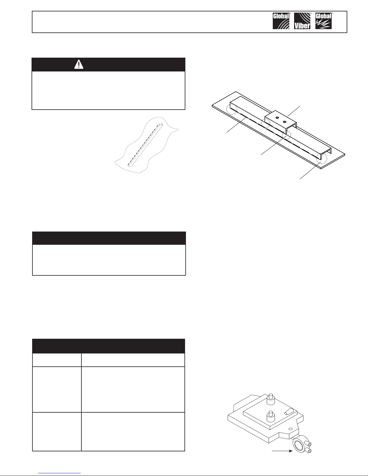
Stitch Weld the
Channel Iron
IV. Channel Irons - Size & Mounting
Important!
The channel iron should be at least 2/3
of the height of the sloped portion of the
hopper but no greater than 6 feet (1.83 m).
The channel iron should be at least two-thirds the height
of the sloped portion of the hopper, but not be greater
than 6 feet (1.83 m) in length. The channel iron width
should not be less than the base width of the vibrator.
See chart below for recommended channel sizes. DO
NOT install more than one vibrator on the same channel
iron or use a channel iron shorter than the recommended
length. A short channel may ex the bin wall.
Channel Iron Size Recommendation
Vibrator Channel Iron Size
Attach the vibrator to the channel iron. Stitch weld
nuts to the back of the channel iron or the channel iron
may be drilled and tapped to accept the mounting bolts.
An alternate method is to cut a second channel iron
slightly longer than the footprint of the vibrator. Stitch
weld the second channel iron to the rst. Do not weld
the ends. Mount the vibrator to the second channel iron.
Piggy-back
channel
Stitch weld
channel iron
Do not weld the ends of the channel
iron - this allows the vibrational force
to “escape”. Solid welded ends trap
the force which can cause stress
cracks.
Stitch weld the channel iron vertically to the sloped
portion of the bin wall. Weld 3 inches (7.5 cm), skip
1 inch (2.5 cm), weld 3 inches (7.5 cm), etc... Leave 1
inch (2.5 cm) un-welded on the ends and corners. This
allows the vibration to dissipate out the ends of channel
without causing stress cracks to the hopper or bin. By
doing so, should the weld fail, the entire mount will not
fall off. Do not mount the channel iron horizontally.
Secure the vibrator to the channel iron with SAE
coarse thread grade 8 plated bolts with lock
washers or an adhesive such as Loctite
Tighten bolts in a sequential process. At least two passes
are required in most situations. Give all bolts the same
torque value. Grade 8 bolts can handle more torque than
standard bolts. If Loctite
after the vibrator has operated for a few minutes and
check tightness often. If Loctite
the bolts as this will break the Loctite® bond.
Attach a safety cable to a stronghold (not the channel
iron mount), which is higher than the mounted vibrator
and capable of holding the vibrator’s weight.
®
is not used, retorque the bolt
®
is used do not retorque
®
262.
V. Mounting Guidelines
BS-10
BS-13
BS-16
BS-19
BS-25
CS-25
CS-35
DS-41
DS-51
CS-19
US-13
US-19 2" X 1" X 3/16" X 2.5 lb/ft
US-25
US-38
3" X 1.41" X .170" X 4.1 lb/ft
Installation on Foundry Molds - The BS model
vibrator may be used on foundry matchplate molds. Bolt
the vibrator to the matchplate as shown.
BS-10 Ball Vibrator
3

Global Manufacturing, Inc ® 800.551.3569 TOLL FREE USA & CANADA
H
1/3 of H
2/3 of H
1/3 of H
2/3 of H
H
3/4 of H
1/4 of H
1/2 of H
1801 East 22nd Street 501.374.7416 TEL 501.376.7147 FAX
Little Rock, AR 72206 USA www.GlobalManufacturing.com
A I R B L A STER SVIBRA T O R SVIBRA T O R S
Single Vibrator
Install a channel iron stiffener on the outside of the
sloping wall 1/3 the distance above the discharge
opening.
Multiple Vibrators
Use more than one vibrator when the diameter or width
of any wall is greater than 12 feet (3.66 m). Always
mount the vibrators on different planes.
Two Vibrators on Round or Square Hoppers
Install channel iron stiffeners 180° apart. Install one
vibrator on the outside of the sloping wall 1/3 the
distance above the discharge opening. Install the second
vibrator on the outside of the opposite sloping wall 2/3
the distance above the discharge opening.
Two Vibrators on Rectangular Hoppers
Install channel iron stiffeners on opposite sides of
the long walls. Install one vibrator on the outside of
the sloping wall 1/3 the distance from the discharge
opening. Install the second vibrator on the outside of
the opposite sloping wall 2/3 the distance above the
discharge opening. When only one wall slopes, mount
both stiffeners on it. Equally space the stiffeners on the
wall. Place one vibrator 1/3 above the discharge opening
on one channel iron and the other vibrator 2/3 above the
bin’s discharge opening on the second channel.
H
2/3 of H
1/3 of H
2/3 of H
2/3 of H
Thr ee Vibrators on Round or Square Hoppers
Install channel iron stiffeners mounted 120° apart.
Install the rst vibrator on the outside of the sloping wall
1/4 the distance above the discharge opening. Install
the second vibrator on a separate channel iron at 1/2
the distance above the discharge opening. Install the
third vibrator on the remaining channel iron at 3/4 the
distance above the discharge opening.
Installation on Chutes and Flow Pipes
Mount channel iron stiffeners vertically or in the direction
of material ow. Center the channel if the chute is less
than 6 feet (1.83 m) in width. If the chute is greater than
6 feet in width, use two vibrators on separate channel
irons. To maximize each vibrator’s radius of inuence;
center each channel iron in each half of the chute. Each
channel iron should be located ¼ of the chute width from
the edge and ½ of the chute width apart. (e.g. – for a
chute 8’ wide, the channel iron locations would be 2’
from each edge and 4’ apart.) When wall thickness is
less than 1/8”, additional reinforcement may be required.
Width is more than 6’
¼ of Width
½ of Width
¼ of Width
4

Global Manufacturing, Inc ® 800.551.3569 TOLL FREE USA & CANADA
1801 East 22nd Street 501.374.7416 TEL 501.376.7147 FAX
Little Rock, AR 72206 USA www.GlobalManufacturing.com
VI. Performance Data and Troubleshooting
Ball Vibrator Performance Data
Vibrator
Model
BS-10
BS-16
BS-19
BS-25
US-13
US-19
US-25
US-38
CS-19
CS-25
CS-35
DS-41
DS-51
Unbalance
lb-in psi psi
kg-mm bar bar lpm N lpm N lpm N lpm N
0.003 5 2
0.392 0.3 0.1
0.020 15 7
2.30 1.0 0.5
0.043 20 10
4.95 1.4 0.7
0.120 30 15
13.8 2.1 1.0
0.009 5 2
1.07 0.3 0.1
0.043 20 10
4.95 1.4 0.7
0.120 30 15
13.8 2.1 1.0
0.520 50 25
59.9 3.4 1.7
0.043 20 10
4.95 1.4 0.7
0.120 30 15
13.8 2.1 1.0
0.240 50 25
27.7 3.4 1.7
0.820 55 25
94.5 3.8 1.7
1.300 60 30
149.8 4.1 2.1
Start Minimum 20 psi (1.4 bar) 40 psi (2.8 bar) 60 psi (4.1 bar) 80 psi (5.5 bar)
VERT HORZ SPEED FLOW FORCE SPEED FLOW FORCE SPEED FLOW FORCE SPEED FLOW FORCE
rpm
16,000
9,400
8,600
5,700
13,000
8,700
6,300
4,300
9,100
6,300
5,300
3,200
3,100
cfm lb
4.3 25
122 111 198 169 255 200 306
4.1 50
116 222 181 414 232 489 283
5.5 89
156 396 238 667 311 890 388
7.5 110
212 489 340 712 453 1023 561
6.5 45
184 200 311 374 425 489 538
5.5 92
156 409 238 712 340 934 453
7.0 140
198 623 340 1068 453 1246 566
12.0 270
340 1201 538 2091 708 2402 878
5.7 100
161 445 238 756 340 979 445
7.8 130
221 578 368 979 510 1290 631
7.8 190
221 845 368 1379 453 1735 538
13.0 240
368 1068 595 1646 765 2002 954
13.0 350
368 1557 566 2580
rpm
20,000
13,000
11,000
6,900
18,000
11,000
8,400
5,600
12,000
8,100
6,700
4,000
4,000
Air Pressure
cfm lb
7.0 38
6.4 93
8.4 150
12.0 160
11.0 84
8.4 160
12.0 240
19.0 470
8.4 170
13.0 220
13.0 310
21.0 370
20.0 580
rpm
22,000
14,000
13,000
8,200
20,000
13,000
9,100
6,000
14,000
9,200
7,600
4,400
4,300
A I R B L A STER SVIBRA T O R SVIBRA T O R S
cfm lb
9.0 45
8.2 110
11.0 200
16.0 230
15.0 110
12.0 210
16.0 280
25.0 540
12.0 220
18.0 290
16.0 390
27.0 450
27.0 680
765 3025 954
rpm
22,800
14,800
14,800
9,600
22,400
15,000
9,600
6,200
17,000
10,000
8,100
4,700
4,400
cfm lb
10.8
10.0
13.7
19.8
19.0
16.0
20.0
31.0
15.7
22.3
19.0
33.7
33.7
50
223
124
553
267
1190
314
1397
133
589
275
1222
314
1397
568
2525
353
1570
341
1516
447
1989
514
2288
715
3179
Problem Probable Cause Solution
Air line is blocked, restricted, or is connected to
the exhaust port and not to the inlet port.
Vibrator
runs
slowly or
does not
operate
Pipe or hose size is inadequate for distance from
compressor.
Contamination is in the vibrator. Disassemble vibrator and clean.
Faulty control valve.
Inadequate air supply to operate vibrator.
Mounting is not rigid.
Vibrator
makes
excessive
noise
Mufer not used. Use exhaust mufer.
Hopper or bin is empty. Do not run vibrator on an empty hopper or bin.
Ball and/or raceway rings may be worn out. Rebuild vibrator with repair kit.
Troubleshooting
Remove restriction in the air line. Check for kinked air
line. Check hose connections.
The air line should be at least equal to vibrator inlet
port.
Clean, repair, or replace.
Start valve should be within 6’ of vibrator.
Check compressor. Provide more volume of air to
vibrator.
Check mounting bolts, broken welds, or fatigue in
structure.
5
Global Manufacturing, Inc ® 800.551.3569 TOLL FREE USA & CANADA
BS Models
CS Models
DS Models
B
US Models
1801 East 22nd Street 501.374.7416 TEL 501.376.7147 FAX
Little Rock, AR 72206 USA www.GlobalManufacturing.com
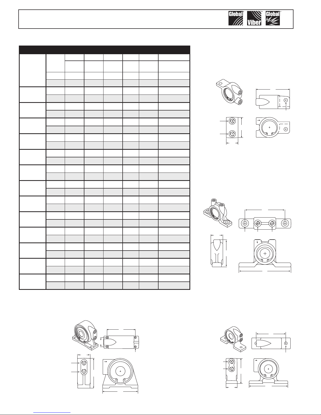
VII. Ball Vibrator Dimensions
Ball Vibrator Dimensions
A B C D E F
VIBRATOR
MODEL
BS-10
BS-16
BS-19
BS-25
US-13
US-19
US-25
US-38
CS-19
CS-25
CS-35
DS-41
DS-51
WEIGHT
0.70 1.90 3.10 1.10 1/8 0.34 Single Bolt
0.32 48 79 28 9
1.40 2.50 4.00 1.30 1/4 0.44 Single Bolt
0.64 64 102 33 11
1.90 2.80 4.50 1.50 1/4 0.44 Single Bolt
0.86 71 114 38 11
3.10 3.20 5.20 1.80 1/4 0.44 Single Bolt
1.41 81 132 46 11
1.20 2.70 5.20 1.20 1/8 0.34 4.00
0.54 69 132 30 9 102
2.20 3.40 5.10 1.50 1/4 0.44 4.00
1.00 86 130 38 11 102
3.50 3.90 6.60 1.80 1/4 0.44 5.00
1.59 99 168 46 11 127
7.60 5.40 7.90 2.30 3/8 0.56 6.00
3.45 137 201 58 14 152
2.40 3.40 5.30 1.50 1/4 0.44 4.00
1.09 86 135 38 11 102
4.30 4.40 5.40 2.10 1/4 0.53 4.00
1.95 112 137 53 13 102
4.60 4.40 5.40 2.10 1/4 0.53 4.00
2.09 112 137 53 13 102
10.40 5.70 6.80 2.50 1/2 0.41 5.50 X 1.80
4.72 145 173 64 10 140 X 45
10.80 5.70 6.80 2.50 1/2 0.41 5.50 X 1.80
4.90 145 173 64 10 140 X 45
HEIGHT LENGTH WIDTH INLET
lb in lb lb in in in
kg mm mm mm NPT mm mm
BOLT
HOLE
BOLT
CENTERS
A I R B L A STER SVIBRA T O R SVIBRA T O R S
BS Series - Have a single
bolt hole mounting base.
B
D
A
exhaust
C
US Series - Air travels in
a “U” pattern.
F
C
E
exhaust
D
A
CS Series - Air travels in a
“C” pattern.
E
DS Series - These models have a four bolt
mounting base.
F
C
D
exhaust
6
A
F
F
E
E
D
exhaust
B
A
C
B
 Loading...