

Page 1
1
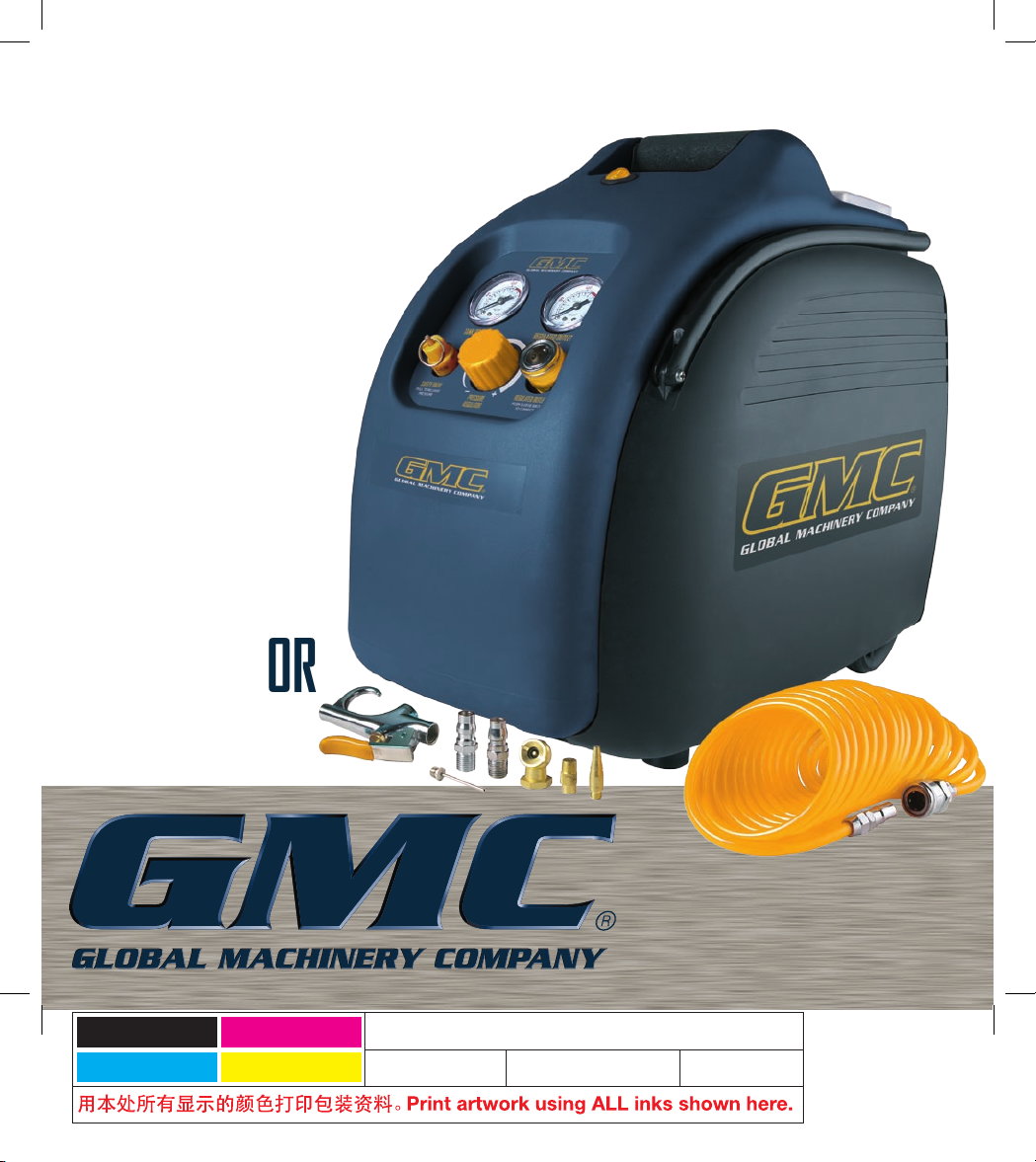
6LT
OIL-LESS
COMPRESSOR
MOC6L
INSTRUCTION MANUAL
Black
Cyan
Magenta
Yellow
Code: MOC6L IM
Date: 070620 Edition: 02 Op: MM
Page 2

2
Contents
Warranty Power Tools
Whilst every effort is made to ensure your complete
satisfaction with this tool, occasionally, due to the mass
manufacturing techniques, a tool may not live up to our
required level of performance and you may need the
assistance of our service department.
This product is warranted for a 2-year period for home
domestic use from the date of the original purchase.
If found to be defective in materials or workmanship,
the tool or the offending faulty component will be repaired
or replaced free of charge with another of the same item.
A
small freight charge may apply. Proof of purchase is
essential. We reserve the right to reject any claim where
the purchase cannot be verified.
This warranty does not include damage or defects to the
tool caused by or resulting from abuse, accidents,
alterations or commercial or business use. It also does not
cover any bonus items or included accessories. Only the
power tool is covered under this warranty.
With continuing product development, changes may have
occurred which render the product received slightly
different to that shown in this instruction manual.
Please ensure that you store your receipt in a safe place.
Conditions apply to the above warranty. For full details of
the warranty terms and conditions please refer to our
website – www.gmcompany.com
For prompt service we suggest you log your service
request online - www.gmcservice.com.au, should you
not have access to the internet, please contact our
service department on 1300 880 001 (Australia)
or 0800 445 721 (New Zealand).
Warranty 2
Warning labels explained 3
Introduction 4
Environmental protection 4
Description of symbols 4
Specifications 4
General safety rules 5-6
Additional safety rules for air compressors 6-7
Unpacking 8
Components 8
Know your product 9
To start the air compressor 10
Operating the air compressor 10
Stopping the air compressor 11
Assembly - Included Accessories 11
Operating the quick change blow gun 11
Connecting the inflation needle
to the quick change blow gun 12
Connecting the tapered hose fitting
to the quick change blow gun 12
Connecting the tyre inflator 13
Troubleshooting 13-16
Maintenance 16
General inspection 16
Cleaning 17
Power cord maintenance 17
Page 3
3
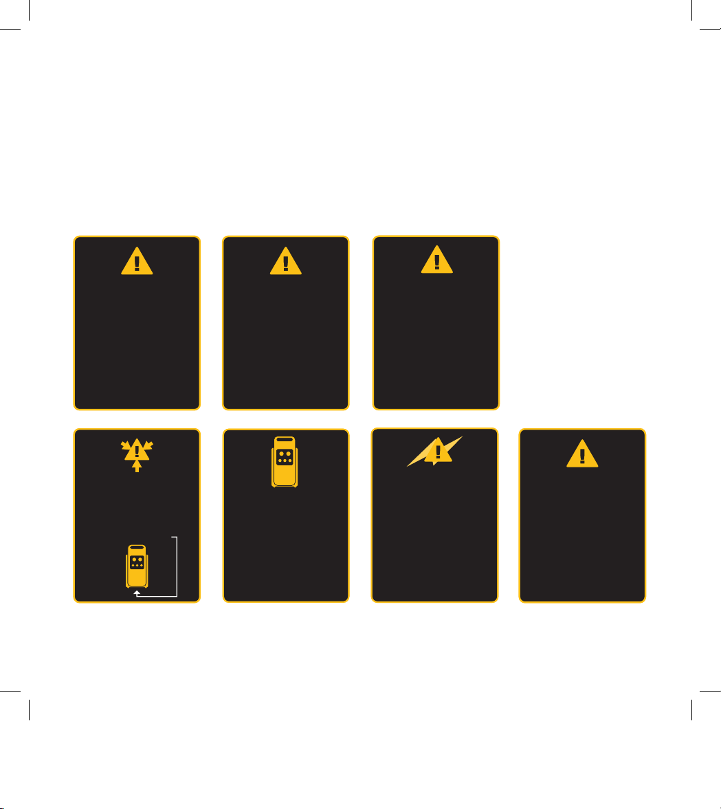
Warning labels explained
On the tank of your air compressor you will notice various
warnings about the operation of the compressor. These
warnings and the procedures associated with them are
explained fully in this manual on the following pages.
Please take note of these. They are important for your
safety and that of others in the vicinity.
Air discharged from
this unit is not
suitable for human
consumption.
Test the safety relief
valve daily.
Refer the instruction
manual.
To prevent build-up of
condensation, open
drain cock daily
Unit starts
automatically.
Switch off power
supply, remove
plug & relieve air
pressure prior to
commencing
service tasks.
Read instruction manual
prior to starting unit.
This equipment operates
from AC mains only.
Ensure mains outlet
is adequately rated for
this unit.
High voltage used on this
equipment. Prior to
servicing or removing the
cover, switch off the
power supply & remove
plug from mains.
MOC6L Air Compressor
Tank capacity:
6 litres
Pump displacement:
148 l/m
Free air delivery:
72 l/m
Max. working pressure:
0.8 MPa/115psi
Page 4
4
Description of symbols
The rating plate on your tool may show symbols.
These represent important information about the
product or instructions on its use.
Wear hearing protection.
Wear eye protection.
Wear breathing protection.
Conforms to relevant standards
for electromagnetic compatibility.
Specifications
Power: 1.5HP/1100W
Voltage: 230-240 Vac ~ 50Hz
No load speed: 3300 min-1
Discharge pressure: 0.8 MPa(115 psi)
Tank capacity: 6 litres
Air outlet: Nitto style quick coupler
Dimensions: 525 x 285 x 455mm
Net weight: 13 kg
Cut-in pressure (factory set): 0.6MPa (85psi)
Cut-out pressure (factory set): 0.8MPa (115psi)
Maximum output pressure: 0.8MPa (115psi)
Free air delivery: 72 l/min (2.5 CFM)
Pump displacement: 148 l/min (5.2 CFM)
Introduction
Your new GMC power tool will more than satisfy
your expectations. It has been manufactured under
stringent GMC Quality Standards to meet superior
performance criteria.
You will find your new tool easy and safe to operate,
and, with proper care, it will give you many years
of dependable service.
CAUTION. Carefully read through this entire Instruction
Manual before using your new GMC Power Tool. Take
special care to heed the Cautions and Warnings.
Your GMC power tool has many features that will make
your job faster and easier. Safety, performance, and
dependability have been given top priority in the
development of this tool, making it easy to maintain
and operate.
Environmental protection
Recycle unwanted materials instead
of disposing of them as waste. All tools,
hoses and packaging should be sorted,
taken to the local recycling centre and
disposed of in an environmentally safe way
.
Page 5

5
General safety rules
WARNING. To use this tool properly, you must observe
the safety regulations, the assembly instructions and the
operating instructions to be found in this Manual. All persons
who use and service the machine have to be acquainted
with this Manual and must be informed about its potential
hazards. Children and infirm people must not use this tool.
Children should be supervised at all times if they are in the
area in which the tool is being used. It is also imperative
that you observe the accident prevention regulations in
force in your area. The same applies for general rules of
occupational health and safety.
WARNING. When using power tools, basic safety
precautions should always be taken to reduce the risk of
fire, electric shock and personal injury. Also, please read
and heed the advice given in the additional important
safety instructions.
Save these instructions
1. Work area
a. Keep work area clean and well lit. Cluttered and dark
areas invite accidents.
b. Do not operate power tools in explosive
atmospheres, such as in the presence of flammable
liquids, gases or dust. Power tools create sparks which
may ignite the dust or fumes.
c. Keep children and bystanders away while operating a
power tool. Distractions can cause you to lose control.
2. Electrical safety
a. Power tool plugs must match the outlet. Never
modify the plug in any way. Do not use any adapter
plugs with earthed (grounded) power tools.
Unmodified plugs and matching outlets will reduce risk
of electric shock.
b. Avoid body contact with earthed or grounded
surfaces such as pipes, radiators, ranges and
refrigerators. There is an increased risk of electric shock
if your body is earthed or grounded.
c. Do not expose power tools to rain or wet conditions.
Water entering a power tool will increase the risk of
electric shock.
d. Do not abuse the cord. Never use the cord for
carrying, pulling or unplugging the power tool.
Keep cord away from heat, oil, sharp edges or moving
parts. Damaged or entangled cords increase the risk of
electric shock.
e. When operating a power tool outdoors, use an
extension cord suitable for outdoor use. Use of a cord
suitable for outdoor use reduces the risk of electric shock.
3. Personal safety
a. Stay alert, watch what you are doing and use
common sense when operating a power tool.
Do not use a power tool while you are tired or under
the influence of drugs, alcohol or medication. A moment
of inattention while operating power tools may result in
serious personal injury.
b. Use safety equipment. Always wear eye protection.
Safety equipment such as dust mask, non-skid
safety shoes, hard hat, or hearing protection used for
appropriate conditions will reduce personal injuries.
c. Avoid accidental starting. Ensure the switch is in the
off position before plugging in. Carrying power tools with
your finger on the switch or plugging in power tools that
have the switch on invites accidents.
d. Remove any adjusting key or wrench before
turning the power tool on. A wrench or a key left
attached to a rotating part of the power tool may result
in personal injury.
e. Do not overreach. Keep proper footing and balance at
all times. This enables better control of the power tool in
unexpected situations.
f. Dress properly. Do not wear loose clothing or
jewellery. Keep your hair, clothing and gloves away from
moving parts. Loose clothes, jewellery or long hair can be
caught in moving parts.
Page 6

6
g. If devices are provided for the connection of dust
extraction and collection facilities, ensure these are
connected and properly used. Use of these devices
can reduce dust related hazards.
4. Power tool use and care
a. Do not force the power tool. Use the correct power tool
for your application. The correct power tool will do the job
better and safer at the rate for which it was designed.
b. Do not use the power tool if the switch does not turn
it on and off. Any power tool that cannot be controlled
with the switch is dangerous and must be repaired.
c. Disconnect the plug from the power source before
making any adjustments, changing accessories, or
storing power tools. Such preventive safety measures
reduce the risk of starting the power tool accidentally.
d. Store idle power tools out of the reach of children
and do not allow persons unfamiliar with the power
tool or these instructions to operate the power tool.
Power tools are dangerous in the hands of untrained users.
e. Maintain power tools. Check for misalignment or
binding of moving parts, breakage of parts and
any other condition that may affect the power tools
operation. If damaged, have the power tool repaired
before use. Many accidents are caused by poorly
maintained power tools.
f. Keep cutting tools sharp and clean. Properly
maintained cutting tools with sharp cutting edges are less
likely to bind and are easier to control.
g. Use the power tool, accessories and tool bits etc.,
in accordance with these instructions and in the
manner intended for the particular type of power
tool, taking into account the working conditions and
the work to be performed. Use of the power tool for
operations different from those intended could result in a
hazardous situation.
5. Service
a. Have your power tool serviced by a qualified repair
person using only identical replacement parts. This
will ensure that the safety of the power tool is maintained.
Additional safety rules for air compressors
WARNING. Before connecting a tool to a power source
(mains switch power point receptacle, outlet, etc.) be sure
that the voltage supply is the same as that specified on the
nameplate of the tool. A power source with a voltage greater
than that specified for the tool can result in serious injury to
the user, as well as damage to the tool. If in doubt, do not
plug in the tool. Using a power source with a voltage less
than the nameplate rating is harmful to the motor.
Always remove the plug from the mains socket before
making any adjustments or maintenance.
• To reduce the risk of fire or explosion, never spray
flammable liquids in a confined area. It is normal for
the compressor motor and pressure switch to produce
sparks during use. If sparks come into contact with petrol
vapours or solvents, they may ignite the vapours and
cause a fire or explosion.
• Do not operate this compressor in the presence of
explosive gases, due to the risk of explosion. Check all
working conditions and surrounds before turning the
compressor on. Pay special attention when operating the
compressor in a boat, pit or in any location where there is
not a constant flow of fresh air.
• Always operate the compressor in a well ventilated area.
Do not smoke while spraying. Do not spray where sparks
or flames are present. Keep the compressor as far away
from the spray area as possible.
• The solvents trichloroethane and methylene chloride can
chemically react with the aluminium used in some paint
spray guns and form an explosion. If these solvents are
used, ensure that only stainless steel spray equipment is
connected. The compressor is not affected by the use of
these solvents.
Page 7

7
• Never directly inhale the compressed air produced
by a compressor and do not use it for charging
breathing tanks.
• Do not use welding equipment in close proximity to the
compressor. Do not weld anything to the air tank of the
compressor: this could dangerously weaken the tank and
will void the warranty.
• Do not use the compressor outdoors when it is raining
or on a wet surface; either situation could cause an
electric shock.
• Always shut off the compressor after use and before
servicing. Push the rocker on/off switch to the off position.
Turn the power supply switch off and remove the
electrical plug from the power supply.
• Check the maximum pressure rating of any tools or
accessories that you intend using with the compressor.
The output pressure of the air from the compressor must
be regulated so that it never exceeds the rated pressure
of the tool or accessory.
• To avoid the risk of burns and injury from moving parts,
do not operate the compressor with out the compressor
being fully intact or without the safety shield. Allow hot
parts to cool before handling or servicing.
• Be certain to read all the labels on the containers of paint
or other materials to be sprayed. Closely follow all safety
instructions. Use a respirator mask if there is a chance
that you might otherwise inhale the spray material.
Carefully check the effectiveness of any respirator mask
you intend using.
• Always wear safety goggles or glasses when using the
air compressor. Never point the nozzle of an accessory
towards any part of your body or towards another person.
• Do not attempt to adjust the pressure switch.
• Drain the moisture from the tank daily. It will help
prevent corrosion.
• Pull the ring on the safety valve daily to ensure that it is
operating properly and to clear any possible blockages.
• Keep the compressor at least 300mm from the nearest
wall to ensure adequate ventilation for cooling purposes.
• Before transporting the compressor make sure that
the pressurized air is bled from the tank and that the
compressor is firmly secured.
• Protect the air hose and cord set from damage. Inspect
for weak or worn spots regularly and replace if necessary.
• Always press the on/off switch down to switch off the
compressor before switching off the power or removing
the power plug.
Note. The compressor does not require oil and is
self lubricating.
• After using the compressor, switch off the on/off switch,
connect the power supply and ensure all the air pressure
in the tank and hose has been released.
• Do not attempt to remove any part of the machine whilst
it is under pressure.
• Use safety equipment including safety goggles or
shield, ear protection, breathing or respirator mask and
protective clothing.
Wear goggles
Wear earmuffs
Wear a breathing mask
• Never apply the outlet air of this compressor directly on to
any part of a person’s body. Do not attempt to block the
air outlet with your finger or any part of your body.
• The tool must be used only for its prescribed purpose.
Any use other than those mentioned in this Manual will
be considered a case of misuse. The user and not the
manufacturer shall be liable for any damage or injury
resulting from such cases of misuse.
• The manufacturer shall not be liable for any changes
made to the tool nor for any damage resulting from
such changes.
• Even when the tool is used as prescribed it is not
possible to eliminate all residual risk factors.
Page 8

8
The following hazards may arise in connection with the
tool’s construction and design:
• Damage to the lungs if an effective breathing mask is
not worn.
• Damage to hearing if effective earmuffs are not worn.
• Damage to the eyes if effective safety goggles or shield
are not worn.
WARNING. In the event that an air line is cut or broken,
the air line needs to be immediately disconnected from
the compressor at the quick release fitting. This will
automatically stop the air from free flowing. A broken air
line which is not supported is extremely dangerous and can
whip around very quickly, both with the capability of striking
people, and blowing foreign particles into the air.
Do not attempt to catch the air line but immediately keep
bystanders well clear. Disconnecting the remaining hose
from the quick release fitting on the unit will automatically
shut off the air supply. Turn off the compressor at the On /
Off rocker switch.
Unpacking
Due to modern mass production techniques, it is unlikely
that your GMC Power Tool is faulty or that a part is missing.
If you find anything wrong, do not operate the tool until the
parts have been replaced or the fault has been rectified.
Failure to do so could result in serious personal injury.
Components
The MOC6L air compressor is supplied with the
following components:
a. Air compressor
b. Blow gun
c. Blow gun adaptor
d. Tapered inflation fitting
e. Tire chuck
f. Inflation needle
g. Nitto fitted air hose coil
h. 1/4” male nitto plugs/adaptors (X2)
i. Roll of teflon tape
Page 9

9
Know your product
1. On/off switch
2. Handle
3. On board removable
storage container
4. Fold away handle
5. Cooling air outlets
6. Wheels (X2)
7. Levelling feet (X2)
8. Quick connect regulated
outlet valve
9. Regulating knob
10. Safety valve
11. Tank pressure gauge
12. Regulated outlet pressure gauge
13. Drain cock
14. Power cord storage
15. Blow gun
16. Blow gun adaptor
17. Tapered inflation fitting
18. Tire chuck
19. Inflation needle
20. Nitto fitted air hose coil
21. 1/4” Nitto male
plugs/adaptors (X2)
1
2
3
67
8
9
10
11
12
21
15
19
18
16
20
17
13
14
5
4
Page 10

10
To start the air compressor
1. Check the rating label on the compressor
indicates 230V-240V.
2. Make sure that the selected location for the compressor
is clean, dry, well ventilated and without any obstruction.
3. Conduct a visual check to the make sure that compressor
is not damaged and is fully in tack.
4. Make sure that he drain cock (13) is installed and
screwed into the closed position.
5. Connect the air hose to the quick coupler located on the
air compressor, by pushing back the outer sleeve of the
quick coupler (Fig. A) and inserting the end of the hose.
Release the outer sleeve and make sure the hose stays
in place (Fig. B).
6. Install the desired air accessory into the quick coupler at
the end of air hose by pulling back on the outer sleeve
of the quick coupler and inserting the accessory into it.
Release the outer sleeve and make sure the accessory
and hose are securely connected. For instructions on
how to assemble the accessories refer to pages 11 and 12.
7. Plug in the mains cable of
the compressor to a standard
240V household power point
and turn it on.
8. To start the compressor, press
the yellow “On/Off” (1) switch
to the “on” setting located on
top of the compressor (Fig. C).
WARNING. Be aware that pressurised air will be discharged
from the outlet and care should be taken that this discharge
is not directed towards you the operator, or other persons
within the area.
9. To stop the compressor, push the yellow “On/Off” (1)
switch to the “off” setting.
Operating the air compressor
1. The pressure in the tank is controlled by the action of
a pressure switch. When the set maximum pressure is
reached the pressure switch activates and the motor
is switched off. The pressure then decreases as the
air is used by the connected tool until the set minimum
pressure is reached after which the pressure switch
causes the motor to switch on again. The operator of
the compressor should be well aware that during use of
the compressor the motor will start and stop under the
influence of the rising or falling pressure in the tank. The
motor will start without any warning.
2. The maximum and minimum pressures are factory set
and the operator should not try to change them.
3. All accessories are connected
to the regulated outlet valve (8).
4. The pressure of the regulated
outlet, as shown on the
regulated outlet pressure
gauge (12), can be changed
by turning the regulating
knob (9) (Fig. D).
Note. To obtain the correct output reading on the regulated
output gauge, the air must be flowing through the regulated
outlet valve and the selected air tool/accessory.
The air pressure regulating knob should be adjusted
and the gauge must be read. Only read the gauge when
the regulated outlet valve has the air hose connected
with the selected air tool/accessory attached and drawing
air/discharging.
Do not start the application until you have set the regulated
outlet pressure accordingly for the selected tool/accessory.
A B
C
D
Page 11

11
To increase the regulated air pressure rotate the pressure
regulating knob clockwise. To decrease the regulated air
pressure rotate the regulating knob anti-clockwise.
When setting the the regulated outlet pressure always start
with the pressure being low, working your way up to the
desired regulated pressure.
Note. Ifyou do not allow the air to discharge while you
are setting the regulator, the pressure as indicated on the
regulated outlet gauge will be incorrect. This gauge ONLY
indicates the correct pressure while air is being discharged
from the outlet and through the air tool/accessory to be used.
Stopping the air
compressor
On completion of using the
compressor, or when you are
leaving the compressor unattended,
turn off the compressor in the
following way:
1. Switch the yellow “On/Off”
(1) switch to the “off” position
(Fig. E).
2. Switch off the electrical power
supply and remove the electrical
plug.
3. Set the regulated outlet pressure
to zero by turning the pressure
regulating knob (9) anti clockwise
and set the regulated outlet
pressure gauge (12) to zero
(Fig. F).
4. Disconnect the air hose,
accessories and air tool from
the compressor.
5. Pull the ring on the safety valve
(10) to ensure all the pressurised
air is released from the tank (Fig. G), or open the drain
cock (13) to release the pressure from the tank.
Note. Always shut off the compressor after use and
before servicing.
WARNINGS.
1. Never attempt to remove any part of the compressor
whilst the tank is under pressure.
2. Never attempt to remove any electrical component
whilst the compressor is connected to the power supply.
Switch off the power and remove the electrical plug.
3. Do not adjust the safety valve.
4. Take care when discharging air from the tank, i.e.
from the safety valve, the drain cock or the air outlet.
Compressed air can be extremely dangerous. Make
sure that the discharged air does not cause dust, stones
or any other foreign particles to be blown through the
air and that the air is discharged in a safe manner.
Assembly - Included Accessories
Your air compressor accessory kit comes with a variety
of accessories.
Operating the quick change blow gun
1. The air gun can be connected to the regulated air outlet
supply on the compressor.
2. Prior to connecting to the air
line, you need to assemble
the quick change blow gun.
To assemble select one of the
supplied 1/4” male Nitto style
plugs/adaptors (21). Apply the
supplied Teflon tape to the male
thread on the 1/4” male Nitto
style plug/adaptor (21) (Fig. H).
Screw the 1/4” male Nitto style
plug/adaptor (21) into the air
1/4” female threaded air inlet
side of the quick change blow
gun (15). Tighten this fitting
with a wrench for an air tight
seal (Fig. I).
E
F
G
H
I
Page 12

12
3. Connect the completed assembly to the air line by
pulling back the outer sleeve of the quick coupler at the
end of the air hose and insert the quick change blower
assembly. Once inserted, release the outer sleeve of
the coupling and make sure the accessory and hose are
securely connected.
For instructions on how to assemble the accessories to
the outlet side of the quick release blow gun refer to
page 12 of this manual.
4. To discharge the air from
the gun, squeeze the trigger
(Fig. J). The further the
trigger is squeezed, the
greater the discharge.
5. To stop the air discharging,
release the trigger.
Note. When connecting accessories to the outlet of the quick
change blow gun (15) always disconnect it from the hose
first. This will allow you more freedom as well as provide
for a more easier and safer attachment/detachment of
accessories. The dust blow gun is to be used in conjunction
with either the tapered inflation fitting (17) or the inflation
needle (19).
IMPORTANT. Take extreme care when using the blow gun
air tool. The discharge air velocity is VERY high.
• Never point the air gun at anyone.
• Think when you are using the gun. Never allow
debris to be blown in the direction of another person,
or other objects.
• Use safety glasses, a face or dust mask and appropriate
clothing for the task being undertaken.
• Never apply the outlet of the air gun against a
person’s body.
• Never look down the air outlet hole of the gun.
Connecting the inflation needle
to the quick change blow gun
In order to use the inflation needle you are required to
attach the blow gun adaptor (16) to the blow gun (15).
Proceed to screw in the inflation needle (19) to the safety
nozzle (Fig. K&L).
IMPORTANT. Take extreme care when using the
inflation needle.
• Never point the needle at anyone.
• Use safety glasses, a face or dust mask and appropriate
clothing for the task being undertaken.
• Never apply the outlet of the needle against a
person’s body.
• Never look down the air outlet hole of the inflation needle
• Always apply lubricant to the needle before inserting
and inflating.
• When inserting the needle, insert the open end of the
needle into the valve in a slow and safe manner.
Connecting the tapered inflation fitting to the
quick change blow gun
In order to use the tapered
inflation fitting you are required to
attach the blow gun adapter (16)
to the blow gun (15). Proceed
to screw in the tapered inflation
fitting (17) to the blow gun
adaptor (16) (Fig. M).
J
L
K
M
Page 13

13
Connecting the tyre inflator
1. To connect the tyre inflator,
select one of the supplied 1/4”
male Nitto style plugs/adaptors
(21). Apply the supplied Teflon
tape to the male thread on
the 1/4” male Nitto style plug/
adaptor (21). Screw the 1/4”
male Nitto style plug/adaptor
(21) into the 1/4” female thread
of the tyre inflator (18). Tighten this fitting with a wrench for
an air tight seal (Fig. N).
2. Connect the completed assembled tyre inflator to the air
line by pulling back the outer sleeve of the quick coupler
at the end of the air hose and insert the tyre inflator
assembly. Once inserted, release the outer sleeve of
the coupling and make sure the accessory and hose are
securely connected.
3. To operate the tyre inflator insert the tyre valve inlet
connection into the tyre inflator.
4. Firmly press the tyre inflator down; doing so opens
both the valve on the tyre and the valve on in the tyre
inflator allowing air to flow through. Use a tyre gauge to
check air pressure in the tyres. Check the ratings printed
on the side walls of the tyre that you are inflating for
reference as to the recommended maximum air pressure
requirement. DO NOT EXCEED the maximum pressure
ratings on the tyre you are inflating.
IMPORTANT.
• The tyre inflator should only be used for its intended
purpose to inflate tyres.
• Do not discharge air through the inflator without it being
fitted to a tyre.
• Never apply the outlet of the tyre inflator against a
person’s body.
• Never look down the air outlet hole of the inflator.
• Never point the tyre inflator at anyone.
• Do not over inflate the tyres beyond the recommended air
pressure from the tyre manufacturer.
N
Troubleshooting
Problem Possible cause Possible remedy
Motor will not run, running too
slow or becoming excessively hot
Power fault or supply voltage too low Check the power supply
Faulty pressure switch Use authorised service centre
to repair or replace the switch
Faulty motor Use authorised service centre
to repair or replace the motor
Main compressor sticking/tight Use authorised service centre
to repair or replace faulty parts
Main compressor sticking/tight
Moving parts damaged by heat Use authorised service centre to
check crankshaft, bearings, con rod,
piston rings, etc and replace
where necessary
Moving parts damaged or blocked
by foreign particle
Page 14

14
Troubleshooting continued
Problem Possible cause Suggested remedy
Vibration or abnormal noise
Loose part Use authorised service centre
to check and repair if necessary
Foreign body in main compressor Use authorised service centre
to check and clean if necessary
Piston connecting with the valve seat Use authorised service centre
to increase size of gasket
Moving parts excessively worn Use authorised service centre
to repair or replace
Insufficient pressure or decreased
outlet capacity
Motor running too slow Use authorised service centre to check
and repair if necessary
Leaking safety valve Use authorised service centre to repair
or replace the switch
Leaking pipe Use authorised service centre to check
and repair if necessary
Damaged gasket Use authorised service centre to check
and repair if necessary
Damaged or carbon coated valve seat Use authorised service centre to check
and repair if necessary
Damaged piston ring or cylinder Use authorised service centre to check
and repair if necessary
Incorrectly adjusted regulator Adjust and set the regulator correctly.
Page 15

15
Troubleshooting continued
Problem Possible cause Suggested remedy
Insufficient pressure or decreased
outlet capacity continued
The tool requires air supply outside the
range of the compressors capabilities.
1) Select another air tool that that will
allow you to achieve the same end
result which will operate within the
compressors capabilities.
2) Select another tool to achieve the
same result (could be a power tool
or hand tool) to perform the task.
3) Purchase a suitable air
compressor from the GMC range
that will run the required tool.
Drain cock may not be fully closed. Check the drain cock to ensure it has
been fully closed. If not tighten.
Safety valve fully leaking. Check out the condition of the
safety valve. If the valve is leaking
immediately shut off the compressor
and cease using. Have the unit
serviced/checked by an authorised
service centre and repaired. Don’t
continue to use the unit with a leaking
safety valve.
Air line hose leaking Examine the air hose for any holes
and tears. If you find any holes or tears
replace the air hose.
Page 16

16
Troubleshooting continued
Problem Possible cause Suggested remedy
Insufficient pressure or decreased
outlet capacity continued
Air fittings leaking. Check all air fittings. Make sure that
they are tight and not leaking at the
joins. If a quick release fitting is leaking,
disconnect it and reconnect it. If it
continues to leak replace the defective
fitting(s). If a male or female fitting
is leaking around the thread tighten
using a spanner. If the fitting is already
tight and can’t be tightened anymore
unscrew the connection, remove the
Teflon tape and look at the condition
of the fitting(s). If the a fitting(s) is
damaged replace and reassemble
using Teflon tape on threaded fittings.
If the fitting looks OK or reapply Teflon
tape and re assemble.
Maintenance
1. After each day of operation,
use the drain cock (13) under
the tank to drain out any
condensation (Fig. O).
2. After each day of operation
check daily the operation of
the safety valve (10). This
check should be performed
when the tank contains close
to max pressure.
To check the valve, pressurise the tank, and pull the
ring OUTWARDS on the safety valve.
Air should discharge from the valve.
Release the ring of the safety valve. When the ring is
released the air discharge must stop.
WARNINGS.
Safety glasses must be worn when performing this test.
Do not have your face close to the safety valve when
performing this test as air will discharge from the valve at a
high force.
If the safety valve does not operate correctly in any way as
described above, turn off the compressor immediately and
have the compressor and safety valve checked and tested
at an authorised Service centre.
DO NOT CONTINUE TO USE THE COMPRESSOR IN
ANY WAY IF THE SAFETY VALVE DOES NOT WORK
AS ABOVE.
General inspection
1. Regularly check that all the fixing screws are tight.
2. The supply cord of the tool should be checked frequently
for damage. If damaged, have the cordset replaced by an
authorised service facility to avoid a hazard.
O
Page 17

17
Cleaning
1. Keep the tool’s air vents unclogged and clean at all times.
2. Remove dust and dirt regularly. Cleaning is best done
with a soft brush or a rag.
3. Re-lubricate all moving parts at regular intervals.
4. If the body of the compressor needs cleaning, wipe it
with a soft damp cloth. A mild detergent can be used but
nothing like alcohol, petrol or other cleaning agent.
5. Never use caustic agents to clean plastic parts.
CAUTION. Water must never come into contact with
the tool.
Power cord maintenance
Only an authorised service centre should replace the
cordset or carry out other repairs. If the cordset is damaged
or worn, have it repaired or replaced by an authorised
service centre.
Page 18

18
Page 19

19
Page 20

GMC customer assist
If your product needs repairing, replacing,
technical service or you simply need help or advice,
please contact us on our Customer Assist Line
1300 880 001 (Australia) or 0800 445 721 (New Zealand).
For prompt service we suggest you log your service request
online at www.gmcservice.com.au. Should you not have
access to the Internet, please contact our service department
on 1300 880 001 (Australia) or 0800 445 721 (New Zealand).
7am –7pm, 7days a week (AEST).
Please note that if repair or replacement is required,
you must provide a valid original purchase receipt.
You will need the following details at hand to log your service request;
Personal details: First & Last name, address, pick up address,
contact phone numbers, email address
Product details: Product number, date of purchase, retailer bought from,
State & postcode, receipt number,
reason for the request,
c
opy of official purchase receipt
Attach your purchase receipt and save with this Manual for future reference
.
Please refer to our website www.gmcompany.com for full GMC warranty Terms and Conditions.
 Loading...