

Page 1
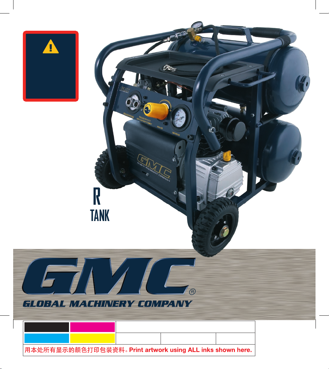
1
2HP/1600W
32LT
DUAL TANK
COMPRESSOR
WITH REMOVABLE TANK
DTC32L
INSTRUCTION MANUAL
Black
Cyan
Magenta
Yellow
Code: DTC32L IM
Date: 070705 Edition: 05 Op: GM
When filter becomes
dirty or oily, clean or
replace filter. Refer to
instruction manual.
Do not switch on
for the first time
without first
filling with oil.
To prevent build-up of
condensation, open
drain cock daily
Read instruction manual
prior to starting unit.
This equipment
operates from
AC mains only.
Unit starts
automatically.
Switch off power supply,
remove plug & relieve
air pressure prior to
commencing service
tasks.
DTC32L Air Compressor
Tank capacity:
32 litres
Pump displacement:
206 l/m
Free air delivery:
114 l/m
Max. working pressure:
0.8 MPa
Check the oil level before starting the
compressor every time.
Make sure the compressor is on a level
surface prior to checking the oil level.
The oil level is required to be at the
red dot on the oil level sight glass
prior to use.
Use only oil grade specified in the
instruction manual.
Page 2

2
Contents
Warranty Power Tools
Whilst every effort is made to ensure your complete
satisfaction with this tool, occasionally, due to the mass
manufacturing techniques, a tool may not live up to our
required level of performance and you may need the
assistance of our service department.
This product is warranted for a 2-year period for home
domestic use from the date of the original purchase.
If found to be defective in materials or workmanship,
the tool or the offending faulty component will be repaired
or replaced free of charge with another of the same item.
A
small freight charge may apply. Proof of purchase is
essential. We reserve the right to reject any claim where
the purchase cannot be verified.
This warranty does not include damage or defects to the
tool caused by or resulting from abuse, accidents,
alterations or commercial or business use. It also does not
cover any bonus items or included accessories. Only the
power tool is covered under this warranty.
With continuing product development, changes may have
occurred which render the product received slightly
different to that shown in this instruction manual.
Please ensure that you store your receipt in a safe place.
Conditions apply to the above warranty. For full details of
the warranty terms and conditions please refer to our
website – www.gmcompany.com
For prompt service we suggest you log your service
request online - www.gmcservice.com.au, should you
not have access to the internet, please contact our
service department on 1300 880 001 (Australia)
or 0800 445 721 (New Zealand).
Warranty 2
Warning labels explained 3
Introduction 4
Environmental protection 4
Description of symbols 4
Specifications 4
General safety instructions 5
Additional safety rules for air compressors 6
Contents of carton 8
Know your product 8
Unpacking 10
Assembly 10
Pre-start routine 10
To start & stop the compressor 11
Operation 11
Tank removal/installation 12
Troubleshooting 14
Maintenance 16
General inspection 16
Cleaning 16
Power cord maintenance 16
Page 3
3
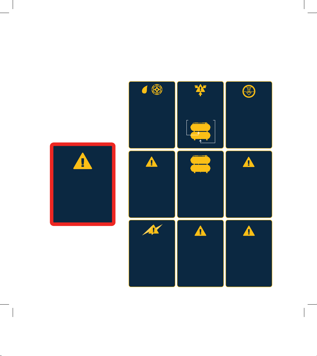
Warning labels explained
On the tank of your air compressor you will notice various
warnings about the operation of the compressor. These
warnings and the procedures associated with them are
explained fully in this manual on the following pages.
Please take note of these. They are important for your
safety and that of others in the vicinity.
Air discharged from
this unit is not
suitable for human
consumption.
Test the safety relief
valves daily.
Refer the instruction
manual.
When filter becomes
dirty or oily, clean or
replace filter. Refer to
instruction manual.
Do not switch on
for the first time
without first
filling with oil.
To prevent build-up of
condensation, open
drain cock daily
Read instruction manual
prior to starting unit.
This equipment
operates from
AC mains only.
High voltage used on
this equipment. Prior to
servicing or removing the
cover, switch off the
power supply & remove
plug from mains. Ensure
mains outlet is adequately
rated for this unit.
Unit starts
automatically.
Switch off power supply,
remove plug & relieve
air pressure prior to
commencing service
tasks.
DTC32L Air Compressor
Tank capacity:
32 litres
Pump displacement:
206 l/m
Free air delivery:
114 l/m
Max. working pressure:
0.8 MPa
Check the oil level before starting the
compressor every time.
Make sure the compressor is on a level
surface prior to checking the oil level.
The oil level is required to be at the
red dot on the oil level sight glass
prior to use.
Use only oil grade specified in the
instruction manual.
Page 4
4
Description of symbols
The rating plate on your tool may show symbols.
These represent important information about the
product or instructions on its use.
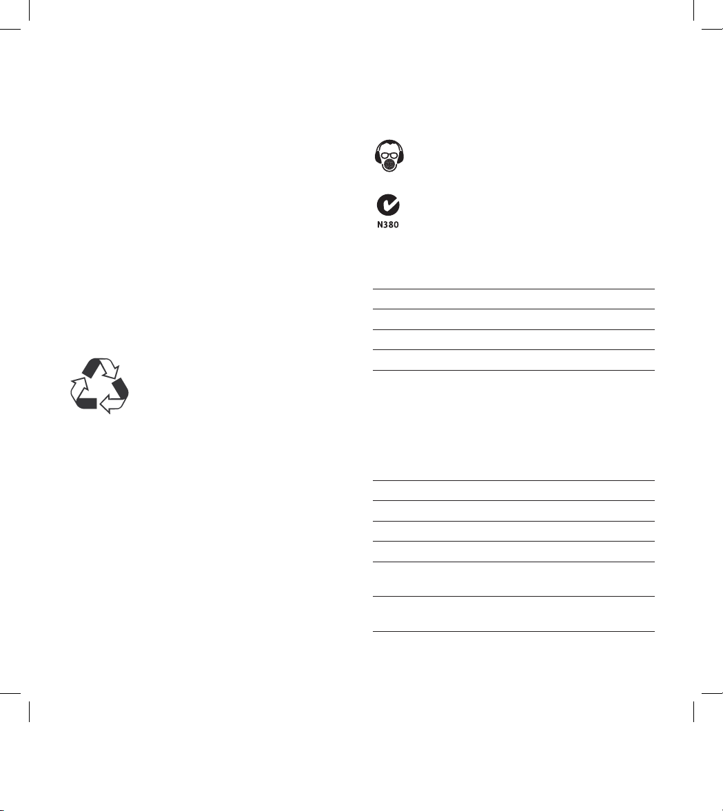
Wear hearing protection.
Wear eye protection.
Wear breathing protection.
Conforms to relevant standards
for electromagnetic compatibility.
Specifications
Power: 2HP/1600W
Voltage: 230–240V ~ 50Hz
No load speed: 2850 min
-1
Discharge pressure: 0.8 MPa(115 psi)
Tank capacity: 32/16 litres
Air outlets X4:
- 2X regulated fitted with Nitto style quick
release couplings
- 1X fitted Nitto style quick release coupler
- 1X fitted tyre inflation hose & gauge
providing easy tyre inflation applications.
Net weight: 38.5kgs
Cut-in pressure (factory set): 0.6MPa (85psi)
Cut-out pressure (factory set): 0.8MPa (115psi)
Maximum output pressure: 0.8MPa (115psi)
Free air delivery: 114 l/min
(4 CFM)
Pump displacement: 206 l/min
(7.3 CFM)
Introduction
Your new GMC power tool will more than satisfy
your expectations. It has been manufactured under
stringent GMC Quality Standards to meet superior
performance criteria.
You will find your new tool easy and safe to operate,
and, with proper care, it will give you many years
of dependable service.
CAUTION. Carefully read through this entire Instruction
Manual before using your new GMC Power Tool. Take
special care to heed the Cautions and Warnings.
Your GMC power tool has many features that will make
your job faster and easier. Safety, performance, and
dependability have been given top priority in the
development of this tool, making it easy to maintain
and operate.
Environmental protection
Recycle unwanted materials instead
of disposing of them as waste. All tools,
hoses and packaging should be sorted,
taken to the local recycling centre and
disposed of in an environmentally safe way
.
Page 5

5
General safety instructions
To use this tool properly, you must observe the safety
regulations, the assembly instructions and the operating
instructions to be found in this Manual. All persons who use
and service the machine have to be acquainted with this
Manual and must be informed about its potential hazards.
Children and infirm people must not use this tool. Children
should be supervised at all times if they are in the area in
which the tool is being used. It is also imperative that you
observe the accident prevention regulations in force in your
area. The same applies for general rules of occupational
health and safety.
WARNING. When using power tools, basic safety precautions
should always be taken to reduce the risk of fire, electric
shock and personal injury. Also, please read and heed the
advice given in the additional important safety instructions.
1. Keep the work area clean and tidy. Cluttered work areas
and benches invite accidents and injury.
2. Consider the environment in which you are working.
Do not use power tools in damp or wet locations. Keep
the work area well lit. Do not expose power tools to rain.
Do not use power tools in the presence of flammable
liquids or gases.
3. Keep visitors away from the work area. All visitors and
onlookers, especially children and infirm persons, should
be kept well away from where you are working. Do not
let others in the vicinity make contact with the tool or
extension cord.
4. Store tools safely. When not in use, tools should be
locked up out of reach.
5. Do not force the tool. The tool will do the job better and
safer working at the rate for which it was designed.
6. Use the correct tool for the job. Do not force small tools
or attachments to do the job best handled by a heavier
duty tool. Never use a tool for a purpose for which it was
not intended.
7. Dress correctly. Do not wear loose clothing or
jewellery. They can be caught in moving parts. Rubber
gloves and non-slip footwear are recommended when
working outdoors. If you have long hair, wear a protective
hair covering.
8. Use safety accessories. Safety glasses and earmuffs
should always be worn. A face or dust mask is also
required if the sanding operation creates dust.
9. Do not abuse the power cord. Never pull the cord to
disconnect the tool from the power point. Keep the cord
away from heat, oil and sharp edges.
10. Secure the work piece. Use clamps or a vice to hold the
work piece. It is safer than using your hand and frees
both hands to operate the tool.
11. Do not overreach. Keep your footing secure and
balanced at all times.
12. Look after your tools. Keep tools sharp and clean for
better and safer performance. Follow the instructions
regarding lubrication and accessory changes. Inspect
tool cords periodically and, if damaged, have them
repaired by an authorised service facility. Inspect
extension cords periodically and replace them if
damaged. Keep tool handles dry, clean and free from oil
and grease.
13. Disconnect idle tools. Switch off the power and
disconnect the plug from the power point before
servicing, when changing accessories and when the tool
is not in use.
14. Remove adjusting keys and wrenches. Check to see
that keys and adjusting wrenches are removed from the
tool before switching on.
15. Avoid unintentional starting. Always check that the
switch is in the OFF position before plugging in the tool
to the power supply. Do not carry a plugged in tool with
your finger on the switch.
16. Use outdoor rated extension cords. When a tool is used
outdoors, use only extension cords that are intended for
outdoor use and are so marked.
17. Stay alert. Watch what you are doing. Use common
sense. Do not operate a power tool when you are tired.
Page 6

6
18. Check for damaged parts. Before using a tool, check
that there are no damaged parts. If a part is slightly
damaged, carefully determine if it will operate properly
and perform its intended function. Check for alignment of
moving parts, binding of moving parts, breakage of parts,
proper mounting and any other conditions that may
affect the operation of the tool. A part that is damaged
should be properly repaired or replaced by an authorised
service facility, unless otherwise indicated in this
Instruction Manual. Defective switches must be replaced
by an authorised service facility. Do not use a tool if the
switch does not turn the tool on and off correctly.
19. Guard against electric shock. Prevent body contact
with grounded objects such as water pipes, radiators,
cookers and refrigerator enclosures.
20. Use only approved parts. When servicing, use only
identical replacement parts. Use an authorised service
facility to fit replacement parts.
Additional safety rules for air compressors
WARNING. Before connecting a tool to a power source
(mains switch power point receptacle, outlet, etc.) be sure
that the voltage supply is the same as that specified on the
nameplate of the tool. A power source with a voltage greater
than that specified for the tool can result in serious injury to
the user, as well as damage to the tool. If in doubt, do not
plug in the tool. Using a power source with a voltage less
than the nameplate rating is harmful to the motor.
Always remove the plug from the mains socket before
making any adjustments or maintenance, including
renewing the lubricating oil.
• To reduce the risk of fire or explosion, never spray
flammable liquids in a confined area. It is normal for
the compressor motor and pressure switch to produce
sparks during use. If sparks come into contact with petrol
vapours or solvents, they may ignite the vapours and
cause a fire or explosion.
• Always operate the compressor in a well ventilated area.
Do not smoke while spraying. Do not spray where sparks
or flames are present. Keep the compressor as far away
from the spray area as possible.
• The solvents trichloroethane and methylene chloride can
chemically react with the aluminium used in some paint
spray guns and form an explosion. If these solvents are
used, ensure that only stainless steel spray equipment is
connected. The compressor is not affected by the use of
these solvents.
• Never directly inhale the compressed air produced by a
compressor and do not use it for charging breathing tanks.
• Do not use welding equipment in close proximity to the
compressor. Do not weld anything to the air tanks of the
compressor: this could dangerously weaken the tanks
and will void the warranty.
• Do not use the compressor outdoors when it is raining
or on a wet surface; either situation could cause an
electric shock.
• Always shut off the compressor after use and before
servicing. Set the on/off switch to the off position, wait
for the pressurised air to bleed from both tanks via the
release valves located on each tank. Then remove the
electrical plug from the power supply.
• Check the maximum pressure rating of any tools or
accessories that you intend using with the compressor.
The output pressure of the air from the compressor must
be regulated so that it never exceeds the rated pressure
of the tool or accessory.
• To avoid the risk of burns and injury from moving
parts, do not operate the compressor with the safety
cover removed. Allow hot parts to cool before handling
or servicing.
• Be certain to read all the labels on the containers of paint
or other materials to be sprayed. Closely follow all safety
instructions. Use a respirator mask if there is a chance
that you might otherwise inhale the spray material.
Carefully check the effectiveness of any respirator mask
you intend using.
• Always wear safety goggles or glasses when using the
air compressor. Never point the nozzle of an accessory
towards any part of your body or towards another person.
• Do not attempt to adjust the pressure switch or the
release valve.
Page 7

7
• Drain the moisture from the tanks daily. It will help
prevent corrosion.
• Pull the ring on the safety valves daily to ensure that it
operating properly and to clear any possible instructions.
Note. This unit has two safety release valves (one on each
tank). Ensure both are checked daily.
• Keep the compressor at least 300mm from the nearest
wall to ensure adequate ventilation for cooling purposes.
• Prior to transporting the compressor make sure that the
pressurised air is bled from both tanks. Ensure that the
removable tank is correctly connected. Also check that
the compressor is firmly secured.
Note. Never transport pressurised tanks. Even when
transporting the removable air supply it must be empty
of all air.
• Protect the air hoses and cordset from damage. Inspect
for weak or worn spots regularly and replace if necessary.
• Prior to using the removable tank as a temporary air
supply make sure that you place it down on a level
surface and have a firm grip on the air hose prior to use.
• Do not use an extension cord with this product. Use
additional air hose instead of an extension cord to
prevent power loss and possible damage to the motor.
Use of an extension cord voids the warranty.
• After long working periods external metal parts could
be hot.
• Always shut off the compressor at the on/off switch by
lifting the lever to the off position before switching off the
power or removing the power plug.
• Check the oil level before starting the compressor
every time.
• Make sure the compressor is on a level surface prior to
checking the oil level.
• The oil level is required to be at the red dot on the oil
level sight glass prior to use.
• Use only oil grade specified in this instruction manual.
Note. The compressor is supplied empty of oil. It must be
filled with oil before first use.
• After using the compressor, switch off the on/off switch,
disconnect the power supply and open the outlet valves
on both tanks to release the pressure.
• Ensure that the lubricating oil is clean and that the oil
level is maintained at the correct level. Replace the oil
as indicated in the Maintenance section of this Manual.
• Use safety equipment including safety goggles or
shield, ear protection, breathing or respirator mask
and protective clothing.
Wear goggles
Wear earmuffs
Wear a breathing mask
Never apply air from any of the air outlets from this
compressor directly on to any part of a person’s body.
Do not attempt to block any of the air outlets with your
finger or any part of your body.
The tool must be used only for its prescribed purpose.
Any use other than those mentioned in this Manual will
be considered a case of misuse. The user and not the
manufacturer shall be liable for any damage or injury
resulting from such cases of misuse.
The manufacturer shall not be liable for any changes made
to the tool nor for any damage resulting from such changes.
Even when the tool is used as prescribed it is not possible to
eliminate all residual risk factors. The following hazards may
arise in connection with the tool’s construction and design:
• Damage to the lungs if an effective breathing mask is
not worn.
• Damage to hearing if effective earmuffs are not worn.
• Damage to the eyes if effective safety goggles or shield
are not worn.
Page 8

8
WARNING. In the event that an air line is cut or broken,
the air line needs to be immediately disconnected from
the compressor at the quick release fitting. This will
automatically stop the air from free flowing. A broken air
line which is not supported is extremely dangerous and can
whip around very quickly, both with the capability of striking
people, and blowing foreign particles into the air.
Do not attempt to catch the air line but immediately keep
bystanders well clear. Disconnecting the remaining hose
from the quick release fitting on the unit will automatically
shut off the air supply. Turn off the compressor at the
On / Off switch.
Contents of carton
• 400ml of oil in a sealed container
• Instruction manual
Page 9

9
Know your product
1. Handle
2. On/off switch
3. Tank pressure gauge x 2
4. Regulated Nitto style
quick release air outlets x 2
5. Regulating knob
6. Regulated outlet pressure gauge
7. Safety valve x 2
8. Combination valve
(Non return, outlet and
safety release in one valve)
9. Drain cock x 2
10. Air tank 1 (Removable tank)
11. Air tank 2
12. Wheels (x 2)
13. Safety cover
14. Oil filling plug
15. Air filter
16. Oil sight glass/Oil drain plug
17. Power Cord
18. Tank 1 air isolation valve
19. Console/Tray
20. Tank 1 (removable tank) handle
21. Vibration dampening feet
22. Tank 1 rubber support straps
23. Tank 1 support brackets
24. Tank 1 feet (located at each end of the tank)
25. Tank 1 air inlet hose
26. Tank 1 Nitto style quick
release air inlet valve
27. Tank 1 inflator hose
19
2
6
11
4
5
3
8
10
12
13
14
15
1617 18
1
20
23
25
26
27
22
24
7
9
21
16
3
7
Page 10

10
Unpacking
Due to modern mass production techniques, it is unlikely
that your GMC Power Tool is faulty or that a part is missing.
If you find anything wrong, do not operate the tool until the
parts have been replaced or the fault has been rectified.
Failure to do so could result in serious personal injury.
Assembly
Oil
WARNING. The air compressor must be filled with oil
before first use.
To prevent possible spillage of oil during transport, the
compressor oil is supplied in a separate container. It must
be added to the compressor before turning the compressor
on. Failure to add the oil will cause non-repairable damage
to the compressor and will void the warranty.
1. Remove the plastic oil filling plug (14) located on the top
of the crank case of the compressor housing.
2. Use the oil supplied to fill the crank case until the oil level
as seen in the oil sight glass (16) is up to the mid point of
the red circle.
3. Replace the oil filling plug (14). Ensure the plug is fully
fitted and firmly in position.
Pre-start routine
1. Ensure that the location for the compressor is clean,
dry and well ventilated.
2. Ensure the crank case has been filled with oil and is
at the correct level.
3. Start the compressor by
following the procedure in the
section “To start and stop
the compressor”. Prior to
the first time operation of the
compressor open the drain
cocks in both of the tanks (9),
run the compressor for
20 - 30 minutes in this condition
with no load and to ensure all
parts are well lubricated.
4. Turn the air compressor off at
the on/off switch (2) on the air
compressor. Close the drain
cocks (9) in both tanks.
Your compressor is now ready
for use.
WARNING. Be aware that pressurised air will be discharged
from the drain cocks (9) and care should be taken that this
discharge is not directed towards you the operator, or other
persons within the area.
To start & stop the compressor
1. Check the rating label on the compressor indicates
230V–240V.
2. Plug in the mains cable of
the compressor to a standard
240V household power point
and turn on.
3. To start the compressor, push
the On/Off lever (2) downward
so that the lever is in the
vertical position.
4. To stop the compressor, lift the
On/Off lever (2) to the horizontal position.
OFF
ON
Page 11

11
Operation
1. The pressure in the tank is controlled by the action of
the pressure switch. When the set maximum pressure
is reached the pressure switch activates and the motor
is switched off. The pressure then decreases as the
air is used by the connected tool until the set minimum
pressure is reached after which the pressure switch
causes the motor to switch on again. The operator of
the compressor should be well aware that during use of
the compressor the motor will start and stop under the
influence of the rising or falling pressure in the tank. The
motor will start without any warning.
2. The maximum and minimum pressures are factory set
and the operator should not try to change them.
3. All accessories are connected to either the Nitto style
quick coupler regulated air
outlets (4) or the removable
tank inflator hose (27).
4. The pressure of the regulated
quick connect outlets is shown
on the regulated outlet pressure
gauge (6). The regulated
pressure can be adjusted by
turning the regulating knob (5).
Note. To obtain the correct output reading on the regulated
output gauge, the air must be flowing through the outlet(s)
(4). The regulating valve should be adjusted and the gauge
read with the outlet valve open and the air being discharged
from the regulated outlet through the accessory being
used. If you are using both of the regulated outlets (4)
simultaneously make sure that the tools being connected
have the same pressure operation requirements. To
increase the air pressure, rotate the regulating valve
clockwise. To decrease the pressure, rotate the regulating
valve anti-clockwise.
Note. If you do not allow the air to discharge while you
are setting the regulator, the pressure as indicated on the
regulated outlet gauge will be incorrect. This gauge ONLY
indicates the correct pressure while air is being discharged
from the outlet.
5. On completion of the task, i.e. when you have finished
using the compressor, or when you are leaving the
compressor unattended, turn off the compressor in the
following way:
• Lift the on/off switch (2) to the off position
• Wait for the pressurised air to bleed from the release valve.
Note. You will hear a short air discharge of approx
½ second however, this discharge only occurs if the
compressor is actually running at the time, and not in idle.
• Switch off the electrical
power supply and remove the
electrical plug.
• Pull the ring on both of the
safety valves (7) to ensure all
the pressurised air is released
from the tank, or open the both
drain cocks (9) to release the
pressure from the tank.
Tank removal/installation
This twin tank air compressor has the added benefit of a
removable tank which provides a mobile source of limited/
short term compressed air. This has many advantages
including inflating flat tyres on site as well as performing
small brad nailing tasks.
Note. It is important that end users understand the
capabilities of the removable tank and work with in it’s
capabilities.
Removing the air tank:
1. Turn the On/Off switch (2) on the compressor to the
off position.
2. Turn the power supply off and disconnect the power cable.
3. Lift the main handle (1) up and away from the portable tank.
Page 12

12
4. Close the tank 1 isolation valve (18).
5. Disconnect the tank 1 inlet hose (25) from the combination
valve (8), by sliding back the sleeve of the quick connect
fitting and removing the inlet hose.
Note. The inlet hose has been fitted with a special one way
valve. On removal of the inlet hose there will be a slight
discharge of air.
6. Place the tank 1 inlet hose
(25) on the provided clip.
7. Disconnect the rubber support
straps (22) by pulling them
over the support brackets (23)
to release the air tank.
WARNING. Be careful when
releasing the straps they do have
a tight fit.
8. The tank has now been
correctly disconnected from the
air compressor unit. You can
now move the tank freely
by using the carry handle (20)
to lift and move the tank. You
can now use the removed tank.
The separated tank has two
outlets that you can choose
from;
a) the attached inflation hose; or
b) the provided quick connect coupler that you can connect
another air hose to. This can be done by sliding back
the sleeve of the quick connect coupler and inserting an
air hose assembly that is fitted with a Nikko style fittings.
Due to the limited supply of air it is recommended that
the removable tank is fully charged with air prior to being
removed.
Note. While the tank has been
removed you can still use the
master unit/compressor with only
one tank. This can be done by
simply reconnecting the master
unit/compressor back to the power
supply, and turning the unit on at
the On/Off switch (2).
CAUTION. When using the master unit/compressor with
the top tank removed always check to ensure that the air
isolation vale (18) is in the off position.
Installing the air tank:
1. Turn the On/Off switch (2) on the compressor to the
off position.
2. Turn the power supply off and disconnect the power cable.
3. Lift the main handle (1) up and away from the portable
tank location.
4. Sit the tank down on the
support brackets (23).
5. Reconnect the rubber support
straps (22) to the support
brackets (23).
Note. Grip the rubber straps at
the fixed end and stretch evenly
over the tank until the straps are
connected securely to the support
brackets.
WARNING. When extending the rubber straps be careful. If
released early they can flick back and hurt you. Make sure
that your face is at a safe distance from the rubber straps
while they are being stretched.
Page 13

13
CAUTION. Over stretching the rubber straps may result in
fracturing the straps.
6. Reconnect the tank 1 inlet hose (25) onto the combination
valve (8), by depressing and sliding back the sleeve of
the quick coupler valve while reconnecting the hose.
7. Open the tank 1 isolation
valve (18).
Note. When the isolation
valve is opened and there is is
compressed air in the lower tank
you will hear the air equalise into
the top tank.
The portable air tank has been
properly installed and connected
to the air compressor unit. Your
air compressor is now ready
for use.
WARNINGS.
1. Never attempt to remove any electrical component whilst
the compressor is connected to the power supply. Switch
off the power and remove the electrical plug.
2. Do not adjust the safety valve.
3. Do not use an electrical extension cable.
4. Ensure that the lubricating oil is clean and that the oil
level is maintained at the mid point of the red circle in the
oil sight glass (16).
5. Take care when discharging air from the tank, i.e. from
the safety valves (7), the drain cocks (9) or the air outlets
(4 and 27). Compressed air can be extremely dangerous.
Take care the discharge air does not cause dust, stones
or any other foreign particles to be blown through the air
and that the air is discharged in a safe manner.
Page 14

14
Troubleshooting
Trouble Possible cause Possible remedy
Motor will not run, running too
slow or becoming excessively hot
Power fault or supply voltage too low Check the power supply
Power cord too long or too thin Use authorised service centre
to replace the power cord
Faulty pressure switch Use authorised service centre
to repair or replace the switch
Faulty motor Use authorised service centre
to repair or replace the motor
Main compressor sticking/tight Use authorised service centre
to repair or replace faulty parts
Main compressor sticking/tight
Moving parts damaged by heat
due to insufficient lubrication
Use authorised service centre to
check crankshaft, bearings, con rod,
piston rings, etc and replace
where necessary
Moving parts damaged or blocked
by foreign particle
Vibration or abnormal noise
Loose part Use authorised service centre
to check and repair if necessary
Foreign body in main compressor Use authorised service centre
to check and clean if necessary
Piston connecting with the valve seat Use authorised service centre
to increase size of gasket
Moving parts excessively worn Use authorised service centre
to repair or replace
Page 15

15
Troubleshooting continued
Trouble Possible cause Suggested Remedy
Insufficient pressure
or decreased outlet
capacity
Motor running too slow Use authorised service centre to check and repair if necessary
Dirty air filter cartridge Clean or replace the filter cartridge
Leaking safety valve Use authorised service centre to repair
or replace the switch
Leaking pipe Use authorised service centre to check and repair if necessary
Damaged gasket Use authorised service centre to check and repair if necessary
Damaged or carbon coated
valve seat
Use authorised service centre to check and repair if necessary
Damaged piston ring or cylinder Use authorised service centre to check and repair if necessary
Open drain cock Check both drain cock(s) are closed, if not immediately
switch off the unit as per the shut down instructions and
close the drain cock(s)
Safety valve fully leaking
Check out the condition of the safety valve. If the valve is
leaking immediately shut off the compressor and cease using.
Have the unit serviced/checked by an authorised service centre
and repaired. Don’t continue to use the unit with a leaking
safety valve.
Air line hose leaking
Examine the air hose for any holes and tears.
If you find any holes or tears replace the air hose
Air fittings leaking
Check all air fittings. Make sure that they are tight and
not leaking at the joins. If a quick release fitting is leaking,
disconnect it and reconnect it. If it continues to leak replace the
defective fitting(s). If a male or female fitting is leaking around
the thread tighten using a spanner. If the fitting is already tight
and can’t be tightened, unscrew the connection and remove
the Teflon tape. Examine the condition of the fitting(s). If the a
fitting(s) is damaged replace and reassemble using Teflon tape
on threaded fittings. If the fittings are OK reapply Teflon tape
and reassemble.
Page 16

16
Troubleshooting continued
Trouble Possible cause Suggested Remedy
Excessive oil
consumption
Oil level too high
Maintain the oil at the correct level
Hole in oil filling plug (14)
blocked
Check and clean
Piston ring and/or cylinder
worn or damaged
Use authorised service centre to check and repair if necessary
Page 17

17
Maintenance
1. After the first 10 hours of working, empty the crank case
of oil and refill with clean oil by removing the crank case
oil plug (left hand side of the crank case at the bottom)
Note. Use good quality compressor lubricating oil.
• SAE30 or L-DAB 100 over 10°C
2. After each subsequent 250 hours of operation, again
drain the oil and refill the crank case with clean oil.
3. After each day of operation unscrew the two drain cocks
(9) under the tanks to drain out any condensation that
is in the tanks. This will protect the tanks from rusting
and prolong the product life. Once the draining has
been completed screw the drain cocks (9)closed and re
assemble the air compressor.
Note. Both tanks have independent drain cocks and both
have to be drained after each day of use.
CAUTION. The top tank must be removed from the
compressor prior to draining every time.
4. Regularly check the air filter insert cartridge inside the
air filter assembly (15) and clean or replace the insert
when necessary.
5. Check daily the operation of the safety valves (7). This
check should be performed when the tank contains close
to max pressure in the tank.
To check the valves, pressurise the tank, and pull the ring
OUTWARDS on the safety valve.
Air should discharge from the valve.
Release the ring of the safety valves. When the ring is
released the air discharge must stop.
WARNINGS.
Safety glasses must be worn when performing this test.
Do not have your face close to the safety valve when
performing this test as air will discharge from the valve at a
high force.
If the safety valve does not operate correctly in any way as
described above, turn off the compressor immediately and
have the compressor and safety valve checked and tested
at an authorised Service centre.
DO NOT CONTINUE TO USE THE COMPRESSOR
IN ANY WAY IF THE SAFETY VALVE DOES NOT
WORK AS ABOVE.
Maintaining the air filter
1. To clean the air filter insert you need to take the air filter
(15) apart first. Remove the cover along by twisting it
anti-clockwise.
2. Pull out the air filter and tap it a few times against a
surface that is dry and clean to loosen up and remove
any dust and build up. Then vacuum it for a minute or so
to draw out the more stubborn particles.
3. Replace the air filter insert cartridge, then re-install the
filter cover back on by firstly lining up the lugs and then
twisting it clockwise, to lock into position.
General inspection
1. Regularly check that all the fixing screws are tight.
2. The supply cord of the tool should be checked frequently
for damage. If damaged, have the cordset replaced by an
authorised service facility to avoid
a hazard.
Cleaning
1. Keep the tool’s air vents unclogged and clean at
all times.
2. Remove dust and dirt regularly. Cleaning is best done
with a soft brush or a rag.
3. Re-lubricate all moving parts at regular intervals.
Page 18

18
4. If the body of the compressor needs cleaning, wipe it
with a soft damp cloth. A mild detergent can be used but
nothing like alcohol, petrol or other cleaning agent.
5. Never use caustic agents to clean plastic parts.
CAUTION. Water must never come into contact
with the tool.
Power cord maintenance
Only an authorised service centre should replace the
cordset or carry out other repairs. If the cordset is damaged
or worn, have it repaired or replaced by an authorised
service centre.
Page 19

19
Page 20

20
Page 21

GMC customer assist
If your product needs repairing, replacing,
technical service or you simply need help or advice,
please contact us on our Customer Assist Line
1300 880 001 (Australia) or 0800 445 721 (New Zealand).
For prompt service we suggest you log your service request
online at www.gmcservice.com.au. Should you not have
access to the Internet, please contact our service department
on 1300 880 001 (Australia) or 0800 445 721 (New Zealand).
7am –7pm, 7days a week (AEST).
Please note that if repair or replacement is required,
you must provide a valid original purchase receipt.
You will need the following details at hand to log your service request;
Personal details: First & Last name, address, pick up address,
contact phone numbers, email address
Product details: Product number, date of purchase, retailer bought from,
State & postcode, receipt number,
reason for the request,
c
opy of official purchase receipt
Attach your purchase receipt and save with this Manual for future reference
.
Please refer to our website www.gmcompany.com for full GMC warranty Terms and Conditions.
 Loading...