

Globaljig Super Rotax User Manual

USERS’ MANUAL
Via Aurelia Ovest, Km. 383 - 54100 Massa (MS) - ITALY
Tel.: +39 0585 8364 - Fax: +39 0585 833880 - www.globaljig.it

USERS’ MANUAL
Year of Manufacture: .......................

INSTRUCTION MANUAL
Issue.
08 / 2004
Pag.
1 - 42
CHAPTERS :
1. INTRODUCTION
2. GENERAL SAFETY RULES
3. CHARACTERISTICS AND TECHNICAL DATA
4. FREIGHT AND UNPACKING
5. INSTALLATION
6. COMMISSIONING
7. CONTROLS AND SET UP
8. OPERATING
9. SAFETY DEVICE
10. WORKING AREA
11. START/ STOP/ EMERGENCY
12. MAINTENANCE
13. REPAIR / COMPONENTS AND SPARE PARTS
14. DIAGRAMS AND OVERALL DIMENSIONS
15. DEMOLITION
APPEDIX: CE CONFORMITY DECLARATION

1. INTRODUCTION
GLOBALJIG INTERNATIONAL. srl, the Manufacturer of the Super Rotax equipment, invite you
to read carefully all the information contained in this Manual until you understand completly all
the instructions.
This Manual explains how to use the Super Rotax, and includes instructions and suggestions for
ensuring safe operations and optimum performance.
The Super Rotax Lifting Bench (here after called “L.B.”) has been designed and manufactured to
have a long working life and simple operation.
Read and observe the Safety message indicated by the following symbols:
DANGER
INSTRUCTION MANUAL
Issue.
08 / 2004
2 - 42
If you do not follow these instructions you may cause injury
Pag.
WARNING
If you do not follow the indicated instruction you may damage the
equipment.
This Manual is an INTEGRAL PART of the equipment
• It must be kept in the provided space on the mobile command unit.
• It must be kept for the whole operating life of the equipment.
• It must be consulted without causing damage.
• It must be kept unabridged and complete as originally supplied.
• If the ownership changes the Manual must accompany the Equipment.
The Manufacturer is not responsible in any way if the operator does not follow the instructions
contained in this Manual, if damage occurs or personal injury results from improper use of the
Equipment or a different use from that intended by the designer (see Chap. 2).
This Manual refers to the MACHINERY DIRECTIVE 98/37/CE.
The Manufacturer has made every effort to provide you with detailed and accurate information.
However, because of the continuos evolution of the product, some data may differ from those
reported in this Manual. If you need more precise data, please contact our Assistance Service.

2. GENERAL SAFETY RULES
Read this Manual carefully before proceeding to the installation and use of the Equipment.
Only authorized and trained staff should be allowed to use this equipment.
The “L.B.” should be used only indoors.
Installation must be carried out by Qualified Staff only and in accordance with the instructions
given in this Manual.
Any modification of the equipment or tamperings with safety devices without permission of the
manufacturer are considered as an infringement of the European Safety Standards.
We recommend the use of original components and spare parts only .
Any intervention to the electric/hydraulic/pneumatic plant requires Qualified Staff only.
INSTRUCTION MANUAL
Issue.
08 / 2004
Pag.
3 - 42

INSTRUCTION MANUAL
3. CHARACTERISTICS AND TECHNICAL DATA
3.1 CHARACTERISTICS
3.1.0 SUPER-ROTAX is the commercial name of the Machine considered as EQUIPMENT
FOR CHECKING AND REALIGNING DAMAGED VEHICLES.
It is composed of two main parts which are mechanically integrated:
• a scissor lift, which lifts up the Bench, together with the damaged vehicle, to a suitable
working height for the User.
• A bench
for checking and realigning the vehicle with the additional function of supporting
– the universal system
– the pulling arms
– the damaged car.
3.1.1 OPERATION AND SAFETY
– The lift is operated by an electro-hydraulic system.
– Low voltage control (24V).
– Antifall devices, always operating:
• One-direction “parachute” valve, mounted directly on the hydraulic cylinder, ensures the
automatic stop of the oil flow caused by the accidental break of the feed pipe, meccanismo
di blocco meccanico "ad arpione" che, ad inserimento per gravità, blocca il movimento di
discesa. Lo sgancio dell'arpionismo avviene solo con comando alla pulsantiera
dell'operatore ed in presenza dell'energia elettrica e pneumatica.
– Upstroke and downstroke are controlled by the operator by the remote control.
– The crossbeams with base block, which are parts of the Universal Jig GLOBALJIG, are
always on the bench and they have the double function of receiving the jigs or the side runners
and ramps for positioning the vehicle for repair.
– The tilt mechanism provided with the bench allows the movement necessary to get the vehicle
on and off the equipment.
– The damaged vehicle is pulled on or off by an electrical winch, supplied with the equipment.
– Safety ramp (with integrated stop rammer). This device provides the vehicle stop during the
lowering phase, when the vehicle is not anchored to the winch and the bench is inclined.
3.1.2 INTENDED USE
The Super Rotax equipment has been designed and built to be used as a Lifting – Bench (L.B.) for
checking and realigning damaged vehicles.
It must be located inside bodyshops and used only without exceeding the indicated maximum
capacity and loading.
Any other use is considered incorrect and therefore irresponsible.
The manufacturer cannot be considered responsible for damage caused by improper, incorrect or
irresponsible use.
Issue.
08 / 2004
Pag.
4 - 42

INSTRUCTION MANUAL
3.1.3 EQUIPMENT IDENTIFICATION DATA
All identification data are written on an alluminium plate positioned on the internal cross beam on
the front of the bench, and it reports : the name of the manufacturer GLOBALJIG
INTERNATIONAL. srl - Via Aurelia Ovest, Km 383 - 54100 Massa - ITALIA
• The serial number : SR xxx, wheew xxx represents the progressive serial number
• CE mark.
IT IS STRICTLY FORBIDDEN TO REMOVE, CHANGE OR DAMAGE THE ABOVE
MENTIONED PLATE.
Issue.
08 / 2004
Pag.
5 - 42
3.2 TECHNICAL DATA
– Rated Votage: 200 / 415 V-50 / 60 Hz
– Rated power: 2,5 Kw
– Rated capacity: 3500 kg*
– Lifting Height: 1750 mm
– Lifting/lowering time: 60 / 72 sec
– Oil pressure: 200 bar
– L.B. mass values.: see drawing page 6.
The Super Rotax equipment is produced in the following versions:
– with 4 meters bench, with 1 or 2 pulling arms
– with 5 meters bench, with 1 or 2 pulling arms.
If not otherwise specified, the technical data here described refers to both versions.
The noise produced by the equipment always below 85 dB (A).
*The useful lifting capacity is intended
with the bench already equiped
complete with cross beams, jigs and
pulling tower.
For each extra pulling tower the useful
lifting capacity decreases by 350Kg.
INSTRUCTION MANUAL
4. FREIGHT AND UNPACKING
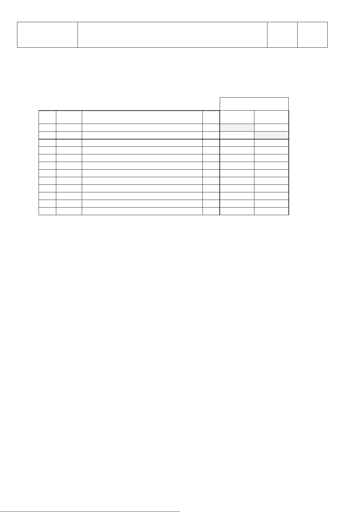
4.1.1 TECHNICAL DATA FOR TRANSPORTATION
GROSS WEIGHT [ kg ]
POS. CODE DESCRIPTION Q.TY 4m 5m
01 E118 Wooden box containing Globaljig System 1 750
02 E119 Wooden box containing Globaljig System 1 670
03 D495 Frame with lift 1 // 2470
04 D496 Frame with lift 1 2250 //
05 D497 Fixed pulling arm 1 370 370
06 D498 Articulated pulling arm 1 410 410
07 E121 Wooden box containing MacPherson 1 90 90
08 E409 Side runners + ramps 1 190 220
09 D475 Axle stands + crossbeam 1 60 60
10 D211 Electrical winch 1 30 30
11 E418 Trolley 1 70 70
12 E680 Control unit 1 120 120
GLOBALJIG INTERNATIONAL. srl grants the quality of the packaging material and the best
procedure concerning the correct location of the goods inside the packages.
All operations of loading and unloading packages, must be carried out using specific procedures
and methods as required by Health and Safety Regulations.
The assigned staff must wear the necessary protective clothing.
GLOBALJIG INTERNATIONAL. srl desclaims all responsibility for damage to people and/or
objects caused when not observing the warnings, the procedures and recommendations during
delivery, loading and handling.
4.1.2 PACKAGE CHECKING
With reference to the standard supply conditions, the transportation of the goods is always at
consignee’s risk, if not otherwise agreed .
Check at sight the delivered goods in the presence of the staff who made the transportation:
• The quantity of the packages.
• That no packge has been damaged or broken
• The presence of condensation or water inside the packages
It is very important to make this first check because the manufacturer will not accept
responsibility for any damage caused during carriage.
Issue.
08 / 2004
Pag.
6 - 42

INSTRUCTION MANUAL
Issue.
08 / 2004
5. INSTALLATION
The installation of the L.B. must be carried out by trained personnel only who must follow the
instructions contained in this manual.
The “Lifting Bench” is packaged as
shown in this picture .
Fig. 5-01
5.1. HOW TO MOVE THE PACKAGE
Once you have chosen the suitable area to
locate the equipment, use a fork lift truck
min. Capacity 2,0 tons to move the package
“L.B.”.Fig. 5-02
Please note: when positioning the “L.B.”
you should :
– Consider the vehicle’s side for lifting and lowering, called Front Side. The manufacturer plate
(pag.05) positioned on the first crossbeam of the bench deternines the Front Side.
– please read chapter 10 (Working Area) and chapter 14 (Overall Drawing).
After you have positioned the “L.B.”,
remove the wooden pallet from beneath the
lift. You can do this using standard jacks.
Fig. 5-03
During this lifting operation, you should protect the rack under the
WARNING
bench from any damage for this reason you should insert a wooden
spacer between the jack and the bench.
Proceeding with the utmost care, remove the
wooden pallet from underneath the “L.B.”
Fig. 5-04
Pag.
7 - 42
INSTRUCTION MANUAL
Issue.
08 / 2004
Pag.
8 - 42
5.2 UNPACKING
Cut the plastic straps and remove the four protective wooden angles for crossbeams and
measuring tapes.
Take out the two brackets, which are useful to fix the bench
with the base of the lift only during transportation.
Photo. 5-05
5.3 HOW TO FIX IT TO THE GROUND
– In order to arrange for the installation area you should refer to Overall Dimensions Drawing (Chapter
14)
– Before setting the equipment on the floor you should ensure that the ground is level and has suitable
bearing capability. It is recommended that it should be able to bear a total weight of 9.000 daN, with a
specific pressure of 0.50 daN/cm² and made of the correct consistency necessary to allow a proper
fixing of the anchoring plugs to the floor.
– The plugs supplied with the equipment are 6 (Ø 20x90 mm), with M12 screws.
– The plugs can be set and fixed only after electrical connection, because you must lift up the bench in
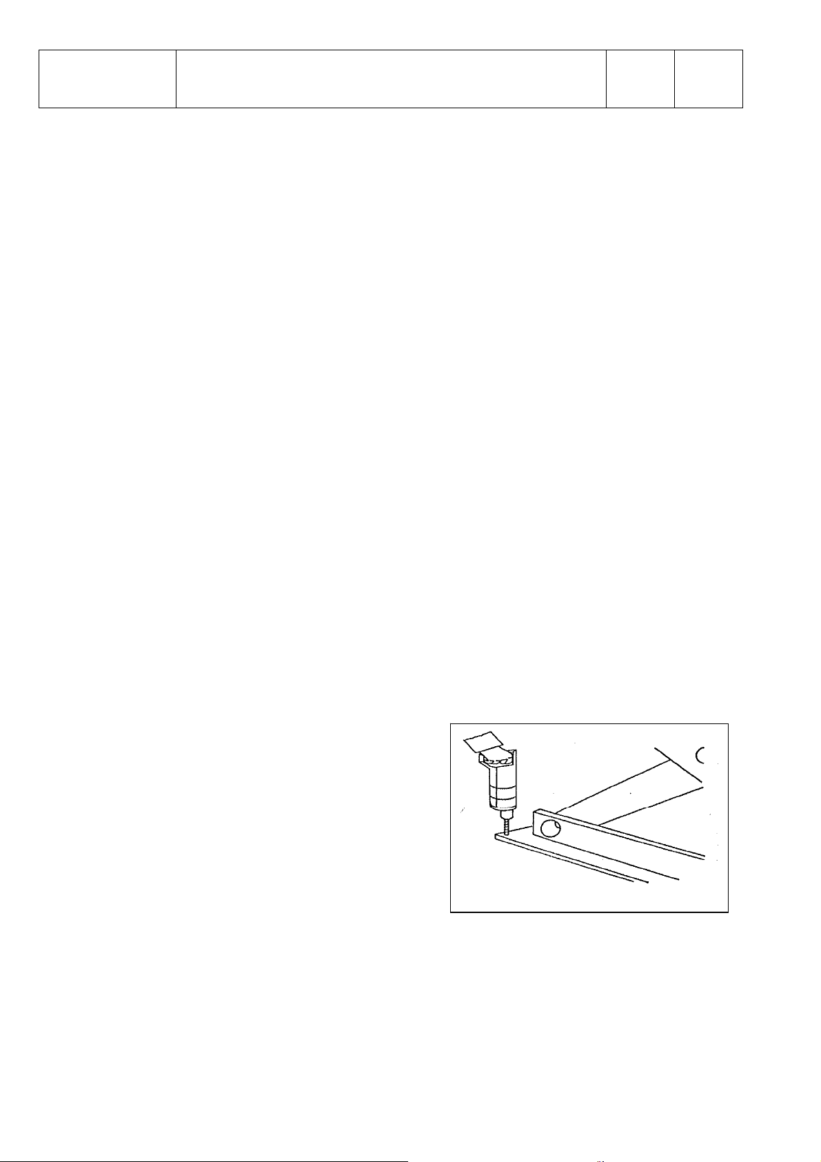
order to reach the floor and work with the drill. Fig. 5-06 Ð
How to proceed to fix the plugs:
– Using the holes of the base of the equipment as
a drilling jig, drill the floor with helicoidal point
Ø 20, to a depth of 95 mm..
– Clean the hole, insert the plugs, tighten the
screws.

6. COMMISSIONING
6.1 POWER UNIT CABINET
6.2 HYDRAULIC PLANT CONNECTION
6.3 PNEUMATIC PLANT CONNECTION
6.4 ELECTRICAL PLANT CONNECTION (low tension 24V)
6.5 ELECTRICAL PLANT CONNECTION (supplied from the network)
6.1 POWER UNIT CABINET
- Once you have positioned the bench, place the cabinet near its final position.
INSTRUCTION MANUAL
Issue.
08 / 2004
Pag.
9 - 42
On the back side of the cabinet you will find : (See picture 6-01 e 6-02)
• Tuboflex A70066, lifting jack supply
• Tuboflex A70067, inclination jack supply
• Feed pipe (blue) A70072, for safety bolt release jack
• Cable and plug for up-stroke end control.
Photo 6-01
Photo 6-
A70072
A70066
A70067
End stroke
cable

INSTRUCTION MANUAL
Issue.
08 / 2004
6.2 HYDRAULIC CONNECTION
6.2.1 To the liftting bench
- The cable and the pipes have a standard lenght of 5000 mm.
- Place in the provided setting-out the cable and the pipes to
the base of the lift (inclination jack’s side of the bench).
Picture 6-03Î
- Provide yourselves of the following keys :
- n° 1 of 18
- n° 1 of 19
- n° 2 of 22
- always working with two keys (as shown in the picture) untighten the caps placed on the
bracket and on the cylinder connection.
Photo Ô
6-04
Pag.
10 - 42
- untighten the caps at the end of the flexible feed pipes
coming out of the cabinet..
- Now connect the pipes to the connection on the bracket and
the connection on the cylinder.
We advise to proceed quickly in order to avoid a leak of oil from the
pipes.
Actually the plant is always supplied with oil because every lift is tested before shipment
- Tighten the connection feed pipes, always using two keys (see pictures below, in the correct
sequence)
Photo 6-05 Photo 6-06
INSTRUCTION MANUAL
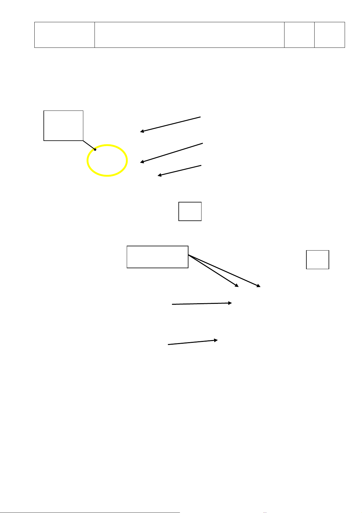
6.2.2 To the hydraulic power unit
6.2.2.1 see picture A
Issue.
08 / 2004
Pag.
11 - 42
See detail
(picture
B)
EMERGENCY
VALVES
Electric engine
Pump unit
Tank
A
B
Electro-valves(bench
inclination up/down)
Valves unit
DETAIL
VALVES UNIT

INSTRUCTION MANUAL
Issue.
08 / 2004
Pag.
12 - 42
6.2.2.2 Hydraulic Unit Table
Pump engine power kW 2,2
Number of poles of electric engine n° 4
Velocità di rotazione a vuoto g/1' 1500
Hydraulic pump type - Gears
Type of coupling Engine/Pump - Direct
Max hydraulic pressure bar 220
Pressione idraulica di esercizio bar 190
Oil tank capacity lt 12
Advised oil type SHELL TELLUS
SAE 32
or similar (see table below)
Hydraulic oils Table
Intervals of
Temperature
Up to 30°C From 30°C to 45°C Beyond 45°C
Standard viscosity
in Centistokes at
16-20 24-28 31-39
50°C
AGIP OSO 32 OSO 46 OSO 68
CASTROL HYSPIN AWS 32 HYSIN AWS 46 HYSPIN AWS 68
CHEVRON EP HYDR. OIL 32 EP HYDR. OIL 46 EP HYDR. OIL 68
ESSO NUTO H 32 NUTO H 46 NUTO H 68
IP IP HYDR. OIL 32 IP HYDR. OIL 46 IP HYDR. OIL 68
MOBIL D T E 24 D T E 25 D T E 26
TOTAL AZOLLA 32 AZOLLA 46 AZOLLA 68
 Loading...