

globalindustrial.ca
Instruction Manual Manual de Instrucciones Manuel d'instruction
Distribucion Industrial Globales S DE RL DE CF
Customer Service
US: 1-800-645-2986
Servicio de atención al Cliente
México: 01.800.681.6940
Service à la clientèle
Canada: 888-645-2986
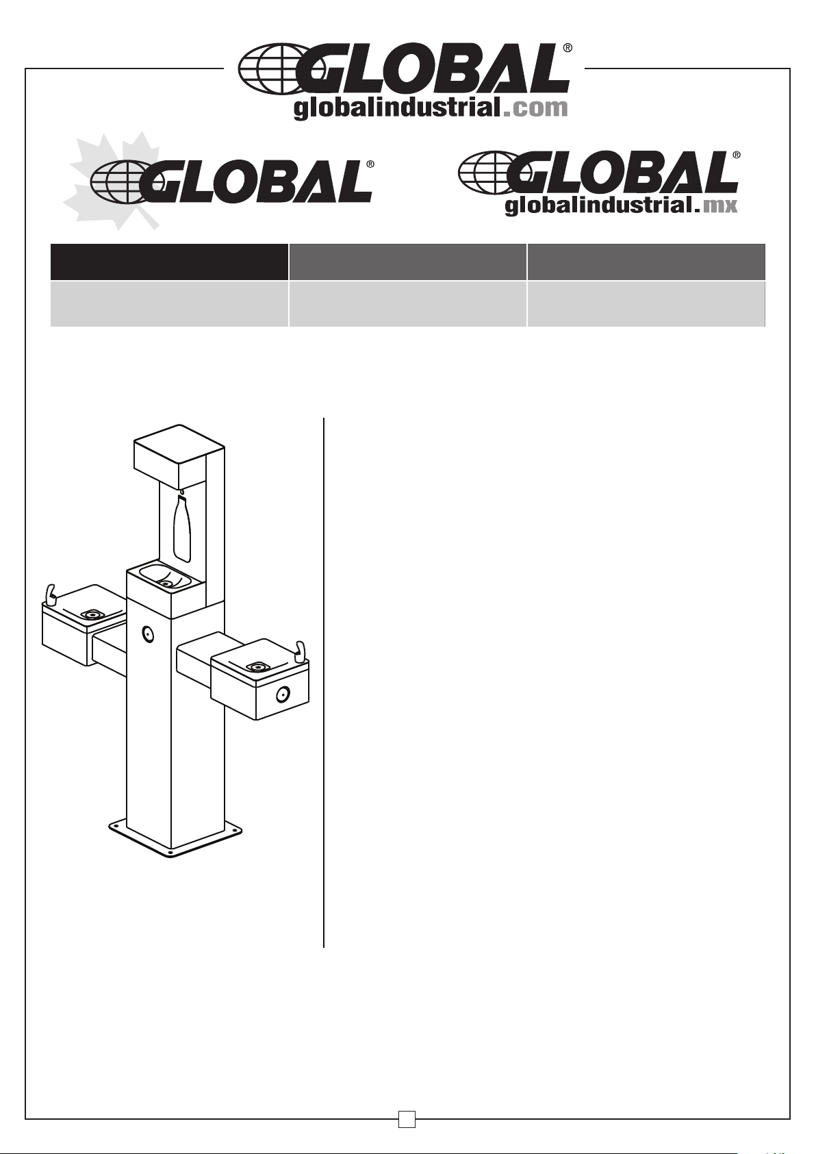
Outdoor Bi-Level Drinking Fountain w/ Bottle Filling Station
WARNING
• All installation work must be performed by authorized
service personnel.
• Two or more people are recommended to lift and
install the unit.
• To avoid the risk of property damage and/or personal
injury, ensure the mounting surface is adequate to support
400 lbs.
• Check local codes for plumbing requirements prior
to installation.
• Refer to Rough-In Guide (page 4) prior to installation.
• Thoroughly flush all water supply lines of all foreign
matter before connecting to the fixture.
• Check for any leaks before use.
• DO NOT attempt to repair or replace any part of this
fountain unless it is specifically recommended in this
manual. All other services should be referred to a
qualified technician.
• For use with clean, clear potable drinking water only.
• Shut-off water supply during installation to reduce the
risk of water damage.
• Freezing Caution: Before freezing temperatures occur,
refer to the Draining and Winterization section of this
manual (page 12) for proper preparation.
Models 761220, 761220BK,
761220BL & 761220GN
• Installation of a trap on the water drain line may be
necessary; remove trap before winterization draining.
• Failure to follow safety warnings and/or
installation instructions will void warranty.
Note: This unit is designed to be installed on the surface of an existing or new concrete slab.
Included are the necessary vandal-resistant stainless steel bolts and washers needed
to anchor this unit. Installer must provide a 1-1/2” PVC drain line (if applicable) and water supply
line. All connections are made inside the item through the access doors, as shown in the drawings.
It is recommended to install a shut-off valve (not included) on the water supply.
1
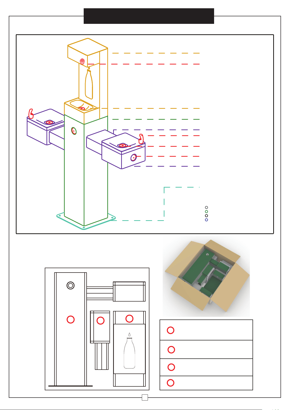
Outdoor Bi-Level Drinking Fountain w/ Bottle Filler
BOTTLE FILLER
SPOUT
DRAIN PAN
PEDESTAL
PEDESTALARM
BUBBLER
DRAIN
Instruction Manual
PUSH BUTTON
DRINKING FOUNTAIN
BASE
COLOR OPTIONS:
SS316
SS316 GREEN
SS316 BLACK
SS316 BLUE
WWW.GLOBAL INDUSTRIAL. COM
2
3
1
1
BOTTLE FILLER
2
PEDESTAL
3
DRINKING FOUNTAIN
4
HARDWARE BAG
2
SPECIFICATIONS
Features :
316 Stainles s , Lam inar Flow, Heavy Duty, Vandal Resistant
Finis h: SS Finish, Black(BK), Blue(BL), Green(GN)
Power: No Electrical Required
Bubbler Vandal Resistant
Activation Type: Push Button
Mounting Type: Floor Mount/Free Standing
Product Dimens ions: 47-3/4"L x 14"W x 60-1/4"H
Weight: 112 lbs .
Installation Location: Outdoor
No. of Stations: 3
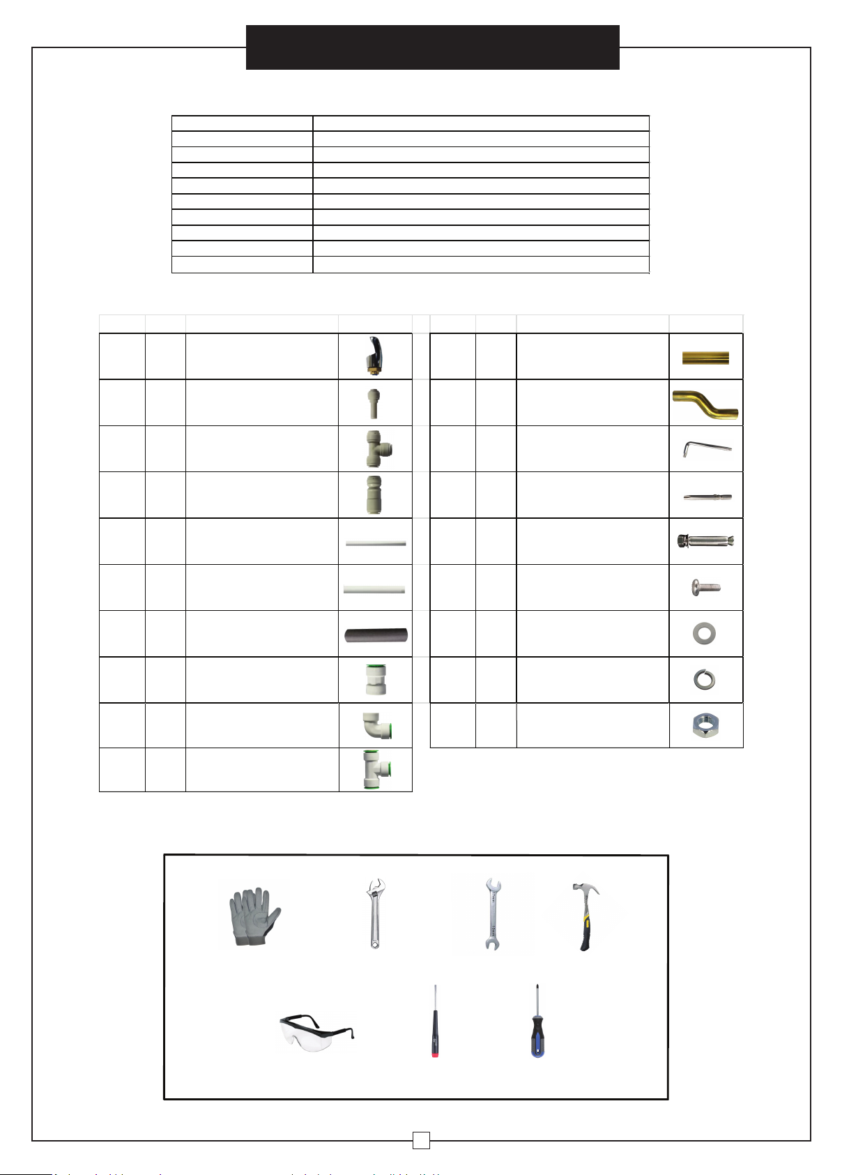
Ref. Qty. Descrip�on Ref. Qty. Descrip�on
PART BREAKDOWN
Outdoor Bi-Level Drinking Fountain w/ Bottle Filler
Instruction Manual
P1 2 Bubbler
P2 3 Inlet Adapter
P3 2
P4 1
P5 6
P6 3
Union T-Connector
Straight Flow Check Valve
1/4" O.D. Water Inlet
(1) 39-1/4”, (2) 25-1/2”, (3) 6-1/4”
3/8" O.D. Water Inlet
(1) 21-3/4”, (1) 4“, (1) 2”
P7 9 Pipe Insula�on
P8 1
P9 2
Straight Drain Connector
Elbow Drain Connector
P11 4
P12 1
H1 1
H2 1
H3 4
H4 8
H5
H6
H7
Drain Tubing
(2) 16-3/4”, (1) 23”, (1) 3-3/4“
Offset Drain Tubing
Torx Key Wrench
Torx Drill Bit
Anchor Kit
M6 x 10 Pan Head Screw
4
4
4
M10 Washer
M10 Lock Washer
M10 Nut
P10 2 T-Shape Drain Connector
REQUIRED TOOLS:
Safety Gloves
Safety Glasses
Adjustable Wrench
Small Flathead
Screwdriver
15-17mm
Wrench
3
Hammer
Phillips-Head
Screwdriver
Outdoor Bi-Level Drinking Fountain w/ Bottle Filler
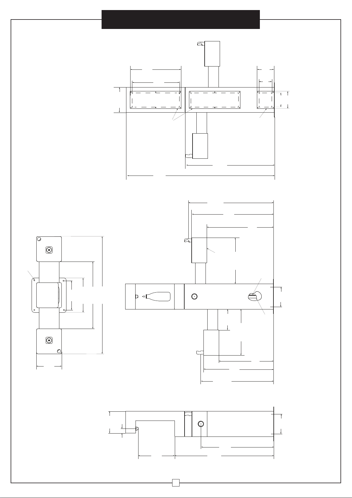
20 1/2''
526mm
20''
511mm
10 1/4 ''
260mm
5 1/2''
133mm
7''
177mm
Instruction Manual
7''
177mm
5 1/2''
146mm
1/2''
12mm HOLES (4)
60 1/4''
1531mm
27''
689mm
B-2
A
FINISHED FLOOR
• Actual product configuration may vary based on model ordered.
• See Page 12 for Draining and Winterization
B
36 1/2''
922mm
34 1/2''
880mm
ORIFICE
HEIGHT
33 1/4''
847mm
C
18 1/2''
475mm
14''
355mm
11 1/2''
300mm
10''
260mm
Rough-In Guide
27''
691mm
47 1/2 ''
1211mm
9''
225mm
1.8''
46mm
16''
376mm
40''
1023mm
29''
755mm
8 1/2''
215mm
28 1/2''
ORIFICE
HEIGHT
29''
753mm
18 1/2''
475mm
723mm
22''
565mm
1-1/2''
WASTE
8 1/4''
210mm
INSIDE OPENING
8 1/4''
210mm
INSIDE OPENING
LEGEND:
A = 3/8” O.D. UNPLATED COPPER TUBE CONNECT - SHUT-OFF VALVE BY OTHERS
B = ACESS PANEL (7” X 20”)
B-2 = ACCESS PANEL (7” X 7”)
C = REMOVABLE BOTTOM COVER
4

Instruction Manual
Outdoor Bi-Level Drinking Fountain w/ Bottle Filler
INSTALLATION
• It is recommended that 2 or more people install this unit.
• This fountain must be mounted on a solid, flat surface with adequate strength (concrete
pad recommended) capable of supporting 400 lbs.
• Locate and install plumbing through ground as required. Refer to Rough-In Guide (page 4)
for proper location and correct plumbing.
• Install a drainable shut-off valve (not included) if in a freezable environment.
• Installation of a trap on the water drain line may be necessary; check local plumbing codes.
WARNING: The fountain is rated for inlet water pressure of 20-105 PSI. A pressure reducing
regulator should be used if the inlet water supply exceeds 105 PSI. Any damage caused by
reason of connecting this product to supply line pressure higher than 105 PSI will void warranty.
1. REMOVE ACCESS PANELS
To gain access to the drain and water line connections, remove all access panels detailed below
using the provided torx key wrench (H1) or torx drill bit (H2) to remove all (32) M6 x 10
flat-head anti-theft screws on back side of the bottle filler and pedestal, as well as the underside
of the drinking fountain pans:
Flat-head anti-theft screw
M6 x 10 (qty 32)
REMOVE
REMOVE
REMOVE
REMOVE
REMOVE
5

2. INSTALL BUBBLERS
Outdoor Bi-Level Drinking Fountain w/ Bottle Filler
Instruction Manual
2a. Unscrew and remove
nut and washers from
Bubblers (P1).
2b. Locate the hole on the drinking
fountain pan surfaces. Align and
sanwich with the two washers and
2c. Bubblers are now
properly installed.
tighten the nut to secure the bubbler.
3. MOUNT PEDESTAL TO GROUND
• Locate and install plumbing through ground as required. Refer to Rough-In Guide (page 4)
for proper location and correct plumbing.
• This unit is designed to be installed on the surface of an existing or new concrete slab,
capable of supporting 400 lbs.
Position fountain base over plumbing and
secure to ground using provided anchor
kit (H3) mounting hardware (x4).
(H3) Anchor kit consists of:
- (4) M10 Nuts
- (4) M10 Lock Washers
- (4) M10 Standard Washers
- (4) M10 Anchors
H3
(qty 4)
Nut
Lock Washer
Standard Washer
Anchor
6

Outdoor Bi-Level Drinking Fountain w/ Bottle Filler
4. ATTACH BOTTLE FILLER TO PEDESTAL
4. ATTACH BOTTLE FILLER TO PEDESTAL
Using a phillips-head screwdriver, assemble the bottle filler to the pedestal
using H4 (x8) M6 x 10 pan head screws.
Instruction Manual
5. ATTACH DRINKING FOUNTAIN TO PEDESTAL
Assemble to the drinking fountain to the
pedestal using H5 (x4), H6 (x4) and H7 (x4)
hardware. Tighten all nuts securely using
an adjustable wrench.
H4
(qty 8)
H5
(qty 4)
H6
(qty 4)
H7
(qty 4)
7
Outdoor Bi-Level Drinking Fountain w/ Bottle Filler
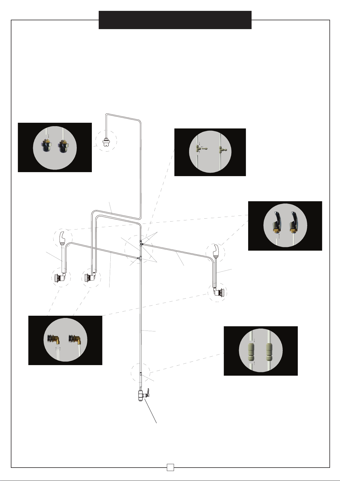
6. CONNECT WATER INLET LINES
• Install a shut-off valve (not included) on the water supply.
• All water connections and drains must comply with local codes.
Though the rear access windows, connect water inlet lines as illustrated below:
Instruction Manual
Connect (P5) to Spout
P5
(6-1/4”)
P5
(39-1/4”)
P6
(2”)
P5
(25-1/2”)
P2
Connect Inlet Adapter (P2) to
P2
P3
P6
(21-3/4”)
Union T-Connector (P3)
P5
(25-1/2”)
P5
(6-1/4”)
Connect (P5) to Bubbler
Connect (P5) to Push Button
P4
INSTALL SHUT-OFF VALVE
(NOT INCLUDED)
8
Connect (P6) to Straight
Flow Check Valve (P4)
(See Fig. 1 on next page)

Outdoor Bi-Level Drinking Fountain w/ Bottle Filler
WATER INLET LINE CONNECTION BREAKDOWN:
Instruction Manual
P5
(39-1/4”)
P6
(2”)
SIDE VIEW
P6
(21-3/4”)
P5
(25-1/2”)
P6
(2”)
FRONT VIEW
P2
P2
P5
(25-1/2”)
P3
P5
(6-1/4”)
P4
Install Shut-off Valve
(Not Included)
WATER
SOURCE
P4: Straight Flow Check Valve: All Water Inlet Connec�ons:
3/8” O.D. TUBE CONNECT
COLD WATER SUPPLY
NOTE: WATERFLOW DIRECTION
FIG. 1
OPERATION OF QUICK CONNECT FITTINGS
SIMPLY PUSH IN
SIMPLY PUSH IN
TUBE TO ATTACH
TUBE TO ATTACH
A B C
FIG. 2
TUBE IS SECURED
TUBE IS SECURED
IN POSITION
IN POSITION
B CA
PUSH IN COLLET
PUSHIN COLLET
TO RELEASE TUBE
TO RELEASE TUBE
PUSHING TUBE IN BEFORE
PULLING IT OUT HELPS TO
RELEASE TUBE
• If drinking fountain is being installed in areas where cold temperatures may occur, wrap
pipe insulation (P7) around all water inlet lines.
• Installation of a trap on the water drain line may be necessary; check local codes.
Always remove trap before winterization draining.
CAUTION: Before freezing temperatures occur, see Draining and Winterization section
of this manual (page 12) for proper preparation.
9

Instruction Manual
Outdoor Bi-Level Drinking Fountain w/ Bottle Filler
7. CONNECT WATER DRAIN LINES
• All water connections and drains must comply with local codes.
• Through the rear access windows, connect water drain lines as illustrated below.
NOTE: All drain lines attach with quick connect connections.
• Installation of a trap on the water drain line may be necessary; check local codes.
Connect (P9) to Drinking
Connect (P8) to Bottle
Filler Drain and insert (P12)
P6
Fountain Drain and insert (P11)
P9
Connect (P9) to Drinking
Fountain Drain and insert (P11)
P11
(3-3/4”)
P11
(16-3/4”)
P11
(16-3/4”)
P12
P9
P10
Connect all 3 Drain Tubes
to (P10)
P11
(23”)
Confirm with local codes for
trap and other drainage requirements
10

Outdoor Bi-Level Drinking Fountain w/ Bottle Filler
WATER DRAIN LINE CONNECTION BREAKDOWN:
Instruction Manual
P12
SIDE VIEW
P8
P11
(3-3/4”)
P11
(16-3/4”)
FRONT VIEW
P11
(16-3/4”)
P10
P9
P11
(23”)
Confirm with local codes for
trap and other drainage requirements
Note: Turn on water supply and check all connections for leaks and proper operation.
Reinstall all (5) access panels using the (32) M6 x 10 flat-head anti-theft screws preciously
removed from the fountain.
WARNING: Flush all water supply lines thoroughly before initial use.
11

Instruction Manual
Outdoor Bi-Level Drinking Fountain w/ Bottle Filler
START-UP
Initial water flow may have sputter due to air in the water lines; this will be eliminated
once air is purged from all water lines. Press and hold the push button until a steady
water stream is achieved.
STREAM HEIGHT ADJUSTMENT
To adjust the water stream height, insert a small flathead screwdriver through the access
hole in the center of the push button and turn the adjustment screw. Turn clockwise to raise
the stream height and counterclockwise to lower the stream height. For best adjustment,
the stream should be approximately 1-1/2" above the top of the bubbler, (see FIG.3).
1 1/2''
FIG. 3
CAUTION: The fountain is rated for inlet water pressure of 20-105 PSI. A pressure reducing
regulator should be used if the inlet water supply exceeds 105 PSI. Any damage caused by
reason of connecting this product to supply line pressures lower than 20 PSI or higher than
105 PSI will void warranty.
DRAINING AND WINTERIZATION
• Before freezing temperatures occur, turn off the water at the shut-off valve, disconnect
the water supply line tubing and blow out lines. Press down on push button to release any
air pressure that may remain in the lines.
• Remove trap before winterization draining.
• DO NOT allow water lines to freeze. Cracked or broken components due to freezing are
not covered by warranty.
12
 Loading...