

Page 1
globalindustrial.ca
User's manual Manual del usuario Manuel de l'utilisateur
Customer Service
US: 1-800-645-2986
Servicio de atención al Cliente
US: 1-800-645-2986
Service à la clientèle
Canada: 888-645-2986
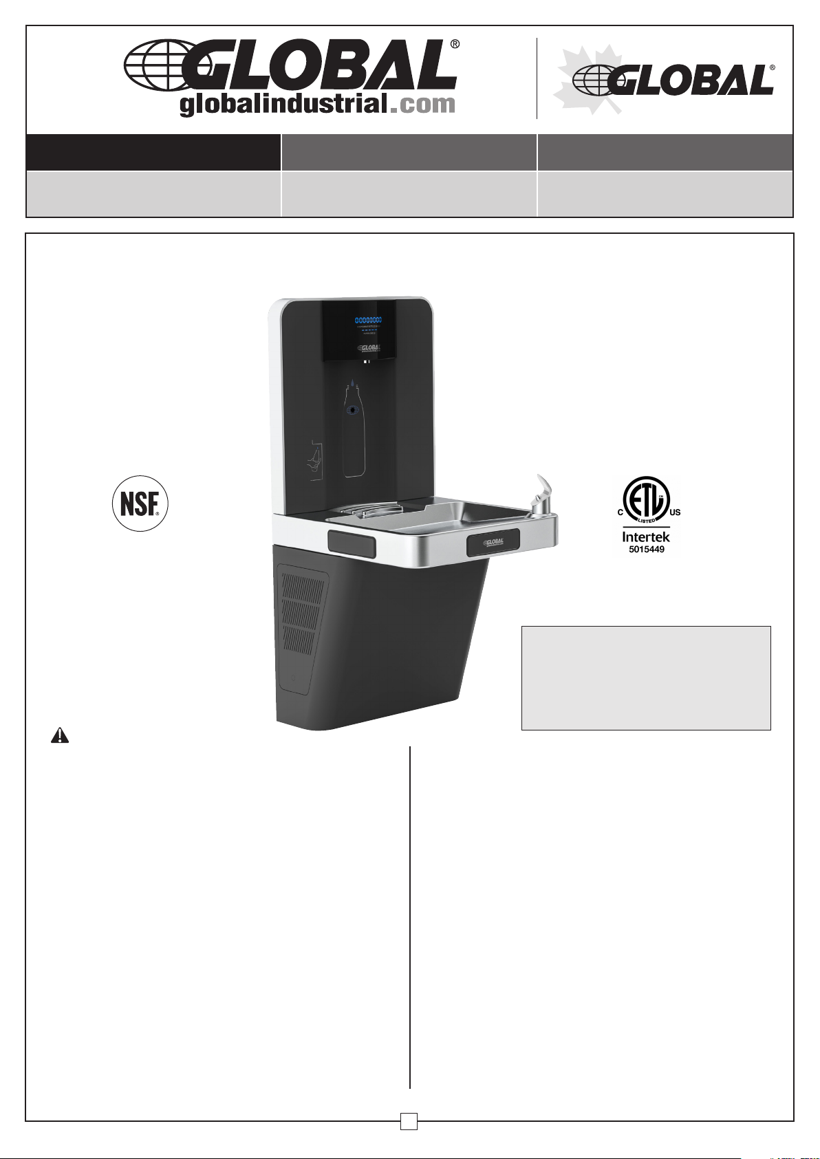
Wall Mounted Water Bottle Refilling Station
Model 761218
WARNING
• Keep compressor in upright position for 24 hours
before water connections and initial power-on. Failure
to do so will void warranty.
• For indoor commercial use only.
• All installation work must be performed by authorized
service personnel.
• Two or more people are recommended to lift and install
the unit.
• To avoid the risk of property damage and/or personal
injury, mount the unit to a flat finished wall surface with
adequate support.
• Check local codes for plumbing requirements prior
to installation.
• Prior to initial installation, install a shut-off valve (not
included) from the water supply.
• Thoroughly flush all water lines and fittings of all foreign
matter before connecting to the cooler. Failure to do so
will void warranty.
• Check for any leaks before initial operation.
• DO NOT attempt to repair or replace any part of your
appliance unless it is specifically recommended in
this manual. All other services should be referred to a
qualified technician.
Read this manual thoroughly prior to
installation, operation or maintenance.
Keep these instructions in a safe location
for future reference. For questions, visit
globalindustrial.com or contact Customer
Service at 1-800-645-2982.
• For use with clean, clear potable drinking water only.
• Shut-off water supply during installation to reduce risk
of water damage.
• Ensure proper ventilation by allowing appropriate
clearance of housing louvers to the wall on each side
of the cooler, as specified in rough-in guide.
•
NEVER wire the compressor directly to an electrical supply.
• DO NOT allow children to play with the appliance.
• Interior of unit may contain sharp edges. Wear gloves
when handling or servicing unit.
•
Failure to follow installation instructions will void warranty.
Note: These fixtures are intended for indoor commercial
use only. Do not expose to freezing temperatures.
The grounding of electrical equipment to water lines is
a common procedure. This grounding may be in the
building or occur away from the building. This grounding
can cause electric feedback into the water cooler
creating an electrolysis which creates a metallic taste or
causes the water metal content to increase. Connect to
water supply using non-conductive materials.
1
052120
Page 2
Wall Mounted Water Bottle
Refilling Station
User's Manual
Risk of Electrical Shock
• Disconnect power before servicing unit.
• Electric supply must be identical in voltage, cycle and
phase to those specified in the specifications below.
Unit must be plugged into a GFCI outlet.
• Always pull the plug – not the cord – when disconnecting
from the outlet
• DO NOT use if the power cord is worn or damaged.
Power cords should only be replaced by qualified
service technicians using genuine replacement parts.
• Check local codes for electrical requirements.
• DO NOT disassemble or modify unit.
• Use Global Industrial filters only – Model 670336
Voltage/Hertz 115V/60Hz
*Chilling Capacity 8.0 GPH
Full-Load Amps 1.9 Amps
Rated Watts 185 W
Filter Capacity 4750 or 3000 Gallons
Quick-Fill Rate 1.0 GPM
Water Flow Laminar
Overall Dimensions 18
1
/
"W x 16"D x 37
8
13
/
"H
16
UL399 and CAN/CSA 22.2 No. 120
Certification
ADA Compliant
ANSI/NSF 372
ANSI/NSF 42 and 53 (Filter)
* At 46° - 54° (F) against ambient air temperature of 77° (F)
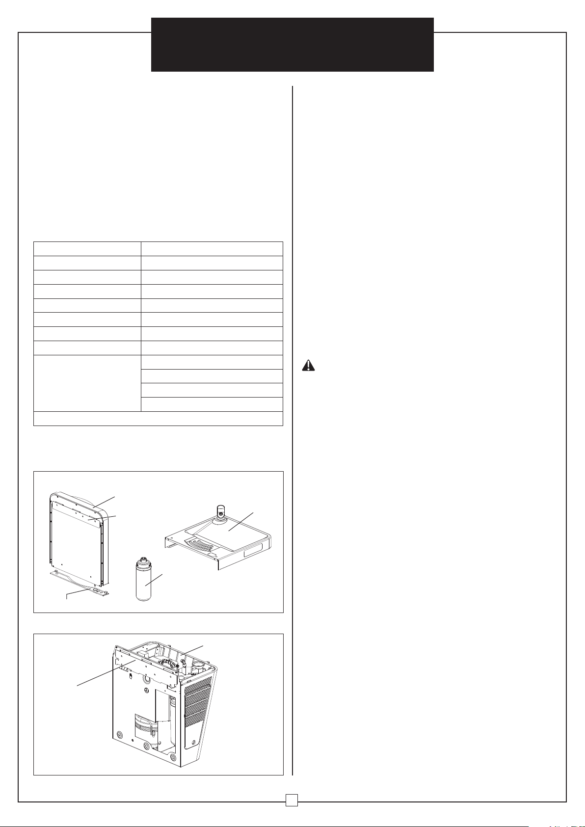
Package Contents:
Box 1 - 761213 Top Assembly for Bottle Filler
Bottle Filler
Top Assembly
Mounting Bracket
(attached to rear)
Stainless
Steel Pan
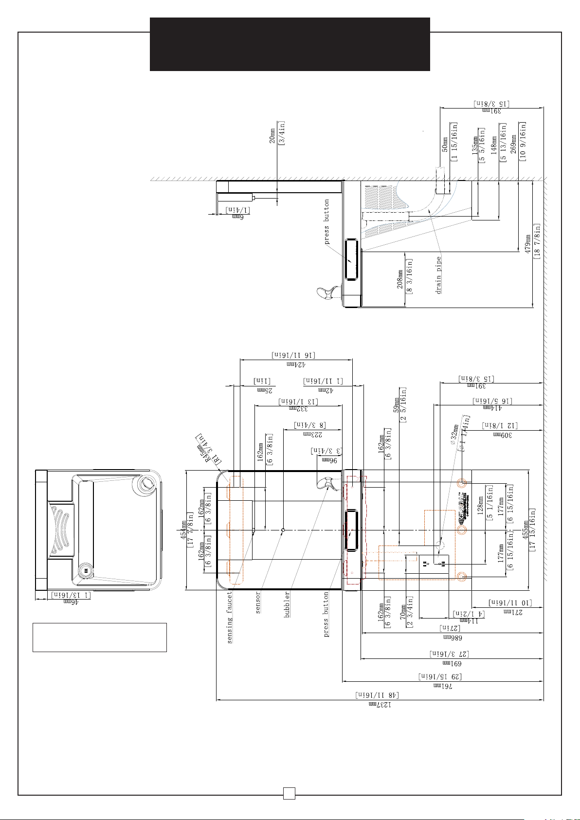
Note:
• Prior to installation, consult with local, state, and federal
codes for proper mounting height.
• All installation and service should only be performed by
authorized personnel.
• Dimensions shown below comply with ADA requirements
at time of printing.
• Allow 4" minimum clearance on both sides to allow for
proper ventilation through cabinet louvers.
• Thoroughly flush all water lines and fittings of all foreign
matter before connecting to the Cooling System.
Failure to do so will void warranty.
Required Tools:
1. Safety Glasses
2. Safety Gloves
3. Electric Drill
4. Phillips Head Screwdriver
5. Flathead Screwdriver
6. Tape Measure
7. Pencil
8. Level Device
9. (11) 75-lb. Capacity Flat Head Wall Anchors
(appropriate for your wall type)
10. (11) Flat Head Anchor Screws
WARNING
• Review manual thoroughly and verify rough-ins before
installation. Keep these instructions in a safe location
for future reference.
• Keep compressor in upright position for 24 hours
before water connections and initial power-on. Failure
to do so will void warranty.
• It is recommended to assemble this product on a
tabletop or bench.
• Fixture must be mounted to a flat finished industry
standard wall surface. The wall surface must have
adequate support to secure the fixture, with the
addition of wall anchors (not included) if required.
• All receptacles must be wired to a GFCI protected
circuit. Fixture must be earth grounded per National
Electric Code (NEC).
• Inspect fixture and all parts for damage.
Water
Filter
Rubber Gasket
Not Pictured:
Hardware Bag
Mounting Stencil
Box 2 - 761212 Cooling System for Water Fountain
Cooling System
Mounting Bracket
(attached to rear)
2
Page 3
Wall Mounted Water Bottle
Refilling Station
User's Manual
Check local codes for plumbing
requirements prior to installation.
3
Page 4
Assembly Instructions
Wall Mounted Water Bottle Refilling Station
Model 761218
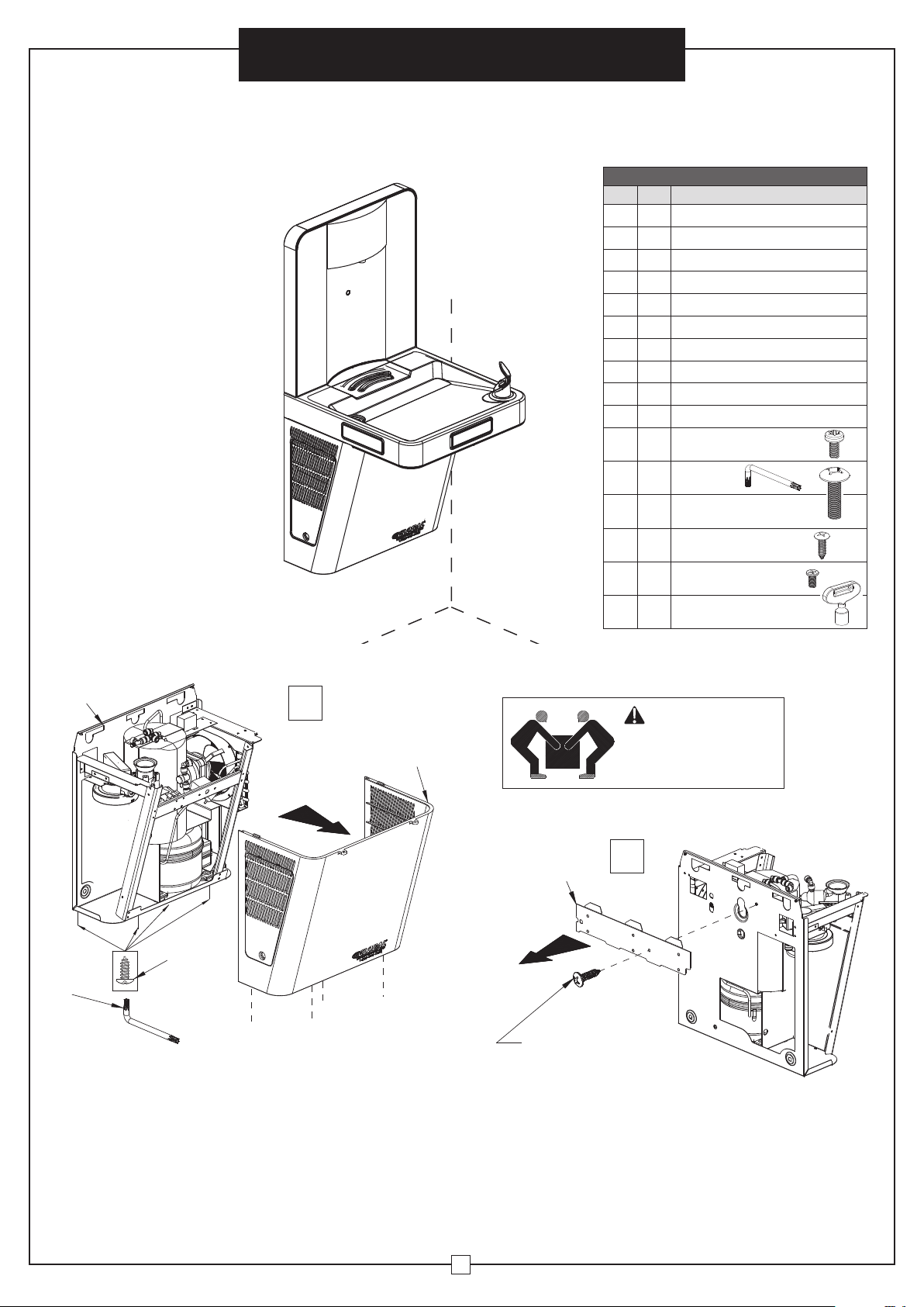
CONTENTS
Ref. Qty. Description
1 1
2 1
3 1
4 1
5 1 Back Plate
6 1 Top Mounting Bracket
7 1 Gasket
8 1 Stainless Steel Pan
9 1 Water Filter
10 1 Filter Access Door
H1
H2
H3
H4
H5
Cooling System
Lower Cover
Bottom Mounting Bracket
Bottle Filler Top Assembly
M4 x 8mm Lg. Torx
4
Pan Head Anti-Theft Screw
1 Torx Key
M6 x 20mm Lg. Phillips
2
Truss Head Screw
#4 x 1/2 Lg. Phillips
4
Pan Head Screw
M4 x .7x 8mm Lg.
6
Phillips Flat Head Screw
H2
H6
1 Filler Access Door Key
1
1
WARNING
Assembly and installation
2
of equipment should be
performed by 2 people.
3
2
H1
Discard after removal
Remove Lower Cover
Using the Anti-Theft Screw Star Key, remove the (4)
screws at the bottom of the Lower Cover. Set Lower
Cover aside and save screws for reinstallation.
Remove mounting bracket
Using a Phillips head screwdriver, remove the
Mount Bracket from the rear of the Cooling
System by removing (1) screw. Discard screw
and set bracket aside.
4
Page 5

Wall Mounted Water Bottle
Refilling Station
3 4
Assembly Instructions
6
4
Discard after
removal
Remove top mounting bracket
Using a Phillips head screwdriver, remove the
Top Wall Mount Bracket fastened to the rear of
the Bottle Filler Top Assembly by removing (1)
screw. Discard screw and set bracket aside.
5
5
4
7X
Remove back plate
Using a Phillips head screwdriver, remove Back Plate
from the rear of the Bottle Filler Top Assembly by
removing (3) screws. Set Back Plate aside and save
screws for reinstallation.
5
7
Attach gasket
Attach Gasket to the bottom of the Bottle Filler
Top Assembly as shown.
Note: Ensure gasket is seated properly and
lies flat so there are no gaps.
6
H3
Stainless
Steel Pan
Attach bottle filler
Flip Bottle Filler Top Assembly right-side-up and carefully
feed connections though the Stainless Steel Pan hole.
Ensure gasket is seated properly and lies flat. Attach
Bottle Filler Top Assembly to the Stainless Steel Pan
using (2) H3 screws.
4
8
5
Page 6

7A
#2
Wall Mounted Water Bottle
Refilling Station
Connect Water Lines
• Connect water line (#1) from the Stainless
Steel Pan to the Water Control Valve (#1) in the
Cooling System.
• Push line until locked into place.
• Connect the water line (#2) in the Bottle Filler
Top Assembly to the Water Control Valve (#2)
in the Cooling System.
• Push line until locked into place.
#1
Connect Wire Connectors
•
Connect white Activation Connector (C) to
Power Supply (C) in the Cooling System.
• Connect white Activation Connector (A)
7B
to Power Supply (A).
• Connect the 2 Activation Connectors (B)
to the Solenoid Valve (B).
Assembly Instructions
7C
B
Reset Button
Connection
A
C
Solenoid
valve
B
Reset Button
Connection
H4
Attach stainless steel pan
• Feed the Reset Button Connection through
the Cooling System's frame and carefully
lower the Stainless Steel Pan on top of the
Cooling System.
• Attach the Stainless Steel Pan to the
Cooling System using (2) H4 screws.
6
CAUTION
Avoid crossing wires
against sharp edges
Page 7

8
Wall Mounted Water Bottle
Refilling Station
Attach back plate
9X
H5
Reattach the Back Plate onto the
rear of the Bottle Filler Top Assembly
using the (3) screws previously
removed, plus (6) (H5) screws.
Unit is now ready for mounting.
Assembly Instructions
See wall
mounting
template
9
10
Level
Note: To comply with ADA requirements, the base of stencil must
be installed 11" to 143/4" from the floor. See Rough-in Guide for
additional ADA requirements.
Note: Before installing brackets to the wall, assure power source,
water line and drain aligns to opening on unit
Attach mounting brackets to wall
• Affix stencil with tape to appropriate wall. It is recommended to use a
level to ensure the stencil is hung straight horizontally.
• Drill (9) holes appropriate for the wall anchors (75 lb. minimum each)
as indicated on the top and bottom mounting brackets on the stencil.
Use appropriate anchors for your wall type.
• Drill 2 holes appropriate for the wall anchors (75 lb. minimum each) as
indicated on the bottom support holes on the stencil. Use appropriate
anchors for your wall type.
• Remove stencil from the wall and install top and bottom brackets onto
the wall using appropriate anchors.
Hanging assembled unit to wall
• Carefully hang assembled bottle filler onto
the wall by lowering onto both top and
bottom wall mount brackets.
CAUTION
Once assembled, do not lift unit by Bottle Filler
Lift
Points
7
Top Assembly. Use two people when lifting.
Always wear work gloves when lifting
Page 8

11
Assembly Instructions
Wall Mounted Water Bottle
Refilling Station
Valve Control
• Ensure both water control valves are turned to the
closed position.
• Attach 2 screws (not included) through the frame
of the Cooling System and into the bottom support
holes previously drilled into the wall.
• Connect the building's water supply to the Filter
Head Connection. This connection must be made
through the back of the Cooling System.
• Connect the internal drain line to the building's
external drain. This connection must be made
through the back of the Cooling System.
Water Control Valves
Closed
Connect filter
head to water
supply
Wall mounting
hardware not
provided
Closed
12
Install water filter
• Remove the receiver protective cover from the
water filter.
• Insert filter into the filter head by turning clockwise
until locked into place.
• Turn both water control valves to the open position.
• Check all connections for leaks. If leaks are
detected ensure all connections are tight and are
fully inserted.
• Turn on buildings water supply and
13
Check local codes for plumbing requirements prior
to installation.
check all connections for leaks.
• Fix any leaks before continuing.
• Plug power cord into outlet.
Water Filter
9
Counter clockwise to remove
Clockwise to install
Open
Turn on both
water control valves
(CHECK FOR LEAKS)
Note: If cooling system is on its side or back for more
than 10 minutes, allow it to stand in the upright
position for 24 hours before water connections and
initial power-on.
Open
8
Page 9

Wall Mounted Water Bottle
Refilling Station
14
10
H6
• Remove the filter access door using
the provided key.
WARNING
Risk Of Electrical Shock
• Turn off power prior to performing any maintenance.
• Verify supply voltage accuracy.
• Ensure all electrical and grounded connections are in
accordance with the National Electrical Code and any
other applicable local code requirements.
• All wiring connections should be capped with approved
wire connectors.
The warnings, precautions, and instructions discussed
cannot cover all possible conditions and situations that may
occur. Failure to heed these warnings may result in property
damage and personal injury.
General Safety Information
• To reduce the risk of property damage, personal injury,
electric shock, falling equipment, and other hazards
please read all instructions and warnings.
• Installation, service, and maintenance should be
• All parties must follow proper safety procedures and
precautions at all times.
• Do Not Install Damaged Products!
15
2
H1
H1
Reattach lower cover
• Reattach the Lower Cover to the Cooling System
using (4) H1 anti-theft screws.
• Fasten the Lower Cover to the bottom of the
Stainless Steel Pan using (2) H1 anti-theft screws.
CAUTION
Make sure all wires are
tucked in before attaching
cover plate to lower cover.
16
Connect reset cable to activation button
• Connect the Reset Button connection cable to
the Activation Buttons located at the top of the
filter access door frame.
•
Reinstall the filter access door using the provided key.
• Unit is now ready for use.
Reset button connection
9
Page 10

Wall Mounted Water Bottle
Refilling Station
User's Manual
Operation
Note: Initial water flow may have sputter due to air in the
water lines; this will be eliminated once air is purged from
all water lines.
To operate bottle filler, verify proper dispensing by
placing bottle, hand or any opaque object in front of the
sensor area.
Adjusting Settings
Water Flow Pressure: Adjust the water flow pressure as
needed by turning the water control valve. Turn clockwise
to decrease the water pressure, or counterclockwise to
increase the water pressure.
Note: When adjusting, aim water flow to the center of the
stainless steel pan.
Note: Initial dispenses may have air in line which may
cause a sputter. Allow a few seconds for air to be purged
from the water line.
Water Temperature: Machine comes with a preset water
temperature of around 45°F. If a different temperature is
required, remove Lower Cover and access the thermostat
on the front housing frame. Using a flathead screwdriver, turn
thermostat screw clockwise to lower temperature setting.
Note: Please allow 5-10 minutes for water temperature
to change.
To operate drinking fountain, push front or side activation
buttons on the stainless steel pan to dispense cooledfiltered water from the bubbler.
When unit is plugged in for the first time, the LCD will
display: 00000000. If not, the filter monitor needs to be
reset – refer to Resetting Filter Monitor section below.
Installing/Replacing Filter
1. Remove filter access door on the lower cover using the
provided key (H6).
2. Grasp old filter and turn counterclockwise to remove
from the filter head.
H6
3. Press and hold ENTER button for 5 seconds to reset
this bottle counter number to zero 00000000.
4. Tap SET button 1 time or wait 5 seconds to return to
standard bottle counter view.
Replacement Filters: Model 670336
For more information visit: globalindustrial.com or
call 1-800-645-2982.
Clockwise
To Install
Counterclockwise
To Remove
10
Page 11

Wall Mounted Water Bottle
Refilling Station
Programming Settings
Accessing the Programming Buttons:
To access the programming buttons, open the filter
access door on the lower cover using the provided key
(H6). The two program buttons are located on the top of
the filter access door frame.
Programming
Buttons:
User's Manual
Enter
Set
Resetting Filter Status
1. Press and hold ENTER button for 5 seconds, until
Reset Ft is displayed on the LCD screen.
2. Tap SET button to select.
3. Press and hold SET button for 5 seconds to reset filter
status. The LCD screen will display 0000 and the LCD
filter status bar will reset to the full 5 bars.
Select Filter Size
1. Press and hold ENTER button for 5 seconds until
Reset Ft is displayed on the LCD screen. Tap ENTER
button. The LCD screen will display: Ft Size.
2. Tap SET button to access Filter Size mode.
3. Tap SET to toggle between 1500, 3000, and 3600
gallon filter size options, or No Ft to bypass filter size
if a filter is not being used. Note: For filter capacities
higher than 3600 gallons, select 3600.
4. Tap ENTER button to confirm your filter size.
Resetting Bottle Counter:
1. Press and hold ENTER button for 5 seconds.
2. Tap ENTER button until Reset Ft is displayed on the
LCD screen, then tap SET button.
3. Press and hold SET button for 5 seconds to reset
bottle counter number to zero 00000000.
4. Tap ENTER button 1 time to return to standard bottle
counter view.
Note: If a selection is not made within 2 minutes, system
will automatically return to the standard bottle counter view.
11
Page 12

Wall Mounted Water Bottle
Refilling Station
Filter Status Lights
When filter level is at 100% 5 LED bars will be displayed
When filter level is at 80% 4 LED bars will be displayed
When filter level is at 60% 3 LED bars will be displayed
When filter level is at 40% 2 LED bars will be displayed
When filter level is at 20% 1 LED bar will be displayed
When filter level is at 10%
When filter level is at 0%
Maintenance
WARNING
ALWAYS disconnect power and shut-off main water
supplier prior to maintenance. Observe entire unit for
possible water leakage.
• Inspect Cooling System every 6 months for leakage,
proper operation and performance.
•
When cleaning, do not use harsh chemicals, abrasive or
petroleum based cleaners. Doing so will void warranty.
• Exterior parts can be cleaned using a soft cloth with
mild detergents or soapy water. Do not use steel soap
pads. Rinse and towel dry.
User's Manual
1 LED bar will be displayed and will FLASH
LCD will FLASH between "CHG FLT"
and the bottle count
0 LED bars will be displayed
CD will FLASH between "CHG FLT"
entire time
• Extra caution should be used to clean mirror finished
stainless steel panels, as they can be easily scratched.
• Periodically clean cabinet ventilation louvers and
condenser fins with a vacuum cleaner, or air hose to
avoid excess dirt.
• Periodically remove the Lower Cover of the Cooling
System the and clean out water drain.
Troubleshooting
Issue Possible Cause Suggested Action
Water temperature not
cool
Restricted or no water
flow
Noisy operation
Water not dispensing
properly to bottle
The thermostat is set too high
No power to unit
Water control valve(s) are closed
Blockage in water line
Condenser fan blades not turning freely Clear fan blades free from any restrictions
Hardware rattling Ensure hardware is tightened
Infrared sensor range needs to be adjusted
Lower the water temperature on the thermostat
(see Adjusting Settings, page 10).
• Check power cord
• Check the electrical receptacle for power and
correct voltage; electric supply must be identical
in voltage, cycle and phase to that specified on
nameplate
• Check for loose wires within the Cooling System
• Check to see if GFCI outlet tripped
Access water control valve and turn on. Adjust water
flow pressure as needed (see Adjusting Settings, pg 10)
Check water supply lines and flush out any
blockage
The infrared sensitivity range is factory preset. If
this range requires adjusting, it can be set with a
sensitivity range from 01 (minimum sensitivity) to
10 (maximum sensitivity).
1. Access programming buttons (see
Programming Settings, pg 10).
2. Press and hold SET button for 5 seconds until
Reset FT is displayed on the LCD screen. Then
tap SET button 1 time to toggle to Sens Set 1.
setting on the LCD screen.
3.
Tap ENTER button multiple times to toggle
through desired range and set to user preference.
4. Tap SET button 3 times or wait 5 seconds to
return to standard bottle counter view.
12
 Loading...