

Page 1
Chariot informatique mobile
à station assise ou debout
CARACTÉRISTIQUES
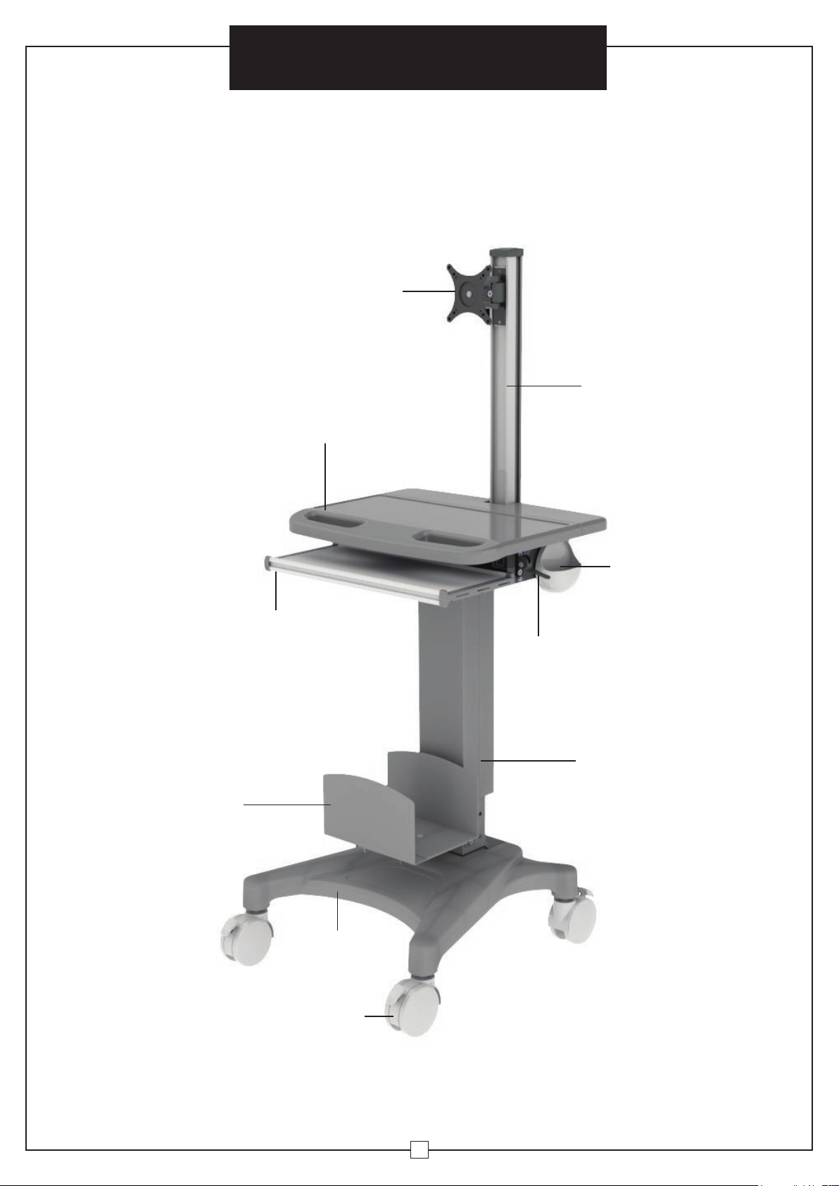
ET COMPOSANTS
Support d’écran VESA
avec ajustement par pivot
et inclinaison
Surface de travail avec poignées
Directives d’assemblage
Colonne
ACL avec
rangement
de câble
Plateau de clavier
dissimulé
Support
d’unité
centrale
Base
métallique
Support
de souris
Levier d’ajustement
vertical (Soulever le
levier pour ajuster)
Poteau de
soulèvement
Roulettes bloquantes
à pédale
24
Page 2

Distribucion Industrial Globales S DE RL DE CF
Assembly Instructions Instrucciones de Ensamblaje Directives d’assemblage
Customer Service
US: 1-800-645-2986
Mobile Sit and Stand Workstation
WARNING
IMPACT HAZARD!
Moving parts can crush and cut. Raise work surface before
removing the monitor. Failure to heed this warning may result
in serious personal injury or property damage!
Servicio de atención al Cliente
México: 01.800.681.6940
Model 695436
Service à la clientèle
Canada: 888-645-2986
WARNING
TIPPING HAZARD!
For carts without an internal
power system, a CPU should
be mounted to the cart before
displays are mounted. DO NOT
remove CPU while displays are
mounted because personal injury
or equipment damage may occur.
WARNING
TO MOVE CART:
1. Lower the display to the
lowest position.
2. Disconnect any power cords.
3. Stow cords to keep out of the way.
4. Unlock casters and pivot to the
direction of travel.
5. Push the cart from the sides
using the hand holds.
WARNING
This component is under high tension, and can cause injury
or damage if release bolt Is removed before assembly. This
release bolt should only be removed after assembly is
complete. Please refer to manual.
EXCLUSIVE DISTRIBUTORS
globalindustrial.ca
1
012016
Page 3

Mobile Sit and Stand Workstation
Assembly Instructions
WARNING
This warning alerts you to the possibilities of serious injury
or death if you do not follow the following instructions. It is
the installer's responsibility to make sure all components
are properly assembled and installed using the instructions
provided. Severe personal injury and property damage can
result from improper installation or assembly.
WARNING
It is the installer's responsibility to make sure the combined
weight of all components does not exceed weight capacity
of 50Kg (110 lbs). Exceeding weight capacities can result in
severe personal injury or damage to equipment.
WARNING
WARNING
Attachment holes may be damaged if a powered screwdriver
is used to insert button head cap screws. Screws should first
be inserted and turned by hand with hexagon key or with
screwdriver before using a powered screwdriver to complete
the attachment.
Read the following warning before installing:
• Verify all parts are included. Do not install if the products or hardware are damaged.
• This product contains moving parts. Assemble with caution.
• This product contains small items. Keep these items away from children.
• Do not exceed the maximum weight capacity for this product. Exceeding the weight capacity
can result in serious personal injury or damage to equipment. Maximum weight capacity is
9kg (19.8 lbs.) for the monitor bracket, and 50kg (110 lbs.) for the work surface platform.
CONTENTS
1 2 3
Do not load mobile workstation above maximum weight
capacities.
Do not mount a display above recommended monitor sizes.
Do not allow children to climb on top of mobile
workstation.
Do not move mobile computer cart on sloping surface.
LCD Column
Qty. (1)
4
Keyboard Tray Slot Qty. (1)
7
VESA Bracket Qty. (1)
10 12 13
Round Head Hex Screw
M6 x 15mm Qty. (12)
14 16 17
Flat Head Hex Screw
M6 x 15mm Qty. (3)
11
Washer Qty. (4)
15
Phillips Screw M4 x 12mm Qty. (4)
Lift Pole
Qty. (1)
5
Work Surface Qty. (1)
8 9
Fixed Plate Qty. (1)
Round Head Hex Screw
M5 x 10mm Qty. (2) Phillips Screw M6 x 12mm Qty. (4)
Phillips Screw M4 x 25mm Qty. (4) Oval Spacers Qty. (4)
Base Qty. (1)
6
Mouse Holder Qty. (1)
CPU Holder and Screws Qty. (1)
22
18
19
Hex Allen Wrench 4mm Qty. (1) Hex Allen Wrench 5mm Qty. (1)Hex Allen Wrench 3mm Qty. (1)
20 21
Hex Allen Wrench 6mm Qty. (1)
2
Magnetic Screwdriver
Page 4

Directives d’assemblage
Chariot informatique mobile
à station assise ou debout
Spécifications
• Modèle: 695436
• Plage d’ajustement de la hauteur de l’ACL et de la surface de travail: 400 mm (16 po)
• Hauteur de la surface de travail: 892 à 1292 mm (35 à 51 po)
• Dimensions de la surface de travail: 560 (long) x 430 mm (lar) (22 x 17 po)
• Dimensions du plateau du clavier: 450 (long) x 200 mm (lar) (18 x 8 po)
• Le support ACL peut s’ajuster par inclinaison: ±90°, pivotement: ±15°
• Capacité de poids : jusqu’à: 9 kg (19,8 lb.); Appliqué à un écran ACL de ≤24 pouces
• Roulettes bloquantes à pédale: 101 mm (4 po) de diamètre
23
Page 5

Chariot informatique mobile
à station assise ou debout
Directives d’assemblage
Ajustement de
la résistance
13.
L’écran peut pivoter
horizontalement d’un côté à
l’autre, jusqu’à 15 degrés, comme
il est montré. Pour ajuster,
desserrez la vis bouton située
sur le joint du support VESA en
utilisant la clé hexagonale 4 mm
(19) fournie, puis resserrez à la
position désirée.
14. On peut également ajuster
l’inclinaison verticale de l’écran.
Pour ajuster, desserrez la vis
bouton située sur le joint du
support VESA en utilisant la clé
hexagonale 4 mm (21) fournie,
puis resserrez en position.
+15°
19
Réglage
du pivot de
l’écran
-15°
Réglage de
l’inclinaison
verticale de
l’écran
21
22
Page 6
Installation
Assembly Instructions
Mobile Sit and Stand Workstation
Attaching the Lift Pole
Note: This step may require
assistance. 1. Do not remove the gas
spring tension screw below the label
before completing the assembly. Put
lift pole (2) on the base (3). Note:
Back label must face back of base.
Install four round head hex screws
M6 x15mm (10) each with a washer
(11) through mounting holes in the
base and into lift pole with a 6mm
allen wrench (21) so the lift pole is
firmly attached.
Attaching Keyboard
Tray Slot
2. Put keyboard tray slot (4) on the
lift pole. Install four round head
hex screws M6 x15mm (10) through
mounting holes on the keyboard tray
slot and finally into lift pole with a
6mm allen wrench (21) so that the
keyboard tray slot is firmly attached to
the lift pole. No washers are required
for this portion of the installation.
2
Labels
should
face the
same side
3
21
10
11
10
Bottom of Base
4
Lever Installation
3. CAUTION! Do not remove the gas spring tension retainer
before assembling the lever. Put the lever through the hole on
the side of keyboard tray slot (See Figure A). Turn the lever by
facing up (See Figure B). Once the lever is in position, tighten
A B
Mouse Holder
Installation
4. Insert mouse holder (6) on
the side of keyboard tray slot
from top to bottom.
6
two round head hex screws M5 x10mm (12) with a 4mm allen
wrench (19), so that the lever is firmly secured to the keyboard
tray slot (Figure C).
1912
Lever
C
3
Page 7
Mobile Sit and Stand Workstation
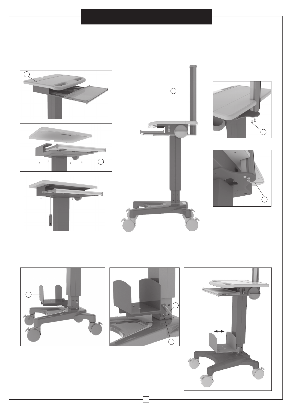
Attaching Work Surface Attaching LCD Column
5. Put the work surface (5) over the keyboard
tray slot. Install four phillips screws M6 x 12mm
(13) through mounting holes on the keyboard tray
slot and finally into work surface using long shaft
phillips magnetic screwdriver (22) until it is firmly
attached to keyboard tray slot.
5
Extend tray when
mounting work surface.
6. Put the LCD column (1) on the end of keyboard tray slot. Install three flat head hex
screws M6 x 15mm (14) through mounting holes on the keyboard tray slot and tighten
into LCD column with a 4mm allen wrench (19) until the LCD column is firmly attached
to keyboard tray slot.
1
Assembly Instructions
14
13
7. The CPU holder can be installed in front of or behind the fixed
column portion of the lift pole. To install, align the CPU holder
screw holes with the screw insert holes on the side of column,
9
19
then insert four round head hex screws M6 x 15mm (10) and
tighten using a 6mm allen wrench (21). The CPU holder width can
also be adjusted using the phillips screw driver.
21
10
4
Page 8

Chariot informatique mobile
à station assise ou debout
Directives d’assemblage
Installation de l’écran
8.
Choisissez la profondeur des vis Phillips M4 x 12 mm (15) ou M4
x 25 mm (16) relative aux trous de montage à l’arrière de l’écran.
Placez le support VESA (7) à l’arrière de l’écran. Alignez les trous
de montage avec les insertions de vis. Une fois le support VESA en
position, serrez avec soin les quatre vis jusqu’à ce que le support
VESA soit fermement fixé à l’écran. Cessez immédiatement si
- AVERTISSEMENT - une unité centrale devrait être montée au chariot avant l’installation des écrans.
vous rencontrez une résistance, ce qui pourrait endommager le
moniteur. Si vous rencontrez une résistance avant que le montage
soit fermement maintenu, vous pourriez devoir utiliser des vis moins
profondes ou des espaceurs. Veuillez consulter le manuel d’utilisation
de votre moniteur. Remarque: des espaceurs ovales (17) pourraient
être utilisés pour les types d’écrans courbés.
Fixer un support d’écran et d’unité centrale
10. Enlevez le couvercle de la colonne ACL (1), et insérez un écran
avec support VESA à partir du haut de la colonne ACL.
11. Une fois l’assemblage de l’écran en position, serrez les vis à
chacune des extrémités du support VESA avec une clé hexagonale 3
mm (18) en sens horaire, puis remettez le couvercle en place, au haut
de la colonne ACL.
9. Placez une plaque fixe (8)
7
16 15
17
sur le support VESA.
8
Cover
1
Retirez la vis de
réglage de la tension
du ressort à gaz.
Toutes les
étiquettes
doivent être du
même côté de
l’étiquette
de la base.
18
12. Après l’assemblage final, retirez les vis de réglage de la tension du
ressort à gaz, comme il est indiqué à la fig. (A) et (B) ci-dessous. Tirez le
levier vers le haut pour modifier la hauteur de la surface de travail.
Base mobile
Retirez la vis
de réglage de
la tension du
ressort à gaz.
B A
Sous la surface de travail
21
Page 9

Chariot informatique mobile
à station assise ou debout
Fixation à la surface de travail Fixer la colonne ACL
5. Placez la surface de travail (5) par-dessus la fente
du plateau du clavier. Installez quatre vis Phillips M6
x 12 mm (13) dans les trous de montage de la fente
du plateau du clavier et enfin, dans la surface de
travail en utilisant un Phillips tournevis magnétique
(22) jusqu’à ce que ce soit fermement fixé à la fente
du plateau du clavier.
5
Déployez le plateau lors du
montage de la surface de travail.
6. Placez la colonne ACL (1) sur l’extrémité de la fente du plateau du clavier. Installez
trois vis de montage M6 x 15 mm (14) dans les trous de montage de la fente du plateau
du clavier et serrez à travers la colonne ACL grâce à une clé hexagonale 4 mm (19),
jusqu’à ce que la colonne ACL soit fermement fixée à la fente du plateau du clavier.
1
Directives d’assemblage
14
13
7.
L’unité centrale peut être installée à l’avant ou à l’arrière de la
portion fixe de la colonne du poteau de soulèvement. Pour installer,
alignez les trous des vis du support de l’unité centrale au côté de la
9
19
colonne, puis insérez quatre vis bouton M6 x 15 mm (10) et serrez en
utilisant une clé hexagonale 6 mm (21). Le support de l’unité centrale
peut aussi être ajusté en utilisant un tournevis Phillips.
21
20
10
Page 10

Assembly Instructions
Mobile Sit and Stand Workstation
Display Installation - WARNING! A CPU should be mounted to the cart before displays are mounted.
9. Select the depth of the phillips screws M4 x 12mm (15)
or M4 x 25mm (16) relative to mounting holes in the back of
display. Place the VESA bracket (7) on the back of display.
Align the mounting holes with the screw inserts. Once the
VESA bracket is in position, carefully tighten the four screws
until the VESA bracket is firmly attached to display monitor.
Stop immediately if you encounter any resistance, or you
may damage your monitor. If you encounter resistance
before the mount is firmly attached, you may need to use
a shallower depth screw or spacers. Please consult your
monitor's operation manual. Note: oval spacers (17) may be
used for curved or other type of display monitors.
8. Put fixed plate (8) onto
7
16 15
17
VESA bracket.
8
Attaching Display
10. Take off the cover of LCD column (1), and insert display monitor
with VESA bracket from top down into the LCD column.
Cover
1
Remove gas spring
tension retaining
screw
All labels must
be on the same
side as the label
at the base.
12. After final assembly, remove the gas spring tension
retaining screws as shown in Fig. (A) and (B) below. Pull the
lever up to change the work surface to desired height.
11. Once the display assembly is in position, tighten screws at both
ends of VESA bracket with 3mm allen wrench (18) clockwise and put
the cover back on the top of LCD column.
18
Mobile Base
Remove gas
spring tension
retaining
screw
B A
Under Work Surface
5
Page 11

Mobile Sit and Stand Workstation
Assembly Instructions
Adjusting
Resistance
13. The monitor display can
horizontally swivel from side
to side up to 15 degrees as
shown. To adjust, loosen the
tension hex socket cap screw
located on the VESA bracket
Joint using the supplied 4mm
allen wrench (19) and then
tighten to desired position.
14. The monitor display can also
adjust for vertical tilt. To adjust,
loosen the tension hex socket
cap screw located on the VESA
bracket joint using the supplied
6mm allen wrench (21), and then
tighten to position.
+15°
19
Monitor
Swivel
Adjustment
-15°
Monitor
Vertical
Tilt
Adjustment
21
6
Page 12

Installation
Directives d’assemblage
Chariot informatique mobile
à station assise ou debout
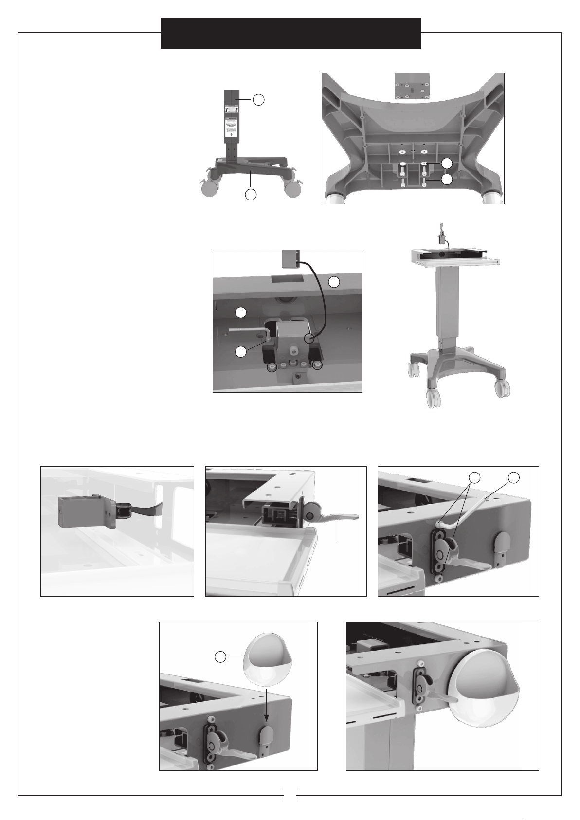
Fixation du poteau
de soulèvement
Remarque: Cette étape pourrait exiger
de l’aide. 1. Ne retirez pas la vis de
réglage de la tension du ressort à gaz sous
l’étiquette avant la fin de l’assemblage.
Placez le poteau de soulèvement (2) sur la
base (3). Remarque: l'étiquette de Retour
doit faire face arrière de la base . Installez
quatre vis bouton M6 x 15 mm (10) avec
une rondelle (11) en plaçant les trous dans
la base et dans le poteau de soulèvement
à l’aide d’une clé hexagonale de 6 mm (21)
afin que le poteau de soulèvement soit
fermement fixé.
Fixer la fente du
plateau du clavier
2. Placez la fente du plateau du clavier
(4) sur le poteau de soulèvement.
Installez quatre vis bouton M6 x 15
mm (10) dans les trous de montage
de la fente du plateau du clavier et
ensuite au poteau de soulèvement à
l’aide d’une clé hexagonale (21) afin
que la fente du plateau du clavier
soit fermement fixée au poteau
de soulèvement. Aucune rondelle
n’est requise pour cette portion de
l’installation.
2
Les étiquettes
devraient être
orientées du
même côté
3
21
10
11
10
Bas de la base
4
Lever Installation
3. ATTENTION! Ne retirez pas la bague d’arrêt de la tension
du ressort à gaz avant l’assemblage du levier. Placez le levier
dans le trou latéral de la fente du plateau du clavier (voir la
figure A). Tournez le levier en le redressant (voir la figure B).
A B
Installation du
support de souris
4. Insérez le support de souris
(6) sur le côté de la fente du
plateau du clavier, du haut
vers le bas.
6
Une fois le levier en position, serrez deux vis bouton M5 x
10 mm (12) avec une clé hexagonale 4 mm (19), afin que le
levier soit maintenu fermement à la fente du plateau du clavier
(figure C).
1912
Lever
C
19
Page 13

Chariot informatique mobile
à station assise ou debout
Directives d’assemblage
AVERTISSEMENT
Ces avertissements vous préviennent de la possibilité de blessures
graves ou de mort si vous ne respectez pas les directives suivantes
Il est de la responsabilité de l’installateur de s’assurer que tous
les composants sont correctement assemblés et installés selon
les directives fournies. Des blessures graves et dommages à la
propriété peuvent survenir d’une installation incorrecte ou d’un
mauvais assemblage.
:
AVERTISSEMENT
Les trous de fixation peuvent être endommagés si un tournevis
électrique est utilisé pour insérer les vis bouton. Les vis devraient
d’abord être insérées et tournées à la main avec une clé hexagonale
ou un tournevis avant d’utiliser un tournevis électrique afin de
compléter la fixation.
Il est de la responsabilité de l’installateur de s’assurer que le poids
combiné de tous les composants n’excède pas la capacité totale de
50 kg (110 lb). Le dépassement de la capacité de poids peut causer de
graves blessures ou endommager l’équipement.
Ne pas dépasser la capacité de poids du chariot informatique mobile.
Ne pas monter d’écran dépassant les tailles maximales recommandées.
Ne pas laisser les enfants monter sur le chariot informatique mobile.
Ne pas déplacer le chariot informatique mobile sur une surface en pente.
AVERTISSEMENT
AVERTISSEMENT
Lire l’avertissement suivant avant d’installer:
• Vérifiez que toutes les pièces sont incluses. Ne pas installer si les produits ou le matériel sont endommagés.
• Ce produit comporte des pièces mobiles. Assemblez avec précaution.
• Ce produit contient de petits éléments. Gardez hors de la portée des enfants.
• Ne pas dépasser la capacité maximale de poids de ce produit. Excéder la capacité de poids pourrait causer
des blessures corporelles ou endommager l’équipement. La capacité maximale est de 9 kg (19,8 lb) pour le
support du moniteur, et de 50 kg (110 lb) pour la plateforme de la surface de travail.
CONTENU
1 2 3
Poteau de
Colonne ACL
Qté (1)
4
Fente du plateau du clavier Qté (1)
7
Support VESA Qté (1)
10 12 13
Vis bouton M6 x 15 mm
Qté (12)
14 16 17
11
Rondelle
15
soulèvement
Qté (1)
5
Surface de travail Qté (1)
8 9
Plaque fixe Qté (1)
Qté (4)
Vis bouton M6 x 15 mm
Qté (2) Vis Phillips M6 x 12 mm Qté (4)
Base Qté (1)
6
Support de souris Qté (1)
Vis et support de l’unité centrale Qté (1)
22
Vis d’assemblage
M6 x 15mm Qté (3)
18
Vis Phillips M4 x 12mm Qté (4)
19
Clé hexagonale de 4mm Qté (1) Clé hexagonale de 5mm Qté (1)Clé hexagonale de 3mm Qté (1)
Vis Phillips M4 x 25mm Qté (4) Espaceurs ovales Qté (4)
20 21
Clé hexagonale de 6mm Qté (1)
18
Tournevis magnétique
Page 14

Mobile Sit and Stand Workstation
Specifications
• Model: 695436
• Height adjustment range for LCD and work surface: 400mm (16")
• Work surface height: 892mm-1292mm (35"- 51")
• Work surface dimensions: 560mm (L) x 430mm ( W) (22" x 17")
• Keyboard tray dimensions: 450mm (L) x 200mm (W) (18" x 8")
• LCD hanger can tilt adjustment: ±90°,swivel: ±15°
• Weight capacity: up to: 9kg (19.8 lbs.); Applied for ≤24 inch LCD display
• Pedal locking casters: 101mm (4") diameter
Assembly Instructions
7
Page 15

Mobile Sit and Stand Workstation
FEATURES AND
COMPONENTS
VESA monitor mount with
swivel and tilt adjustment
Work surface with handles
Assembly Instructions
LCD column
with cable
management
Hideaway keyboard tray
CPU holder
Metal base
Mouse
holder
Vertical
adjustment lever
(lift lever to adjust)
Lift pole
Pedal locking casters
8
Page 16

Distribucion Industrial Globales S DE RL DE CF
Assembly Instructions Instrucciones de Ensamblaje Directives d’assemblage
Customer Service
US: 1-800-645-2986
Servicio de atención al Cliente
México: 01.800.681.6940
Service à la clientèle
Canada: 888-645-2986
Chariot informatique mobile à station assise ou debout
Modèle 695436
AVERTISSEMENT
DANGER D’IMPACT!
Les pièces mobiles peuvent écraser et couper. Soulevez la
surface de travail avant de retirer le moniteur. Ne pas tenir
compte de cet avertissement pourrait causer de sérieuses
blessures corporelles ou des dommages à la propriété!
AVERTISSEMENT
DANGER DE RENVERSEMENT!
Pour les chariots sans système
d’alimentation interne, une unité
centrale devrait être montée au
chariot avant l’installation des
écrans. NE PAS retirer l’unité
centrale pendant que les écrans
sont montés en raison de
possibles blessures corporelles
ou dommages à l’équipement.
AVERTISSEMENT
POUR DÉPLACER LE CHARIOT:
1. Abaissez l’écran à la position la plus basse.
2. Débranchez tous les cordons d’alimentation.
3. Mettre les cordons en sécurité, hors
du chemin.
4. Débloquez les roulettes et faites pivoter dans
la direction du déplacement.
5. Poussez le chariot par les côtés en utilisant
les poignées.
AVERTISSEMENT
Poussez le chariot par les côtés en utilisant les poignées. Si
le composant est sous haute tension pouvant causer des
blessures ou dommages si le boulon de dégagement est
retiré avant l’assemblage. Ce boulon de dégagement ne
devrait être retiré qu’une fois l’assemblage terminé. Veuillez
vous référer au manuel.
distributeurs exclusifs
globalindustrial.ca
17
Page 17

Estación de trabajo
móvil para computadora
CARACTERÍSTICAS
Y COMPONENTES
Montaje de monitor
VESA con giro y ajuste
de inclinación
Superficie de trabajo con asas
Instrucciones de Ensamblaje
Columna LCD
con gestión
de cables
Bandeja del teclado
que se oculta
Soporte
de la CPU
Base de metal
Soporte
de ratón
Palanca de ajuste
vertical (Levante la
palanca para ajustar)
Barra de la
elevación
Ruedas de bloqueo
del pedal
16
Page 18

Distribucion Industrial Globales S DE RL DE CF
Assembly Instructions Instrucciones de Ensamblaje Directives d’assemblage
Customer Service
US: 1-800-645-2986
Estación de trabajo móvil para computadora
ADVERTENCIA
¡IMPACTO DE PELIGRO!
Las partes móviles pueden aplastar y cortar. Levante
superficie de trabajo antes De retirar el monitor. ¡No prestar
atención a esta advertencia puede resultar en lesiones
personales graves o daños materiales!
ADVERTENCIA
¡PELIGRO DE VUELCO!
Para los carros sin un sistema
de alimentación interna, la CPU
debe montarse en el carro
antes de montar las pantallas.
NO retire la CPU mientras se
montan pantallas porque pueden
producirse lesiones personales o
daños en el equipo.
Servicio de atención al Cliente
México: 01.800.681.6940
Modelo 695436
Service à la clientèle
Canada: 888-645-2986
ADVERTENCIA
PARA MOVER EL CARRO:
1. Baje la pantalla hasta la posición
más baja.
2. Desconecte todos los cables de
alimentación.
3. Recoja los cables para mantenerlos
fuera del camino.
4. Quite el seguro de las ruedas y gire
en la dirección de desplazamiento.
5. Empuje el carro de los lados
utilizando las manijas.
ADVERTENCIA
Este componente está bajo alta tensión, y puede causar
lesiones o daños si el el perno de liberación se retira
antes del montaje. Este perno de liberación sólo debe
ser retirado después de completar el montaje. Por favor,
consulte el manual.
DISTRIBUIDORES EXCLUSIVOS
globalindustrial.ca
9
Page 19

Estación de trabajo
móvil para computadora
Instrucciones de Ensamblaje
ADVERTENCIA
Esta advertencia le alerta sobre la posibilidad de lesiones
graves o la muerte si no se siguen las instrucciones siguientes.
Es responsabilidad del instalador asegurarse de que todos los
componentes estén correctamente montados e instalados
usando las instrucciones proporcionadas. Lesiones y daños
graves a la propiedad personal pueden ser el resultado de la
instalación o montaje incorrecto.
ADVERTENCIA
Es responsabilidad del instalador asegurarse de que el peso
combinado de todos los componentes no exceda la capacidad
de peso de 50Kg (110 lbs). Exceder capacidades de peso
puede resultar en lesiones corporales graves o daños al equipo.
ADVERTENCIA
ADVERTENCIA
Los Orificios de fijación pueden dañarse si se usa
un destornillador eléctrico para insertar los tornillos. Los
tornillos deben ser insertados y apretados n a mano con
llave hexagonal o con un destornillador antes de utilizar un
destornillador eléctrico para finalizar la unión.
Lea la siguiente advertencia antes de instalar:
• Verifique que todas las partes estén incluidas. No instale si los productos o el equipo están dañados.
• Este producto contiene piezas móviles. Ensamble con precaución.
• Este producto contiene piezas pequeñas. Mantenga estos artículos lejos de los niños.
• No exceda la capacidad máxima de peso de este producto. Exceder la capacidad de peso puede resultar
en lesiones personales graves o daños al equipo. La capacidad máxima de peso es 9kg (19,8 lbs.) Para el
soporte del monitor, y 50 kg (110 lbs.) Para la plataforma de la superficie de trabajo.
No cargue el carrito móvil de computadora por encima
de las capacidades máximas de peso.
No monte una pantalla por encima de tamaños de
monitor recomendados.
No permita que los niños se suban en la parte superior
del carro móvil de computadora.
No mueva el carro móvil de computadora en una
superficie inclinada.
CONTENIDO
1 2 3
Barra de
Columna LCD
Cant. (1)
4
Bandeja del teclado Cant. (1)
7
Soporte VESA Cant. (1)
10 12 13
Tornillo Cabeza Redonda
hexagonal M6 x 15mm Cant. (1)
14 16 17
11
Arandela
15
elevación
Cant. (1)
5
Superficie de trabajo Cant. (1)
8 9
Placa fija Cant. (1)
Cant. (1)
Tornillo Cabeza Redonda hexagonal
M5 x 10mm Cant. (1)
Base Cant. (1)
6
Soporte del ratón Cant. (1)
Soporte de CPU y tornillos Cant. (1)
22
Tornillo Phillips M6 x 12mm
Cant. (1)
Tornillo Cabeza plana hexagonal
M6 x 15mm Cant. (1)
18
Llave Allen hexagonal de 3mm
Cant. (1)
Tornillo Phillips M4 x 12mm Cant. (1)
Tornillo Phillips M4 x 25mm Cant. (1)
19
Llave Allen hexagonal de 4mm
Cant. (1)
20 21
Llave Allen hexagonal de 5mm
Cant. (1)
10
Espaciadores Ovales Cant. (1)
Llave Allen hexagonal de 6mm
Cant. (1)
Destornillador magnético
Page 20

Instrucciones de Ensamblaje
Estación de trabajo
móvil para computadora
Especificaciones
• Modelo: 695436
• Rango de ajuste de altura para el LCD y la superficie de trabajo: 400mm (16")
• Altura de la superficie de trabajo: 892mm-1292mm (35 "- 51")
• Dimensiones de la superficie de trabajo: 560mm (L) x 430mm (A) (22" x 17")
• Dimensiones de la bandeja del teclado: 450mm (L) x 200mm (A) (18 " x 8")
• Soporte de LCD se puede inclinar con ajuste: ± 90 °, giro: ± 15 °
• Capacidad de peso: hasta: 9 kg (19.8 lbs.); Aplicado para ≤24 pulgadas monitor LCD
• Ruedas de bloqueo del pedal: 101 mm (4") de diámetro
15
Page 21

Estación de trabajo
móvil para computadora
Instrucciones de Ensamblaje
Ajuste de
Resistencia
13.
La pantalla del monitor
se puede girar sobre un eje
horizontal de lado a lado hasta
15 grados, como se muestra.
Para ajustar, afloje el tornillo de
cabeza hexagonal de tensión que
se encuentra en el soporte VESA
utilizando la llave Allen de 4 mm
suministrada (19) y apriete a la
posición deseada.
14. La pantalla del monitor
también puede ajustar la
inclinación vertical. Para ajustar,
afloje el tornillo de tensión de
cabeza hexagonal situado en la
articulación del soporte VESA con
la llave allen de 6 mm suministrada
(21) y apriete a la posición.
+15°
19
Ajuste
Giratorio del
Monitor
-15°
Ajuste
vertical de la
inclinación
del monitor
21
14
Page 22

Instalación
Instrucciones de Ensamblaje
Estación de trabajo
móvil para computadora
Fijación del soporte
de elevación
Nota: Este paso puede requerir
asistencia. 1. No quite el tornillo de
tensión del resorte debajo de la etiqueta
antes de completar el montaje. Ponga
soporte de la elevación (2) en la base (3).
Nota: contraetiqueta debe enfrentar parte
de atrás de la base. Instale cuatro tornillos
hexagonales de cabeza redonda M6 x
15mm (10) cada uno con una arandela
(11) a través de los agujeros de montaje
en la base y en la barra de elevación con
una llave allen de 6mm (21) de forma que
la barra de elevación esté bien conectada.
Colocación de la
bandeja del teclado
2. Coloque la bandeja del teclado (4)
en la barra de elevación. Instale cuatro
tornillos hexagonales de cabeza
redonda M6x15mm (10) a través de
los agujeros de montaje en la ranura
de la bandeja del teclado y, finalmente,
en la barra de elevación con una llave
allen de 6mm (21) de manera que la
bandeja del teclado está firmemente
conectada a la barra de elevación. No
se requieren arandelas para esta parte
de la instalación.
2
Las etiquetas
de base deben
enfrentar el
mismo lado
3
21
10
11
10
Parte inferior de la base
4
Instalación de palanca
3. ¡CUIDADO! No quite el resorte de tensión antes de montar
la palanca. Ponga la palanca a través del agujero en el lado
de la ranura de la bandeja del teclado (Ver Figura A). Gire la
palanca hacia arriba (Ver Figura B). Una vez que la palanca
A B
Instalación del
soporte de ratón
4. Inserte el soporte de ratón
(6) en el lado de la ranura de la
bandeja del teclado de arriba
a abajo.
6
esté en posición, apriete los dos tornillos hexagonales de
cabeza redonda M5 X 10mm (12) con una llave Allen de 4 mm
(19), de modo que la palanca esté firmemente asegurada a la
ranura de la bandeja del teclado (Figura C).
1912
Palanca
C
11
Page 23

Estación de trabajo
móvil para computadora
Instrucciones de Ensamblaje
Fijación Superficie de trabajo
5. Ponga la superficie de trabajo (5) sobre la ranura de la
bandeja del teclado. Instale cuatro tornillos Phillips M6 x
12mm (13) a través de los agujeros de montaje en la ranura
de la bandeja del teclado y, finalmente, en la superficie
de trabajo utilizando destornillador Phillips destornillador
magnético (22) hasta que esté firmemente conectado a la
ranura de la bandeja del teclado.
5
Extienda la bandeja al
montar la superficie
de trabajo.
13
Fijación de Columna LCD
6. Ponga la columna del LCD (1) en el extremo de ranura de la bandeja de
teclado. Instale tres tornillos hexagonales de cabeza plana M6 x 15mm (14)
a través de los agujeros de montaje en la ranura de la bandeja del teclado
y apriete en la columna LCD con una llave allen de 4mm (19) hasta que la
columna de la LCD se une firmemente a la ranura de la bandeja del teclado.
1
14
7. El soporte de la CPU puede ser instalado por delante o por detrás
de la de columna fija de la barra elevadora. Para instalarlo, alinee
los orificios de los tornillos del soporte de la PU con los orificios de
inserción de tornillos en el lado de la columna, a continuación, inserte
9
19
cuatro tornillos hexagonales de cabeza redonda M6 x 15mm (10) y
apriete con una llave allen de 6 mm (21). El ancho del soporte de la
CPU también puede ajustarse con el destornillador Phillips.
21
12
10
Page 24

Estación de trabajo
móvil para computadora
Instrucciones de Ensamblaje
Instalación de Pantalla -
8. Seleccione la profundidad de los tornillos Phillips M4 x 12mm (15)
o M4 x 25mm (16) en relación con los agujeros de montaje en la parte
posterior de la pantalla. Coloque el soporte VESA (7) en la parte posterior
de la pantalla. Alinee los orificios de montaje con los insertos roscados.
Una vez que el soporte VESA está en posición, apriete con cuidado
los cuatro tornillos hasta que el soporte VESA está firmemente unido al
ADVERTENCIA - La CPU debe montarse en el carro antes de montar las pantallas.
monitor. Deténgase inmediatamente si encuentra alguna resistencia,
o puede dañar el monitor. Si se encuentra con la resistencia antes de
que el montaje esté bien conectado, es posible que tenga que utilizar
un tornillo a menor profundidad o espaciadores. Por favor consulte el
manual de operación de su monitor. Nota: los espaciadores ovales (17)
puede ser utilizados para monitores de visualización curvados u otros.
Colocación de Pantalla y Soporte para la CPU
10. Saque la cubierta de la columna de LCD (1), e inserte el monitor
con el soporte VESA, de arriba hacia abajo en la columna de la LCD.
9. Coloque la placa fija (8)
7
16 15
17
11. Una vez que el ensamblaje de la pantalla está en posición, apriete
los tornillos en ambos extremos del soporte VESA con una llave allen de
3 mm (18) en el sentido de las manecillas del reloj y ponga la tapa en la
parte superior de la columna de LCD.
sobre el soporte VESA.
8
Cover
1
Quite la tensión el
resorte del tornillo
de retención
Todas las
etiquetas
deben estar en
el mismo lado
que la etiqueta
en la base.
18
12. Después del montaje final, quite el resorte de retención de tornillos como se muestra en
la Fig. (A) y (B) a continuación. Tire de la palanca hacia arriba para cambiar la superficie de
trabajo a la altura deseada.
Base Móvil
Quite la tensión
el resorte del
tornillo de
retención
B A
Bajo la superficie de trabajo
13
 Loading...