

Page 1
Instruction Manual
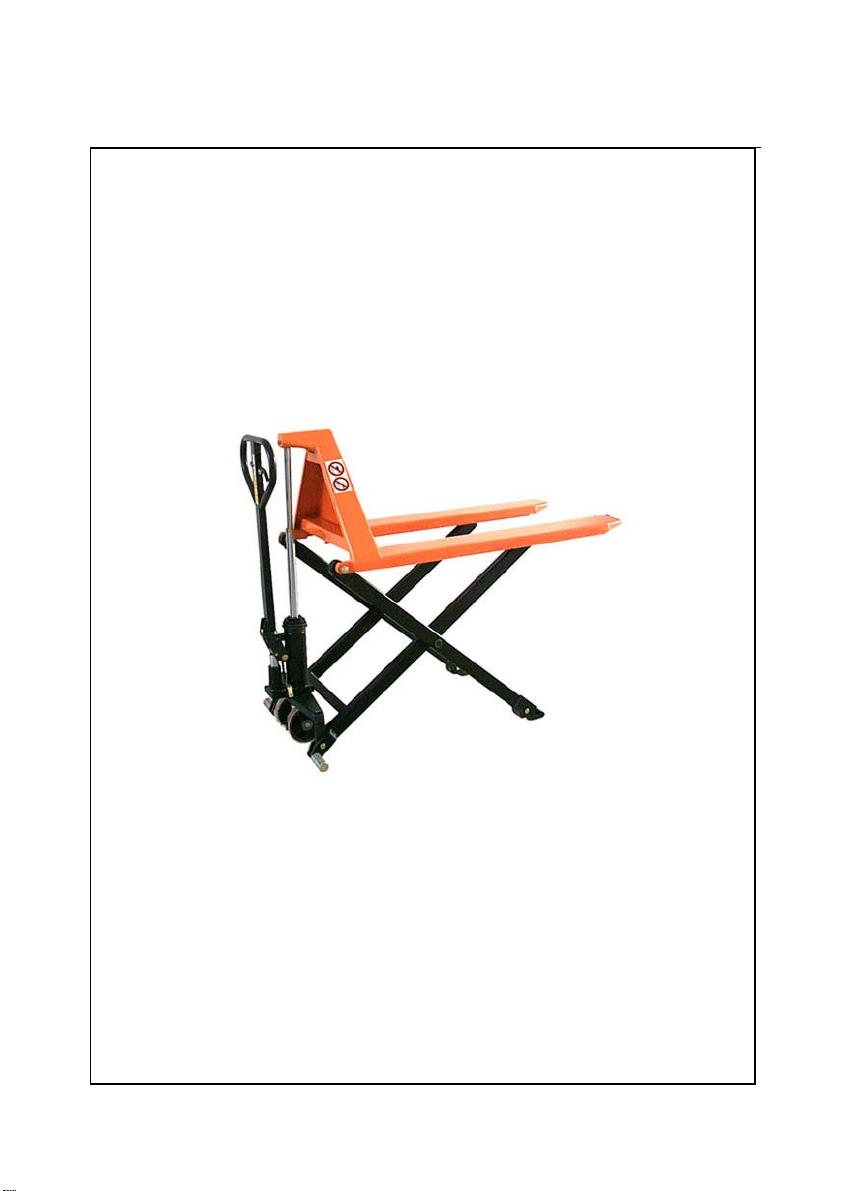
High Lift Hand Truck
Note: The Owner/Operator must read carefully and understand
all the information presented here before operation.
Page 2

CONTENT
1. Specification…………………………………………. 2
2. Safety Instructions…….…………………………….. 2
3. Installation & Adjustment…………………………… 3
3.1
Screw (part No.158)………….
………………
3.2 Handle………………………………………… 3
4. Trouble Shooting Guide………………………….…. 6
5. Exploded View & Part List………………………….. 7
5.1 Fork Exploded View ………………………… 7
5.2 Pump Assembly Exploded View……….…... 9
3
2
Page 3

THANK YOU FOR USING THIS HIGH LIFT HAND TRUCK. FOR
YOUR SAFETY AND CORRECT OPERATION, PLEASE CAREFULLY
READ THIS INSTRUCTION BEFORE USING IT.
NOTE: All of the information reported herein is based on data
available at the moment of printing. The factory reserves the right to
modify its own products at any moment without notice and incurring in
any sanction. So it is suggested to always verify possible updates.
1. SPECIFICATIONS
Model
Rated lifting capacity 1000 kgs 1500 kgs
Max. Fork height 800 mm 800 mm
Min. Fork height 85 ±2 mm 85 ±2 mm
Fork length 1140 mm 1100 mm
Fork width (outside) 520 mm 680 mm 520 mm 680 mm
Fork width (inside) 196 mm 356 mm 196 mm 356 mm
Lifting speed 9 mm/stroke
Descending speed ∠0.1 mm/second
N.W. 105 kgs 112 kgs 118 kgs 125 kgs
HSP1-520 HSP1-680 HSP11/2-520 HSP11/2-680
2. SAFETY INSTRUCTIONS
1. The truck shall be used in accordance with instructions handbook.
2. Don’t put the hand & foot under the fork at any time.
3. Don’t work on the slope surface.
4. Quick lifting is prohibited for loads of more than 300 kgs. Any
manipulation of the pressure relief valve is strictly prohibited. All
assembling, adjusting and maintenance shall only be done by
industrial mechanics trained people. These people must be familiar
with all safety regulations of European and national where the item is
in use relating to the operation and maintenance of pedestrian
controlled industrial trucks.
5. Load should be put on the fork center. Side-load is strictly prohibited.
6. The truck shall not be used to transport persons.
7. It is recommended to the driver to wear security shoes.
8. No modifications shall be carried out which adversely affect the
compliance of the truck with prEN 1757-4.
3
Page 4
3. INSTALLATION & ADJUSTMENT
1. Screw(part No.158)
● To prevent oil-leaking from oil tank during transportation, Air Screw
(part No.158) is replaced with Oil-sealing Screw in the factory. But it
has to be replaced back when you put this truck in use.
● How to change: Screw out Oil-sealing Screw, then screw in Air
Screw With which the Pump housing(No.160) is hung, thus keep oil
tank always connecting with atmosphere.
2. Handle
During transportation, the handle is disassembled from the truck and
packed separately. It has to be assembled back and adjusted
properly and carefully before use.
A Handle installation
● Take 3 pieces of M10 Nut (No.185) & Spring washer from spare parts
bag. Select handle to match the truck with the same fitting
numbers.
● Assemble the handle on the Handle Base (No.181) with 3 pieces of
M10 Nut & Spring Washer tightly.
● Put the chain’s Eye Bolt (No.110) in the slot at the front end of
Pendulum Arm (No.112).
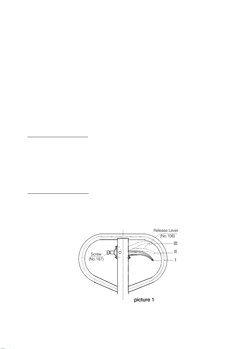
B Handle adjustment
● There are 3 different positions with different functions for the Release
Lever (part No.106). See picture 1
:
4
Page 5

Position I: Quick lifting for fork.
Position II: Slow lifting for fork.
Position III: Descending for fork.
● Test different functions by putting the Release
Lever in 3 different positions respectively.
If it does not function properly, then adjusting
Lock Nut (No.113) by following process. See picture 2
Problems Turning direction of Lock Nut
Fork not lifted up – (counter-clockwise)
Fork not lowering down + (clockwise)
Slow lifting no function + (clockwise)
Quick lifting no function – (counter-clockwise)
● Function of Adjusting Screw (No.187) for Release Lever (see
picture 1)
To fix release lever (No.106) into its 3 positions properly by adjusting
the screw, you can adjust the operating force of the release lever.
To prevent accidental touch of the Release Lever which could cause
sudden sliding down of the fork. You can tighten the Screw (No.187)
in the position I or II of the Release Lever (No.106).
See picture 1
● How to release the air from the pump.
5
Page 6

See picture 3
When pushing the handle down, the fork can’t be lifted instantly.
Please loosen the Screw (No.130) on the pump while pushing the
handle down slowly to release the air from the pump. Then tighten
the screw.
● When to add oil
See Picture 3
If the fork can’t be pumped up to its rated highest position, you may
have to add hydraulic oil into the oil tank. The hydraulic fluid to be
used must have a quality of ISO VG22 or equivalence. Mixing of
different fluids is prohibited!
6
Page 7

4.TROUBLE SHOOTING GUIDE
Items Symptom Possible cause Aliments
Fork can not be
1
pumped up
Fork can’t be
2
released down
Fork can’t be
pumped up to
3
rated highest
position.
Fork lifting
speed has no
difference
4
between
position I and
position II of
release lever.
1. Low oil level in oil
tank.
2. Exist air in the
hydraulic system.
3. Adjusting nut is not
adjusted properly.
1. Fork blocked.
2. Adjusting nut not
adjusted properly.
Oil is not enough.
Adjusting nut is not
adjusted properly.
1 .Add proper hydraulic
oil.
2. Fast operating the
handle for several
times. Bleed the
system.
3. Adjust adjusting nut.
(see picture 2)
1. Check and remove the
block.
2. Adjust adjusting nut
properly.
(see picture 2)
Add hydraulic oil.
(see picture 3)
Adjust adjusting nut.
(see picture 2)
7
Page 8

5. EXPLODED VIEW & PART LIST
5.1 Fork Exploded View & Part List
8
Page 9

No. Description Qty
1Fork 1
2Screw 1
3Nut 1
4Power Unit 1
5Hold Yoke 1
6 Wheel Yoke 1
7 Centrifugal Axle 2
8Spacer 2
9 Steering Wheel 2
10 Snap Ring 8
11 Pin 2
12 Snap Ring 12
13 Bush 2
14 Leg 2
15 Leg 1
16 Bush 2
17 Pin 2
18 Washer 2
19 Nut 2
20 Washer 8
21 Ball Bearing 8
22 Front Wheel 2
23 Wheel Axle 2
24 Roller 4
25 Bush 2
26 Washer 4
27 Spring Washer 2
28 Nut 2
31 Screw 1
32 Nut 1
30
Steering Wheel Assembly
(incls.6,9,10,21、31、32)
1
5.2 Pump Exploded View & Part List
9
Page 10

10
Page 11

Part No. DESCRIPTION QTY Part No. DESCRIPTION QTY
71 Washer 1 ※ 128 O-Ring 1
72 Spring 1 129 Release Indicator 1
73 Bush 2 ※ 130 Screw 1
74 Washer 1 131 Pump Piston 1
75 Gasket 1 132 Guide Ring 1
101 Locknut 1 133 Y-Ring 1
102 Handle 1 134 Washer 1
103 Screw 1 135 Snap Ring 1
104 Pin 1 136 Scraper Ring 2
105 Roller 1 137 O-Ring 2
106 Release Lever 1 138 Y-Ring 2
107 Release Rod 1 139 Pump Cylinder 1
108 Chain Connector 3 140 O-Ring 1
109 Chain 1 141 Spring 1
110 Eye Bolt 1 142 Hi-pressure Piston 1
※111 Washer 1 143 O-Ring 1
112 Pendulum Arm 1 144 Ball 1
113 Pendulum Arm Nut 1 145 Spring 1
114 Positioner 1 146 Adjusting Screw 1
115 Screw 5 147 Sealing Screw 1
116 Washer 2 148 Screw 1
117 Pin 1 149 Snap Ring 2
118 Valve Insert 1 150 O-Ring 2
119 Seat 1 153 O-Ring 1
120 Screw 2 155 O-Ring 1
121 Gasket 2 157 Screw 1
122 Spring 2 158 Air Screw 1
123 Release Valve 2 159 Cylinder 1
124 Ball 2 160 Pump Housing 1
125 Valve Insert 1 161 Thrust Bearing 1
126 O-Ring 8 162 Ball 1
127 Spring 1 163 Snap Ring 1
11
Page 12

Part No. DESCRIPTION QTY Part No. DESCRIPTION QTY
164 Washer 1 187 lock Screw For Release Lever 1
170 Bush 2 188 Spring Socket 1
171 Piston 1 189 Spacer 1
172 Screw 1 190 Copper Piston 1
173 Axle 1 191 Snap Ring 1
174 Gasket 1 192 Snap Ring 2
175 Lock Screw 1 193 Spring 1
176 Rubber Sleeve 1 194 Pin 1
177 Washer 1 195 Ball 1
178 Washer 5 301 Bush 1
180 Adjusting Screw 1 302 Back-Up ring 1
181 Handle Base 1 303 Y-Ring 1
182 Adjusting Washer 1 304 Bush 1
183 Rubber Sleeve 1 305 Snap Ring 1
184 Spring Guide 1 306 Piston Rod 1
185 Screw 3 307 Cylinder Head 1
186 Spring Washer 3 308 Lifting Ram 1
(incls.71,72,73,74,75,104,105,111,112,117,118,119,120,121,122,123,
124,125,126,127,128,129,130,131,132,133,134,135,136,137,138,139,
300
140,141,142,143,144,145,146,147,148,149,150,153,155,157,158,159,
160,163,164,170,171,172,173,174,175,176,177,180,181,182,183,184,
185,186,190,191,192,301,302,303,304,305,306,307,308)
50
(incls.101,102,103,106,107,108,109,110,113,114,115,116,178,187,188,1
89,193,194,195)
Remark: ※Parts with “ ” mark are supplied together with the High Lifter
and packed in the poly bags.
Pump unit
Handle assembly
* VERSION TWO
12
1
1
 Loading...