

Page 1
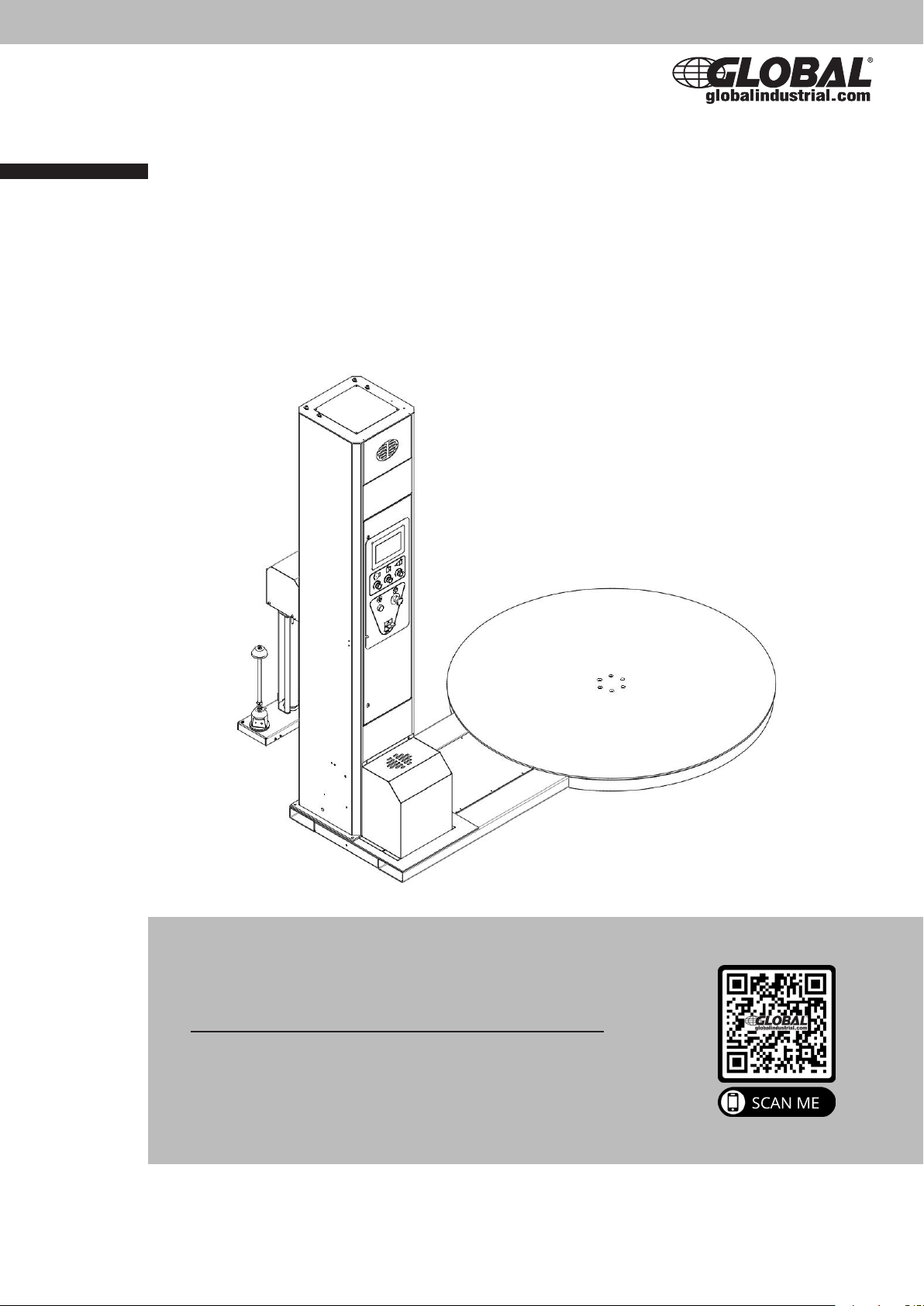
Semi-Auto Low Profile
Stretch Wrap Machine
User Manual
Model no. 412409
Globalindustrial.com
Customer Service
US: 1-800-645-2986
CA: 1-888-645-2986
OPTIONAL
Stretch Wrap Machine Ramp
Model no. 412410
Page 2
2
Table of Content
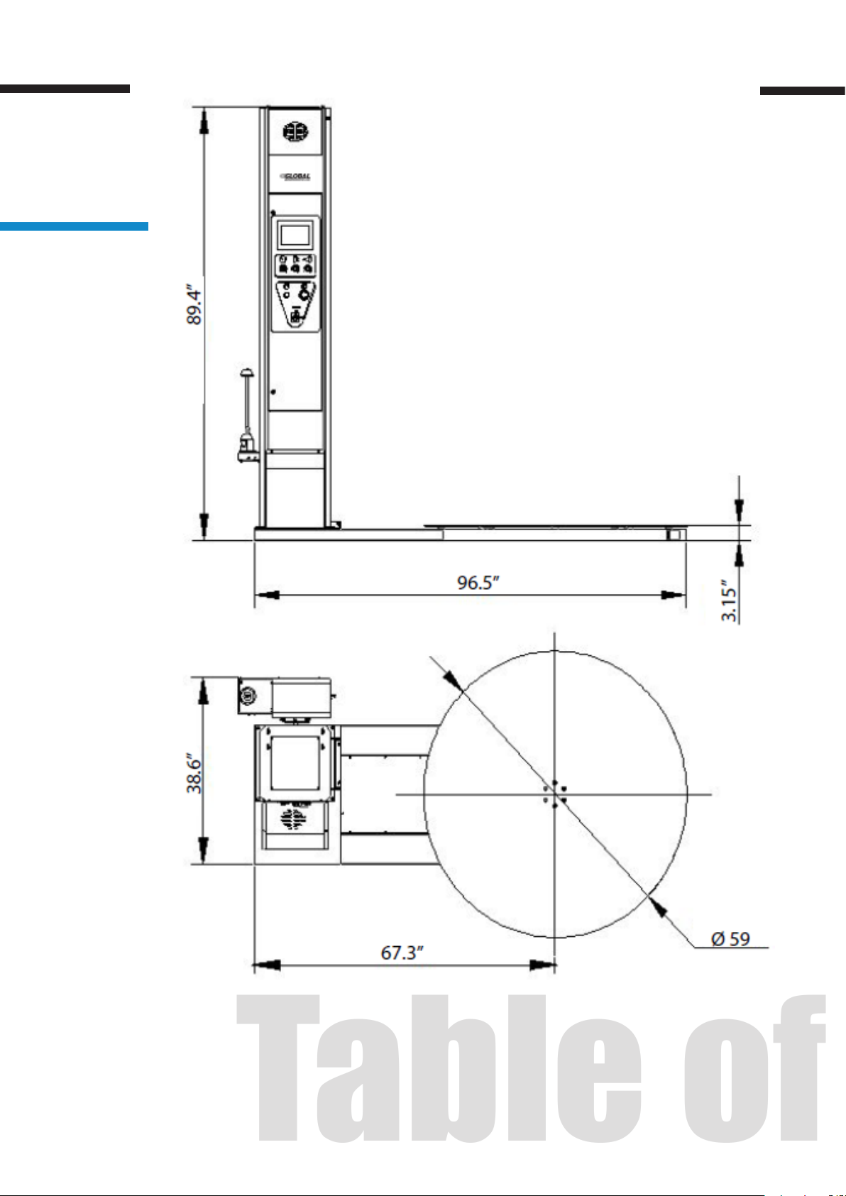
Machine Dimensions
Figure 1
Page 3

Table of Contents
3
1
2
3
4
System Specifications
System Set-up
2.1 Machine Set-up
2.2 Installation
Control Panel Buttons
Operator Controls
4.1 Manual
4.2 Auto
4.3 Input & Output (I/O)
4
6
7
8
10
12
12
13
14
5
6
4.4 Film Loading
4.5 Machine Operation
Maintenance & Troubleshooting
Components & Parts
14
16
18
20
Page 4
4
System Specication
1. System Specification
Machine Dimensions
(See Figure 1)
Length 96.5”
Width 59”
Height 89.4”
Turntable Diameter 59”
Turntable Height from Floor 3.15”
Wrapping Height 83”
Operation Space 97” x 60” x 90”
Maximum Load Size 52” x 52” x 82”
s
Table 1
Electrical Specications
• 110 VAC, 60 Hz, Single-phase, 9.1AMP
• Turntable motor: 550W
• Lift motor: 200W
• Pre-stretch Motor: 200W
Turntable System
• 13 RPM turntable maximum speed
• 4,400 lbs. turntable maximum load capacity
• 1-10 round/minute
• Clockwise rotating turntable direction
Film Delivery System
• Innite / Manual Stretch Adjustment
• 10” Diameter Roll Capacity
• 3” inner lm roll diameter
• 20” Roll Width Capacity
Page 5

Machine Features
• Programmable logic controller (PLC) user interface
• 6 modes: that’s 5 automatic modes + 1 manual mode.
• The lm carriage adopts close loop self-adjusting technology, to ensure each
package is evenly wrapped.
• Allowable package weight (22 lbs – 4400 lbs)
• SAFETY: The machine has an emergency stop button & sensor underneath the
lm carriage. Once an object is detected underneath the moving lm carriage, the
machine will stop.
CAUTION!
5
When servicing drive and controllers, there may be exposed components with
housings or protrusions at or above the line potential. Extreme care should be taken
to protect against shock.
The user is responsible for conforming to all applicable code requirements with
respect to grounding requirements. Do NOT use extension cords to operate the
equipment
Disconnect AC input power when the machine is not in use and before checking
components, performing maintenance, cleaning up, and. Do NOT connect or
disconnect wires and connectors while power is applied to the circuit.
Always plug into a grounded outlet with the rated voltage
110 V
WARNING!
Loose clothing must NOT be worn while the machine is in operation. Stay clear of
moving parts while the machine is running.
Page 6
6
System Set-up
2. System Set-up
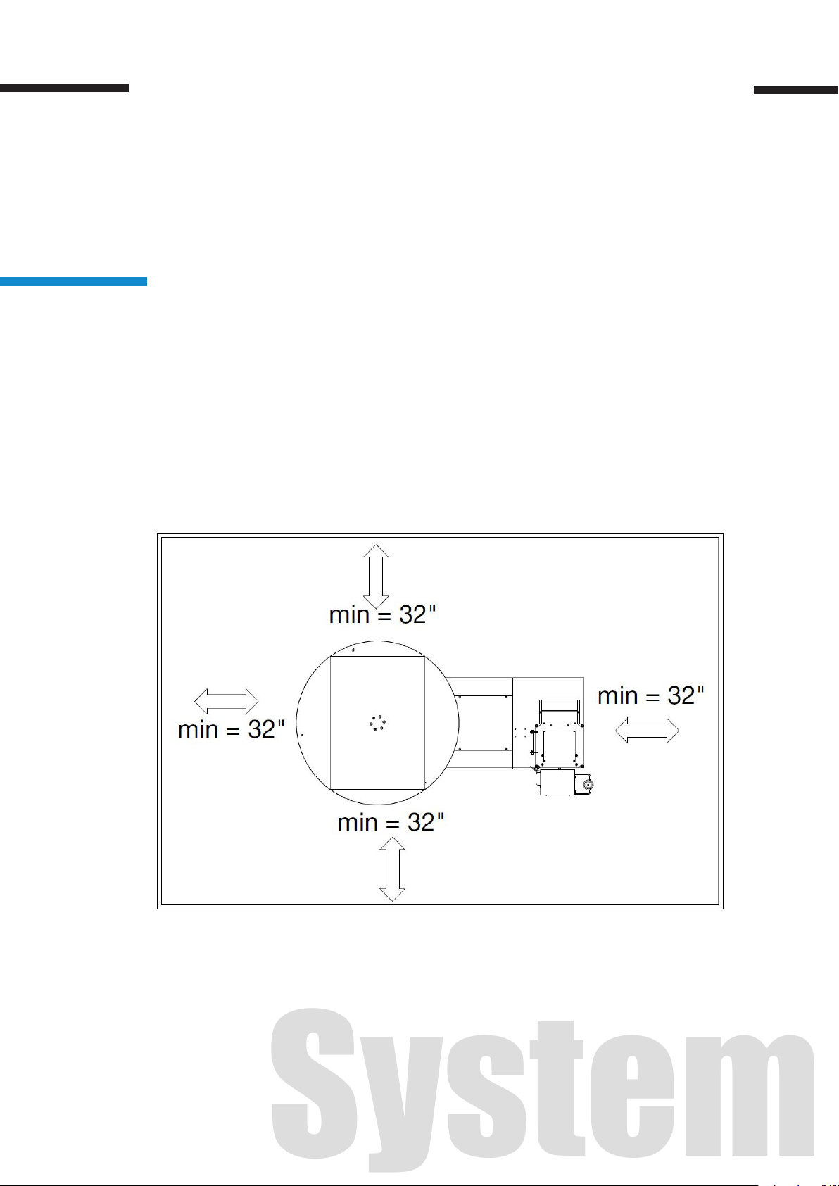
Machine Placement
Place the Semi-automatic Stretch Wrap Machine close to an area where you will
be wrapping your pallet loads. Refer to gure 2 t o insure the m achine meets the
minimum clearance space requirements. Make sure that there is sucient room to
load/unload the machine and that you do not stretch the wiring cable. Remember,
you will need to provide electrical service to a 110 VAC, 9.1-AMP outlet.
(See Figure 2)
Floor Weight Bearing Tolerance
The oor must be able to bear the weight of the machine, the weight of the maximum
load, plus a safety factor. The floor must also be able to tolerate the stress of the
machine operation. If the truck will operate on the same weight bearing area, add
the weight of the trucks to the weight bearing stress tolerance requirement.
Figure 2
Page 7
2.1 Machine Set-up
1. Place the crated machine close to the designated wrap area. Remove all shipping
fasteners holding the machine to the pallet. The machine may be crated with the tower
tilted down and the motor cover front carriage roller removed for shipping purpose.
2. Place forks of the forklift through the tubes provided at the rear base of the module,
remove the machine from the crate and place it at the designated wrap area.
3. Check all internal connections to ensure there is no loose/disconnected electrical
wiring,
4. Connect the motor wiring and sensor leads according to the corresponding wire
numbers.
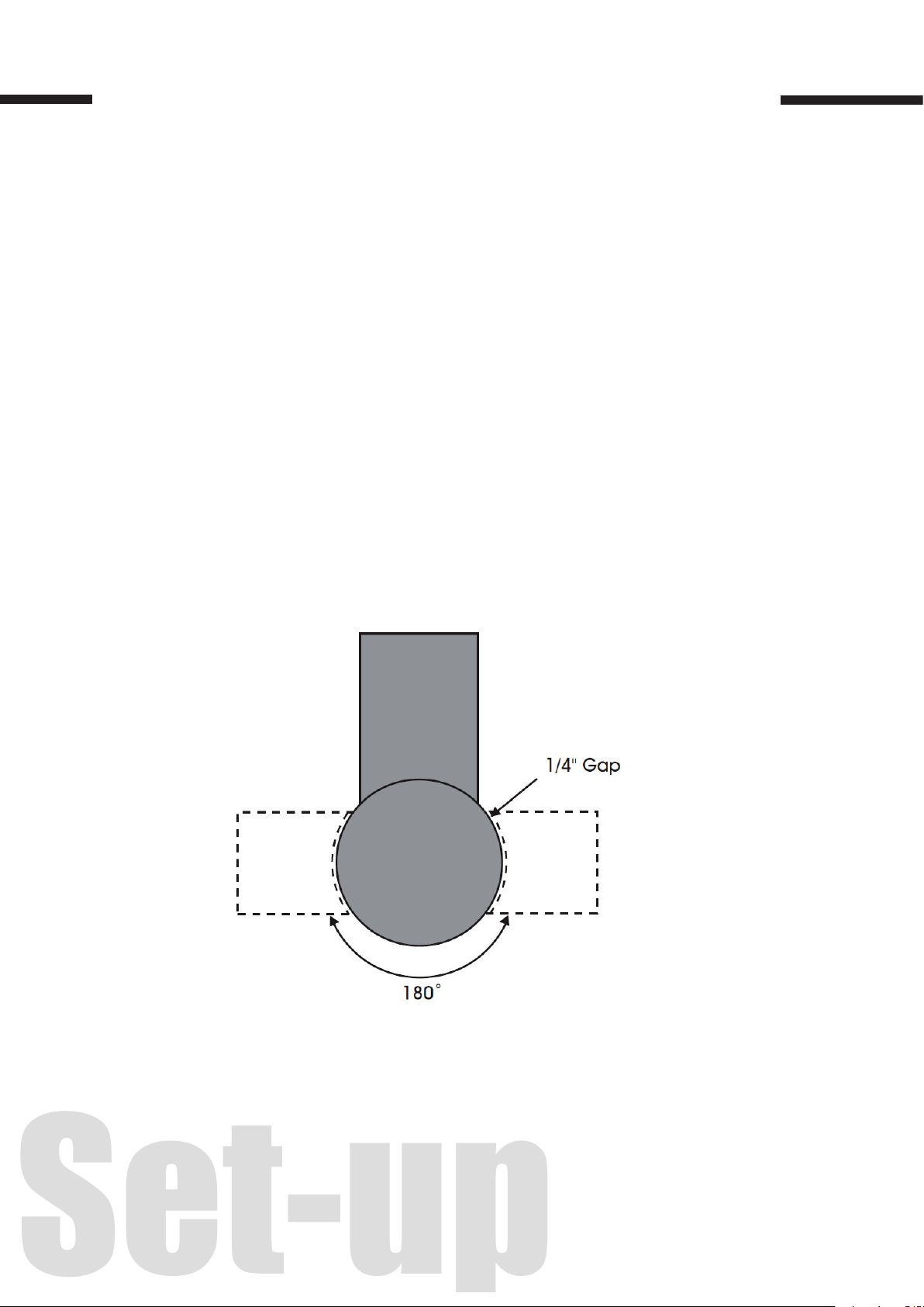
5. If the OPTIONAL ramp (Model no. 412410) is purchased: select a ramp position illus-
trated below. The ramp can be positioned anywhere in a 180 rotation around the front
of the turntable. There should be a ¼” gap between the turntable and the ramp. The
ramp should be fully supported by the oor. (See Figure 3)
7
Figure 3
Page 8
8
2.2 Installation
NOTE: Installation requires two people.
CAUTION
Be careful when standing on the turntable during the installation, as it may turn
when rotational force is applied.
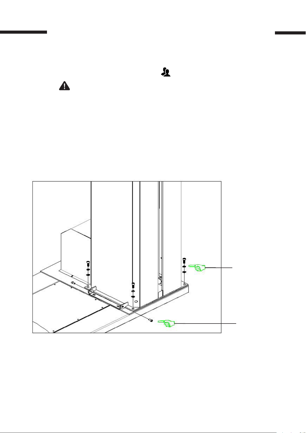
1. Raise the tower upright safely with two people.
2. Tighten the screw between the tower and the turntable base. (See Figure 4)
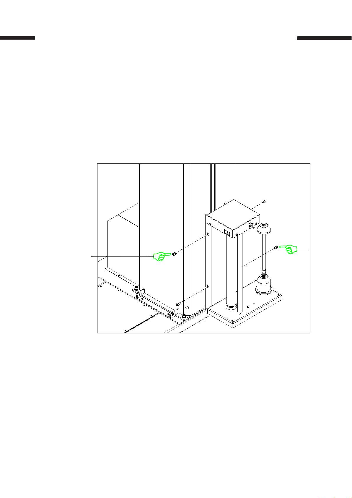
3. Screw the lm carriage into the post. (See Figure 5)
4. Connect to the power supply and perform a ground test before using the machine.
Figure 4
Screw the set of (4)
screws, washers, and
lock washers through
the tower and into the
turntable base securely.
(M10 X 20 screw)
Screw the set of (2)
screws connecting the
tower and turntable.
(M8 x 10 screw)
Page 9
9
Mount the lm carriage
onto the post by fastening
a set of (2) screws.
( M8 x 20 screw)
Figure 5
Page 10
10
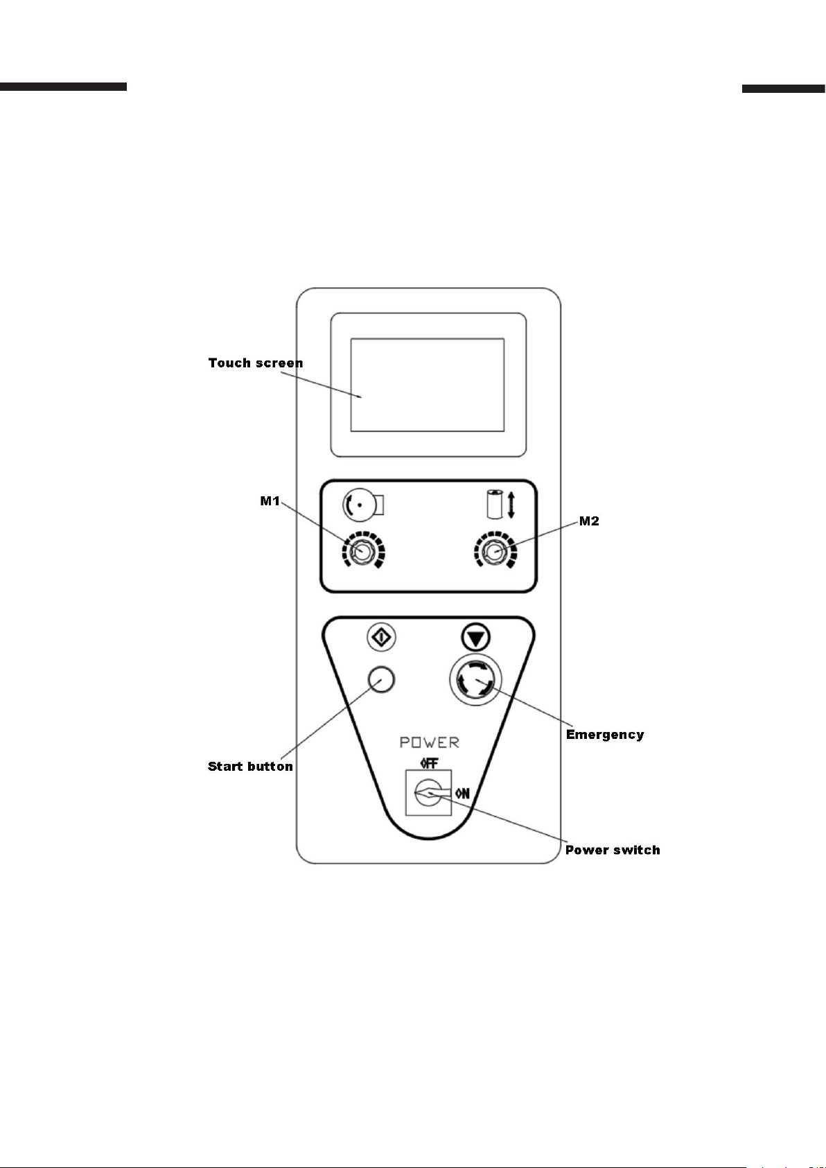
3. Control Panel Buttons
Figure 6
Control Panel Buttons
Page 11

Speed Controlled by M1, M2 Knob
• M1: Control the speed of the turntable motor. The speed range 1~ 10 rpm.
• M2: Control the lifting motor speed.
Start Button has three functions
• The start of the automatic mode starts
• Resume after emergency stop
• Use/cancel the central reinforcement
Emergnecy Stop Button
Press the emergency stop button to stop the machine immediately. Press the button when any emergency occurred during the packaging process. Turn the emergency stop button clockwise to reset the emergency stop button.
11
Power Switch
• OFF, power o the machine
• ON, power on the machine
Page 12

12
Operator Controls
4. Operator Controls
Figure 7 Main menu display
4.1 Manual
Press the manual Interface button in the main menu to display the manual operation.
(See Figure 8)
Carriage up / Carriage down
Manually operate the carriage to move up or down. When this function is pushed, the
button will turn green. To pause the operation, simply push the button again. This
button may be used in conjunction with the Turntable start button.
Turntable start
The Turntable Start button allows you to manually operate the turntable. When this
button is pushed, the button will turn green. Pushing the button again will stop the
turntable. The button may be used in conjunction with the Carriage up/down button.
Reset
Push the Reset button to reset the system operation. The turntable will return to its
home position and the carriage will lower to the initial position.
Page 13

Figure 8 Manual display
4.2 Auto
Press the AUTO button in the main menu to set parameters through the interface
shown in gure 9 .
13
The parameters can be set according to the following packaging requirements:
Bottoms Laps, Top Laps, Lifting Time, Strengthening Laps, and electric eye delay.
Press the white box to set each parameter through the pop-up numerical keyboard
followed by pressing the Enter button.
Once the parameters are set, click the “Save” button on the screen to store the parameters for the assigned group number. A total of ve sets of parameters can be
stored. To use any of the saved parameters, select the group number. (See Figure 9)
NOTE: The parameters and function settings cannot be changed when the machine
is running.
Figure 9 Auto display
Page 14

14
4.3 Input & Output (I/O)
You can check the status of all the sensors and switches on the I/O interface shown
in Figure 10. This display can be used for routine maintenance on the machine.
(See Figure 10)
To return to the main menu, press the EXIT button.
Figure 10 I/O display
4.4 Film Loading
CAUTION!
Be sure EMERGENCY STOP is pushed in before threading the lm and pulled out
when the lm is threaded.
1. Load the lm roll in the lm carriage. (See Figure 11)
2. Follow the lm feed diagram and thread the lm all the way through the rollers.
(See Figure 12)
3. Attach the lm securely to the pallet. Tying the end of the lm in a knot often helps
secure the lm to the pallet.
4. Turn the emergency stop switch clockwise and turn the power on.
Page 15

15
Figure 11
Figure 12
Page 16

16
4.5 Machine Operation
Trial run – Normal System Start-up:
1. Place the packaged pallet on the machine turntable.
2. Thread the lm as instructed and attach it to the product.
3. Turn the power on.
4. Adjust the sensitivity of the photo switch. The machine is adjusted to the factory
setting before delivery.
5. Select either Manual or Auto mode to achieve the user’s packaging requirement.
6. Press the START button to initiate cycle.
NOTE: It is recommendwd to try a trail run to become familiar with the various
parameters, adjustments, and speed controls.
Emergency Stop Condition
1. In the event of an emergency, press the STOP button. This cancels the current
wrapping cycle and immediately stops the system. Figure 13 will display on the
screen.
2. Correct the problem.
3. Turn the STOP button clockwise to reset the stop button and perform the normal
system start-up procedure.
NOTE: If the weight of the package exceeds 1,100lbs. , turn the turntable adjustment
knob M1 counterclockwise prior to pressing the emergency stop button.
Figure 13
Page 17

17
Operation
1. Load the lm roll in the lm carriage and thread the lm according to gure 12.
2. Turn the power on.
3. Adjust the sensitivity of the photo switch. The machine is adjusted to the factory setting
before delivery.
4. Adjust the parameter according to the packing requirements.
5. Trial run: Place the packaged pallet, used for a trial run, on the machine turntable.
Adjust M1 & M2 speed controlled knobs to the desired speed. Packaging operation can be
adjusted by the multiple parameters to achieve the user’s packaging requirement. Once
the user is familiar with the various parameters and adjustments, the user is ready to
operate the machine.
Page 18

18
Maintenance & Troubleshooting
5. Maintenance & Troubleshooting
CAUTION!
All machine maintenance work must be performed with the power supply
disconnected.
1. Keep the machine clean. Use a dry cloth and cleaning agent to clean the machine.
Do not use solvent water to clean the machine to prevent rusting.
2. Regularly perform maintenance on the machine every 3 – 6 months; frequency
varies with the machine usage. Check for internal dust build up. Check the tightness
of the chain and lubricate the chain in routine maintenance inspections.
WARNING!
Make sure that only qualied personnel perform inspection, troubleshooting and
part replacement.
CAUTION!
Disconnect all power, including external control power that may be present before
servicing the frequency drive controllers.
Page 19

19
OPERATING ISSUES CAUSES RECOMMENDATIONS
Table 2
The machine is
not powering on
Turntable does
not run.
Main Power is turned o.
Machine not plugged into
110VAC outlet.
Faulty power supply
Internal battery not charged.
PLC Failure
No display on PLC screen
Fuse Burn Replace the fuse
Pallet overweight Reduce the pallet weight
Chain falls o
Loose chain
Check the power going into the machi-
ne. Verify that the switch is turned on.
Verify the voltage going to the machine
matches the power supply labels on the
power module.
Replace new PLC
Check the chain transmission mechanisn (loosen the chassis screws, remove
the turntable cover and check wheather
the chain and tension are abnormal.
Film carriage
malfunction
The output protection of the inverter
will ash the fault code on the inverter.
Inverter failure or damage
Limit switch failure or damage Overhaul or replace the limit switch
Photocell failure or damage Overhaul or replace the photocell
Loose chain or interference
PLC Failure
Carriage Up/Down button is
unresponsive
Inverter failure or damage
Motor Failure Overhaul the lifting motor
Look up the corresponding fault code and
troubleshoot method. Replace inverter if
damaged.
Overhaul the vertical lifting chain
system
Replace the PLC
Troubleshoot and replace inverter if
damaged
Page 20

20
Components & Parts
6. Components & Parts
Turntable
Figure 14
Page 21

Table 3
Turntable
No. Part no. Description Qty.
1 GB/T825 Hook M10 1
2 GB/T70.3 Hex scew M10x25 3
3 10000000510 Disc 1
4 GB/T70.2 Hex at cap head screw M5 x 10 4
5 XT4505-0126 Protection cover 1
6 GB/T70.1 Hex screw M10x50 4
7 10000000486G Motor chain pulley: 12B, 14 teeth 1
21
8 CV-32-750-30S Gear motor 1
9 GB/T1243 Chain: 12B, 174 keys 1
10 10000000695 Chain noise reducer 2
11 XT45N-0110 Switch holder 1
12 PL-O5PN Switch 1
13 XT4505-0129-V1 Tension pulley: 12BZ11 1
14 XT4505-0135-V1 Protection cover support block 1
15 10000000693 Center turntable pulley 1
16 10010000617 Turntable roller 12
17 8020-0506 Motor base 4
18 10000000698 Tension pulley bracket 1
Page 22

22
1
2
3
4
5
6
7
8
9
10
11
12
13
14
15
16
18
19
20
21
22
23
24
25
26
17
Film Carriage
Figure 15
Page 23

Table 4
Film Carriage
No. Part No. Description Qty.
1 XT15Z-02-V2 Bottom xed plate assembly 1
2 XT45M-19 Film roll: welding assembly 1
3 10000000033 Film roll: bottom seat 1
4 10000000035-VI Spring plate 1
5 10000000030 Spring 1
6 20545000404-V1 Lock ring 1
7 10000000034 Film roll: top seat 1
8 XT45Z-06-V1 Rubber roller unit 1
9 GB/T1096 6*6*25 key 1
10 GB/T276 Bearing 6004 2
23
11 XT45M-12-V3 Rubber roller bearing seat 2
12 XT4508A-0205 Lock sleeve 1
13 XT45Z-010-V2 Film carriage top plate 1
14 XT45Z-11-V1 Brake shaft 1
15 XT45Z-11-1 Rubber belt 218L*12W*2T mm 1
16 XT45Z-03-V1 Top lm carriage cover 1
17 XT45Z-09 Shaft lock ring 1
18 10000000046 Tension friction wheel 1
19 XT45Z-10-V1 Belt holder 1
20 FR-2MX Photocell 1
21 M8X20 Star knob 1
22 XT45M-14 Guide roller 2
23 XT45Z-16 Swith install plate 1
24 KW3-0Z-2 Microswitch w/ wheel 1
25 QB/T3876 Hinge: 50 x 38 2
26 XT45Z-15-V3 Safety plate 1
Page 24

24
18
19
22 23 24
15
16
2120
17
14
26
28
27
13
30
29
313233
1
4
5
6
7
8
9
10
11
12
2
3
34
25
Tower and Lift
Figure 16
Page 25

Table 5
Tower and Lift Assembly
No. Part No. Description Qty.
1 XT45O5-0201-V2 Tower body 1
2 Z15G 1703 15A Door safety switch 1
3 XT45O5-0206 Z type holder 1
4 XT4505-0204 Tower body top cover 1
5 XT45O5-0203 Tower body top protection plate 1
6 XT4515-02-002 Door 1
7 Locker 2
8 HMIGXU3500 Touch screen (Schneider) 1
25
9
10 HB1-BA31 Start button 1
11 HB2-BS542 Emergency stop switch 1
12 TCS4S295 Power switch 1
13 10000000549 Lifting motor chain wheel: 14 teeth 2
14 08B P12.7 Chain 08B (12.7), 314 joint 2
15 GB/T893.1 D35 Locking ring 35 2
16 GB/T276 Bearing: 6202-zz 2
17 XT4505S-0113 Chain wheel: 08b 14 teeth 2
18 XT4505S-0110-V2 Electrical housing 1
19 XT4505S-0115-V2 L Channel bracket 1
20 XT4505S-0105 Electrical component storage 1
21 XT4505S-01-17-V2 Bottom limit switch seat 1
22 TZ-8108 Limit switch 2
RV24YN 20S B502 +
MF-A03
Potentiometer + Knob 3
23 XT4505S-010702-V4 Inner tower assembly 1
24 XT4505S-0104 Guide rail 2
25 XT4505S-0103G Sliding block 4
26 XT4505S-0102-V1 Drive shaft 1
27 XT4505S-0109-V1 Connection board assembly 1
28 XT4505S-0111 Screw 4
29 GB/T1095 Key 6*6*25 2
30 XT4505S-0101 Shaft 1
31 XT4505S-0108 Top lifting board 1
32 XT4505S-010701 Motor seat 1
33 NMRV050 Lifting assembly 1
Page 26

26
Electrical Components
Figure 17
Page 27

Table 6
Electrical Floor Components
No Part no. Description Qty.
1 RT18-32,2P,16A,Fuse 10X38 Circuit Breaker 2
2 RT18-32,1P,2A,Fuse 10X38 Circuit Breaker 1
3 LRS-50-24 Switch power 1
4 218LDA24DRN PLC 1
5 ATV12H075M2 Turntable inverter 1
27
6 ATV12H037M2 Lifting inverter 1
8 Z15G1703 Safety Switch 1
9 30 port Terminal block 1
Page 28

28
Electrical Diagram
Page 29

29
Diagram 1
Page 30

30
Power Supply: AC110V, 60 Hz
Page 31

31
Diagram 2
Page 32

 Loading...