

Global Industrial 300683 User Manual
Instruction Manual
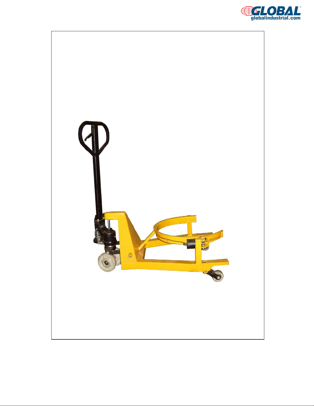
Hydraulic Drum Truck
Note:
Owner/Operator must read and understand this instruction
manual before using the hydraulic drum truck.
www.globalindustrial.com

GENERAL INTRODUCTION
Thank you for choosing our hydraulic drum truck. For your safety and correct operation, please
carefully read the manual before use.
Hydraulic drum truck is a special tool to move the drum in short distance. The structure of the
whole pallet truck is easy, it is convenient in use, safe and reliable. During the process of using,
first place Part No. H106 in the LOWER position, lower the frame to the lowest height, push the
hydraulic drum truck, place the drum in the hoop, place Part No. H106 in the ASCENT position,
pump the handle, let the frame first holding the drum, then elevate with the drum leaving the
ground (The height of the clearance is up to the operator’s need). Then place Part No. H106 in
the NEUTRAL position, push the hydraulic drum truck, unload the drum in the destined area.
Finally, place Part No. H106 in the LOWER position, lower the frame to the lowest height and
loose the pawl, drag the hydraulic drum truck out.
(Three positions of setting Part No. H106, please see Fig. 1)
1. GENERAL SPECIFICATIONS
Model HJ365
Capacity (lbs) 800
Min. Hoop Height (mm) 390
Max. Hoop Height (mm) 270
Hoop Radius (mm) 290
Load Wheel Diameter (mm)
Steering Wheel Diameter (mm) Ø160
Net Weight (kg) 53
Ø80×38 Nylon
2. TO AT TACH HANDLE TO PUMP UNIT
2.1 Loosen the setting screw (140H) on the crank link (139H).
2.2 Remove three screws (H109) and three spring washers (H110) from the base (103).
2.3 Place the handle (H101, H101A, H101(JR), H101(FR)) on the base (103), please note: Feed
the rod and chain
(H107) through the centre of the base (103) and axle (109).
2.4 Insert three screws (H109) with spring washers (H110) into the base (103). Then tighten
them securely .
2.5 Raise the crank link (139H) and put the pin on rod and chain (H107) into the groove of crank
link (139H).
3. TO ADJUST RELEASE DEVICE
On the handle of the hydraulic drum truck, you will find the control lever (H1 06) which ca n be
set in three positions (See Fig. 1):
LOWER=to lower the forks; NEUTRAL=to move the load; ASCENT=to raise the forks.
After assembling the handle, you can adjust the three positions.
3.1 First tighten the setting screw (140H) on the crank link (139H) until the LOWER position
function works.
1

3.2 If the forks elevate while pumping in the NEUTRAL position, turn the setting screw (140H)
clockwise until pumping the handle does not raise the forks and the NEUTRAL position
functions correctly.
3.3 If the forks descend while pumping in the NEUTRAL position, turn the setting screw (140H)
counter-clockwise until the forks do not lower.
3.4 If the forks do not descend when the control lever (H106) is in the LOWER position, turn the
setting screw (140H) clockwise until raising the control lever (H106) lowers the forks. Then
check the NEUTRAL position as per item 3. 2 and 3.3.
3.5 If the forks do not lift while pumping in the ASCENT position, turn the setting screw (140H)
counter-clockwise until the forks elevate while pumping in the ASCENT position. Then
check the NEUTRAL and LOWER position as per item 3.2, 3.3 and 3.4.
4. MAINTENANCE
4.1 OIL
Please check the oil level every six months. Add oil when the forks in the lowered position.
Add or change the hydraulic oil according to the table below.
Temperature Oil
-20℃~+40℃ L-HV46 Hydraulic oil
4.2 HOW TO EXPEL AIR FROM THE PUMP UNIT
Air may enter the unit when the seals are replaced. Lift the control lever (H106) to the
LOWER position, then move handle up and down for several times.
4.3 DAILY CHECK AND MAINTENANCE
Daily check of the hydraulic drum truck can limit wear and tear of the unit. Pay special
attention to the wheels, the axles, the ha ndle, the f orks and li f t, lower, hold control. When the
truck is not being used, it should be left in the lowered position.
4.4 LUBRICATION
Use motor oil or grease to lubricate all moveable parts.
5. SAFETY RULES AND OPERATING INSTRUCTIONS
For safe operation of the Hydraulic Drum Truck please read all warning signs and
instructions here and on the hydraulic drum truck prior to use.
5.1 Safety rules
To avoid hazardous situations, you should obey the following rules:
1) Fall Hazard
Do not use as a personnel lifting platform or step.
2) Tip-over Hazards
Do not overload the machine.
The machine can be only used on a firm, level surface.
Do not use the machine on the condition of drop-offs, holes, bumps, debris, unstable
surfaces or other possible hazardous conditions.
The machine can be only used in the light environment of at least 50LUX.
3) Collision Hazard
2
 Loading...