

Page 1
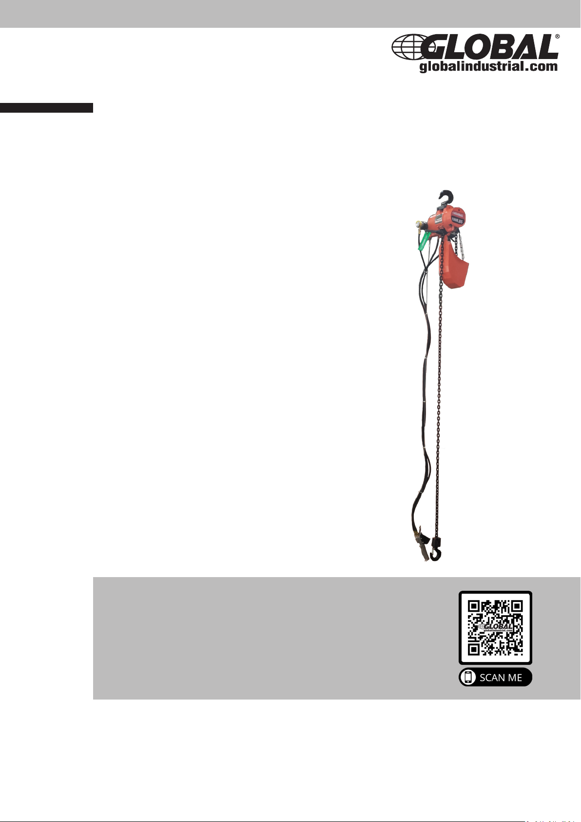
Air Chain Hoist
User Manual
Model no. 298625, 298626, 298627
Table of Contents
General Data pg. 2
Safety Information pg. 4
Installation & Set up pg. 4
Operation pg. 6
Maintenance & Inspection pg. 7
Disassembly & Reassembly
• Disassembly pg. 8
• Reassembly pg. 11
• Testing Hoist pg. 14
• Pendant Throttle Control Assembly pg. 15
Inspection Schedule & Maintenance Report pg. 16
Parts List pg. 17
Troubleshooting pg. 25
Page 2
2
Global Industrial Hoists are high quality hoists made with a tough, compact housing for easy
operation, transportation and storage. These are made for long lasting use in industrial
environments. Very ecient with dierent speed controls and ability to lift dierent load
capacities.
PLEASE READ THESE INSTRUCTIONS COMPLETELY AND SAVE FOR REFERENCE. UPON
RECEIVING, INSPECT THE UNIT FOR ANY DAMAGE OR MISSING PARTS. IF DAMAGE IS
EVIDENT, NOTIFY THE CARRIER IMMEDIATELY TO FILE A CLAIM. THESE PRODUCTS MUST
BE HANDLED WITH CAUTION BY TRAINED OPERATORS WITH PROPER SAFETY GEAR AND
EQUIPMENT. FAILURE TO COMPLY WITH INSTRUCTIONS COULD RESULT IN SERIOUS INJURY.
PLEASE CONTACT GLOBAL INDUSTRIAL CUSTOMER SERVICE (1-800-645-2986) FOR ANY
ISSUES OR REPLACEMENT PARTS.
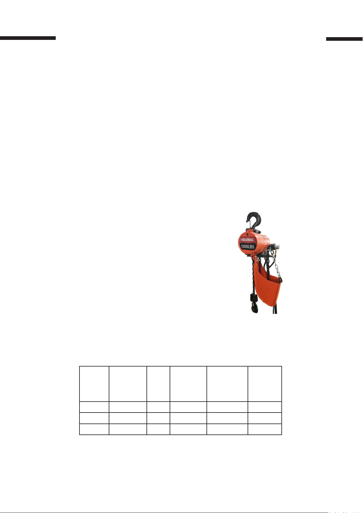
GENERAL DATA:
• Rated Loads: 300 lb, 500 lb, 1000 lb.
• Type: Link Chain
• Air Pressure Recommended: 90 PSI
• Air Consumption: 48 SCFM at 90 PSI
• Net Weight (Basic Hoist): 36 lbs
• Suspension: Hook
• Control: Pendant Throttle
• Air Inlet Size: 3/8 NPTF
• Air Supply Hose: 1/2 I.D. min
• Air Exhaust: 1/2 NPTF
Lifting
Model
298625 300 46 84 65 10
Capacity
[lb.]
Wt.
[lb.]
Speed
Max
[fpm]
Lowering
Speed Max
[fpm]
Image 1
Lifting
Height
[Ft.]
298626 500 46 65 95 10
298627 1000 46 45 120 10
Page 3
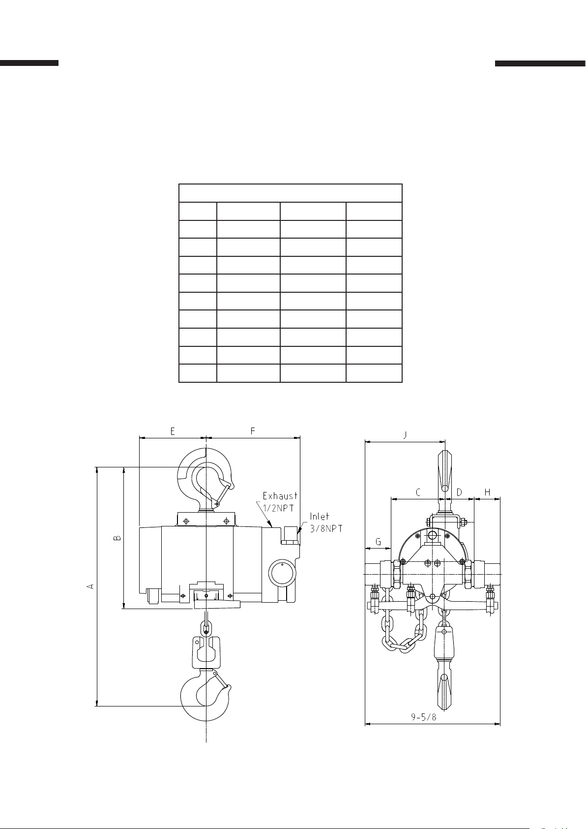
Hoist Dimensions
3
Dimensions [inches]
Ref. 298625 298626 298627
A 15.25 15.25 15.25
B 10.25 10.25 10.25
C 4.75 4.75 4.75
D 1.75 1.75 1.75
E 7.0625 7.0625 7.0625
F 5.0625 5.0625 5.0625
G 0.9375 0.9375 0.9375
H 2.1875 2.1875 2.1875
I 5.6875 5.6875 5.6875
1
U D
1 3
2
2
3
1/2TON
Page 4

4
SAFETY INFORMATION
PLEASE READ THOROUGHLY AND CAREFULLY. IMPROPER OPERATION OR FAILURE TO
FOLLOW THESE PRECAUTIONS COULD RESULT IN SERIOUS INJURY.
DO NOT operate a damaged hoist.
DO NOT modify the hoist in any way.
DO NOT lift more than max capacity.
DO NOT lift over people, or transport people.
DO NOT wrap chain around load.
DO NOT apply the load to the tip of the hook or the hook latch.
DO NOT operate beyond limits of the load chain travel.
DO NOT leave load supported by the hoist unattended.
DO NOT allow the load chain or hook to be used as an electrical or welding ground.
DO NOT use the hoist’s overload limiting clutch to measure load.
DO NOT use the hoist’s limit switches as routine operating stops.
ALWAYS make sure people remain clear during use.
ALWAYS make sure the load is centered under hoist.
ALWAYS make sure the hoist is securely attached to a suitable support.
ALWAYS take up slack carefully – make sure load is balanced.
ALWAYS stop immediately if the hoist malfunctions and inspect carefully.
ALWAYS check brake function by tightening the hoist prior to each lift operation.
ALWAYS use hook latches and make sure they are closed.
ALWAYS make sure the load is free to move and will clear all obstructions.
ALWAYS avoid swinging the load or hook.
ALWAYS make sure hook travel is in the same direction as shown on the controls.
ALWAYS inspect the hoist regularly and replace damage or worn parts.
ALWAYS lubricate load chain per instructions in this manual.
INSTALLATION & SET UP
Suspending/Mounting the Hoist to Supporting Structure:
1. The structure used to support the hoist must have a load rating equal to or greater than
that of the hoist.
2. The supporting structure must be able to eectively suspend both the weight of the hoist
and the rated load.
3. Proper installation requires that the upper hook is seated in the center of the hook saddle
and the spring safety latch is completely closed.
4. The hoist must be in the same straight line with the load to avoid side forces.
5. If trolley is mounted to a beam, make sure the beam has end stops to prevent the trolley
running o the end of the beam, causing serious injury.
Page 5
5
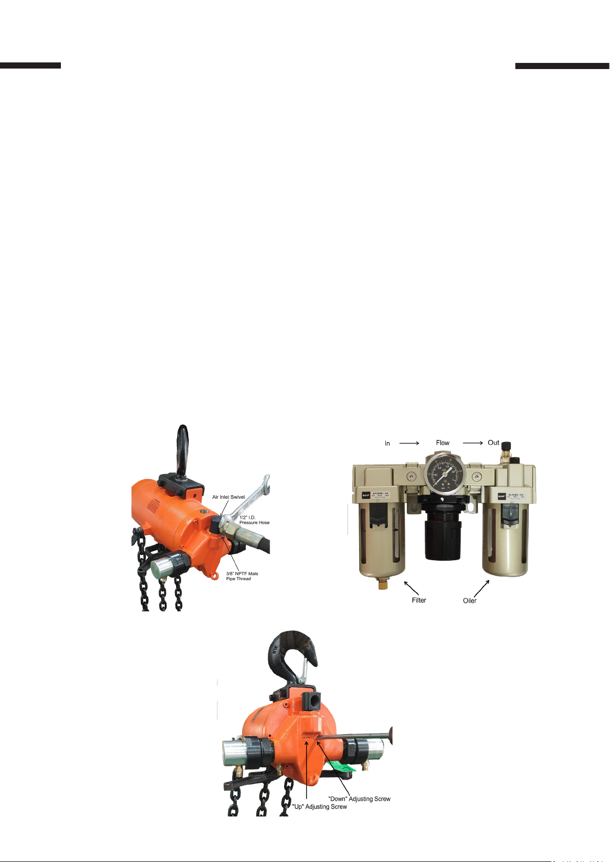
Connecting Hoist to Air Source:
1. Connect hoist to a ltered and lubricated air source with a least 1/2” I.D (see image 2)
2. If the hoist is connected with trolley, the hose must be long enough to reach from air
source.
3. A lter and lubricator unit must be installed between air source and air hose connected to
the hoist to assure the air hoist will receive consistent, clean air ow. (see image 3)
4. DO NOT use multi-viscosity, detergent-type engine oil. USE air hoist motor oil or 10W
machine oil (approx. viscosity 150 SSU @ 100 deg. F). The lubrication rate for air supply
should be 1 drop for every 50-75 cu. Ft. Recommended air pressure is 90 psi.
Speed Adjustments:
1. For lifting speed, the maximum is pre-set. The lowering speed is adjusted to an average
setting between minimum and maximum.
2. To adjust speed, turn the adjusting screw shown in image 4. The speed will be max or min
when the head slots on the adjusting screws are horizontal. Rotate screws 180 deg. In
either direction for full range of speed adjustment.
3. NOTE the max lowering speed with rated load is very high. Adjusting screws should not
be adjusted beyond outer surface of hoist housing.
Image 2
Image 3
Image 4
Page 6
6
OPERATION
The operator should be a trained professional and is responsible for safe use with these
hoists. They must follow the safety guidelines mentioned on page 5 to prevent damage or
injury.
1. Inspect all connections between side hoist frame, hooks, and structural support. Check
all parts (brake, hoist, chain, pins) to make sure there is no damage/distortion. DO NOT
use if there is any damage or distortion. Chain should be lubricated.
2. DO NOT lift more than rated capacity. Overloading can cause deformation or breakage in
the chain/hook and can cause serious injury and damage.
3. Guide load so that it is under control at all times and clear of any personnel.
4. Make sure the hoist is properly mounted to a support with proper air pressure applied.
5. This hoist is equipped with a pendant throttle control with lever type control valve handle
suspended from control cylinders shown in image 5.
6. On the pendant throttle control, depress the throttle lever marked “UP” to lift the load.
7. Depress the throttle lever marked “DOWN” to lower the load.
8. Release the lever to stop either lifting or lowering.
9. The lifting/lowering speed varies by the position of the throttle valve lever being
depressed.
10. The strain cable is designed for pulling trolley suspended hoist when empty or lightly
loaded.
11. Push on load or load chain to traverse heavy
loads. Push on one corner of the load to pivot.
The lower hook will swivel 360 deg. to allow load
to swing to desired position. The upper hook may
rotate so that the hoist will be swung by the side
pulls to face the load, reducing side thrust.
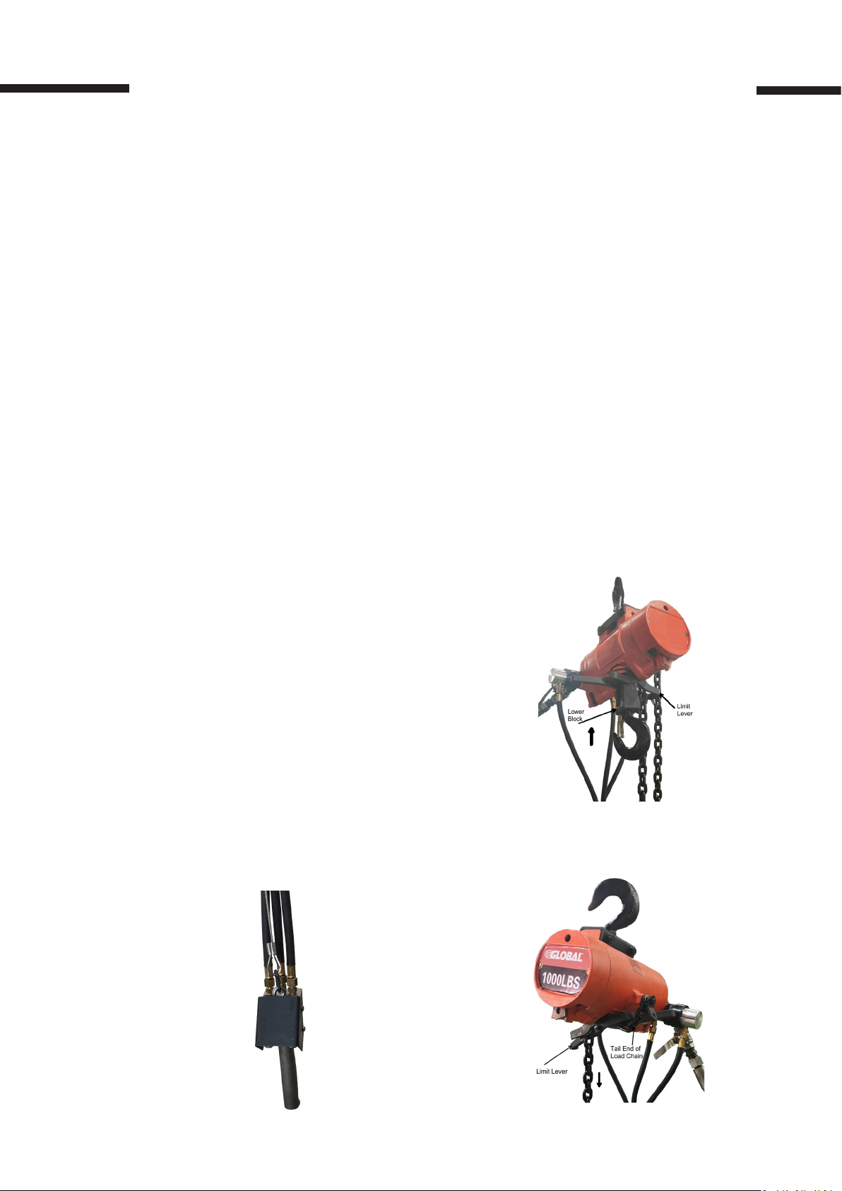
12. Theses hoists are equipped with chain stops and
limit blocks to prevent over travel when lifting or
lowering the load. The control lever will be tripped
by the lower block when it reaches highest
position. The control lever will be tripped by the
tail end of the load chain when it reaches the
lowest position, see images 6 and 7. The control
lever is connected to a shaft which controls air
pressure into the air motor by inlet valve. These
limit stops are only designed for preventive
measures and not to be used as a regular device.
Image 6
Image 5
Image 7
Page 7
7
MAINTENANCE & INSPECTION
Periodic maintenance checks on the hoist components are recommended to make sure
there is no damage. Do not attempt to repair defective parts. Only Global approved that
meet specications for strength and dimensions must be used. Please contact Global
Industrial Customer Service (1-800-645-2986) for replacement chains, hooks, etc.
1. Inspect the chain with load in both chain travel directions. The chain should feed
smoothly into and away from the sprocket. If there are any binds or jumps, apply
lubrication and clean the chain. Check for deformation, distortion or damage to any of the
links at any connection points.
2. Greatest wear usually occurs at high and low lift points. Chain must be replaced before
the case is worn past 0.015” deep as shown in image 8.
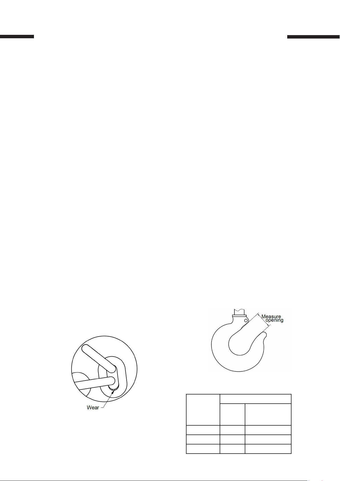
3. Check the hooks for bending, twisting or distortion. The hook must be replaced if it is bent
more than the dimension shown in image 9.
4. Check all hook latches, trolley parts, springs, and load bearing components.
Apply lubricant if necessary and replace any parts as necessary.
5. Check brake function when the hoist is operating. The brake needs adjusting if the load
drifts down before the motor starts. To adjust brake, use a hex key through the hole in
the brake cover, and turn counterclockwise to tighten brake or clockwise to loosen brake.
Lubrication
Regular lubrication enables the hoist to operate at high level with long-lasting service.
1. Air Line Lubricator – It is important to monitor the lubricator as it provides lubrication for
the control valve and motor. ONLY motor oil or machine oil (10W) should be used.
2. Load & Coil Chains – Keep chains clean regularly. Small amounts of lubrication routinely
will increase the performance and life of the chains. Avoid letting the chains run dry.
3. Upper Hook & Control Shaft - Small amounts of SAE60 can be used on the upper hook
shank and the control shaft at bearing points.
Image 9
Image 8
Hook Throat Opening
Hoist Rated
Load (lb.)
300 1-1/8” 1-9/32”
500 1-1/8” 1-9/32”
1000 1-1/8” 1-9/32”
Normal
Opening
Replace Hook
if Opening is
Greater Than
Page 8

8
DISASSEMBLY & REASSEMBLY
For ease of disassembly, the following disassembly steps may not, where conditions permit,
be completed before hoist is removed from its overhead suspension or disconnected from
its air supply. If the hoist is in use, remove the chain container. Remove lower block and load
chain assembly.
Handle the parts with care when disassembling and reassembling the hoist. Carefully apply
pressure evenly when removing and installing parts with press ts. On ball bearing, apply
pressure to the side of the inner or outer race, whichever is adjacent to the mating part. Apply
a thin lm of oil to parts having a tight t when installed.
Diassembly
Removal of Hoist from Overhead Suspension
1. Turn o source of air
2. Operate control to discharge the air from the hoist.
3. Disconnect air hose at inlet swivel
4. Remove hoist from overhead suspension
Removal of Lower Block and Load Chain Assembly
1. Disconnect end of load chain from the tail end. Anchor the side of the hoist frame on
models with single reeved load chain (300, 500, and 1000lb). Remove socket head cap
screw, holding end link to tail end anchor on coil chain. Run the chain out of hoist by
operating control in “lowering” direction when the hoist is connected to an air source. The
chain can be pulled out of the hoist when it is connected to an air source.
2. Run chain out of hoist by operating it in “lowering” direction, and disconnect opposite
end of chain from anchor at side of upper suspension bracket on models with double
reeved chains (2000lb,).
3. Separate load chain from lower block assembly in single reeved 300, 500, and 1000 lb.
models. Drive out small pin securing lower block pin in lower block and push out block pin
to release chain.
4. Lower blocks (300, 500, and 1000lb.) are of a pinned construction, permitting
individual replacement of body, thrust bearing, or hook. To disassemble, drive spring pin
from hook nut: Remove the pin, hold hook nut from turning with drift punch and rotate
hook to unscrew it from nut. Separate hook, bearing shield, needle bearing and tow thrust
washers from body. Hook and nut are drilled at assembly. And they are replaced only as
an assembly.
5. The lower block assembly is disassembled by removing the socket head screws and nuts
holding the body halves together on 2000lb. (double reeved) models.
Removal of Brake Cover, Control Lever and Load Brake
1. For convenience, disconnect control hoses from air cylinders, open strain cable “S” hook
at eye bolt on throttle housing and remove pendant throttle control assembly from hoist on
pendant throttle control. See “Disassembly and Reassembly”, page 8, for disassembly and
reassembly of pendant throttle control.
2. Take out the two screws securing the brake housing cover to frame and lift o the cover.
3. To remove control lever and shaft, drive spring pins from control lever (Image 10) and valve
shifter at end of shaft using a drift punch. Lightly tap valve shifter end of shaft and withdraw
shaft by pulling on brake cam end (Image 11). Valve shifter and control lever will fall free as
shaft is withdrawn.
Page 9
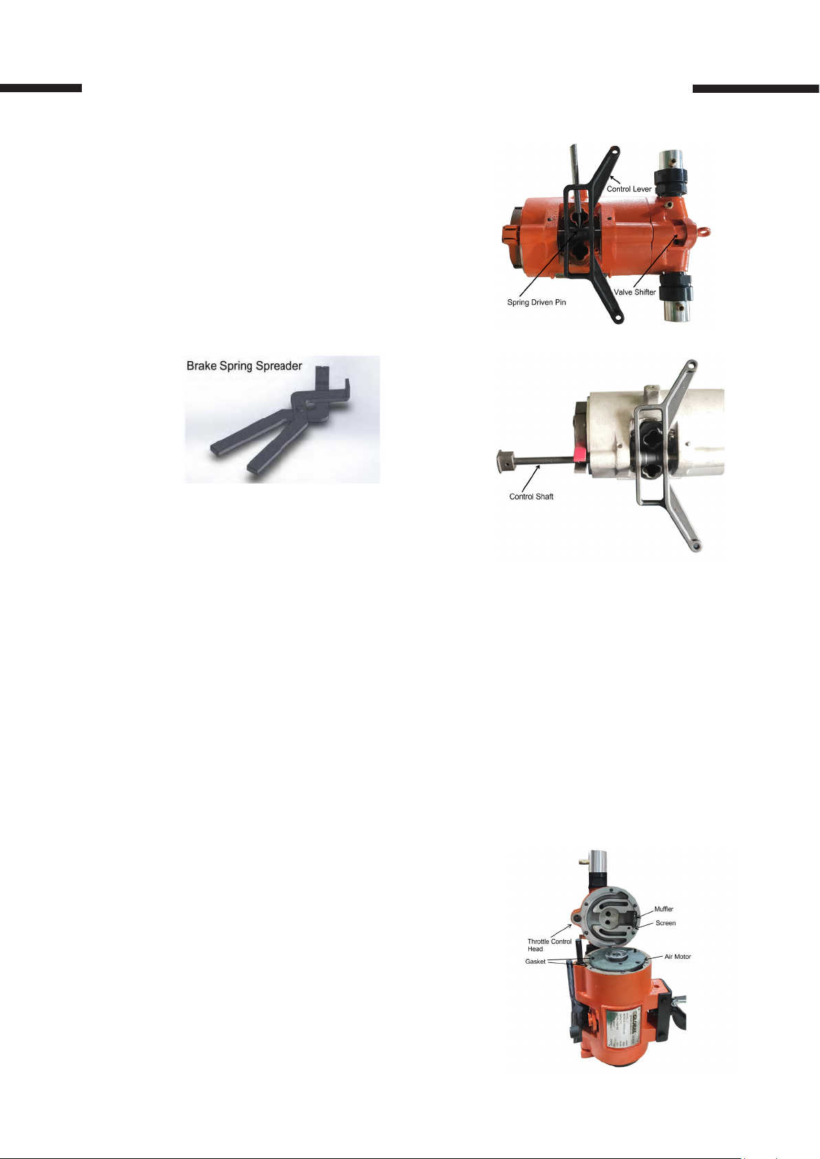
4. Carefully pry brake spring up evenly with a
screwdriver until spring is about halfway o
to remove it. Using brake spring spreader
(Image 12), take out spring from brake arms.
5. Take out brake shoes. Make sure not to lose
steel fulcrum balls.
6. Take out steel balls from recesses sides of
upper brake.
9
Image 10 Driving spring in from
control lever and shaft
Image 12
Image 11 Removing control shaft
Removing control head assembly
1. Take out six socket head screws and lift assembly from frame to remove control head
assembly.
2. Lift muer and screen from recess in control head housing.
3. Take out control cylinder assemblies from each side of control head housing (Image 20).
Then remove valve springs, spring guides and “O” ring seals from valve bore at each side
of housing.
4. The throttle valve is retained in the control head by the valve shifter pin. The pin is
assembled with Loctite on the threads and should not be removed during routine
servicing. Use a hex key to remove pin from bottom of throttle valve if valve is to be
removed (See Image 19). Then remove the valve from bushing in housing. The throttle
valve bushing is pressed into place and honed to provide a .0001 to .0003-inch clearance
with valve. The housing and bushing assembly should be replaced along with the valve if
bushing is scored, worn, or otherwise damaged.
5. Take out air inlet swivel body and bushing from
top of housing. Retain bushing gasket for reuse.
Pull strainer screen from housing bore.
6. Take out retaining ring from bottom of swivel
body and pull o bushing. Take out “O” ring seal
from its groove in bushing.
7. Remove cylinder lock ring to disassemble control cylinder (pendant throttle control models).
Cylinder and cap will come o with lock ring. Lift
out spring. Then remove piston and seal
assembly from cylinder. Piston shaft “O” ring
seal and retainer washer will drop out as piston
is removed.
Image 13 Removing control head
Page 10

10
Removal and Disassembly of Air Motor
1. Place entire unit on motor end and lift frame straight up as shown to remove air motor
from hoist frame. DO NOT tap on end of motor shaft since it will destroy critical rotor
alignment and damage motor. Motor may be grasped at bearing boss on the dead end
plate to assist in removal if necessary.
2. The motor should not be disassembled. However, if the blades needs to be replaced, the
dead (opposite drive end) end plate can be removed to inspect the blades.
3. Removal of dead end plate requires a puller to take out the end plate bearing
from the shaft.
4. Take out three button head cap screws from
dead end plate. Attach puller to end plate with
two 1/4-28 screws. Be careful to NOT turn
them into end plate more than 1/4 inch, thus
hitting and damaging rotor. Turn puller screw
against motor shaft to remove end plate.
5. Check for worn or damaged blades. Check end
plate, rotor, and body for damage. The end
plates and body are not serviced separately
since they are matched and doweled at
assembly. Replace motor if there is signicant
damage.
Image 14 Removing Motor from Frame
Removal of Brake Wheel, Internal Load Gears, and Sprocket
1. Rotate brake wheel until the holes in web are aligned with four socket head cap screws.
Then lift brake wheel o (Image 15). Remove screws, then lift brake wheel o (Image 16)
after prying up lightly and evenly with screwdriver to free ball bearing. Press o the ball
bearing and clamp plate after removing retaining ring from wheel hub.
2. Take out four socket head screws securing gear plate to frame and lift o plate and in-
termediate gears as a unit (Image 17). Do not remove the two socket head screws from
ange around brake wheel bearing hole (Image 16) unless it is necessary to replace intermediate gear.
3. Take out four llister head screws attaching chain guide and stripper assembly to hoist
frame. This will free guide to allow sprocket to be pulled through it as it is removed in step
(5) (See Image 18).
4. Rotate internal gear (Image 17) to make the holes in web align with six socket head screws
securing bearing clamp plate to frame. Remove internal gear, chain sprocket and ball
bearings as a unit (Image 18).
5. Remove retaining ring and pull outer ball bearing from sprocket to disassemble
intermediate gear, sprocket and ball bearing assembly. Take out spindle nut from other
end of sprocket and pull internal gear free of sprocket shaft. Take out clamp plate and
pull o remaining ball bearing.
Cleaning and Inspection
All parts should be thoroughly cleaned and inspected to determine their serviceability
before reassembly. Replace the parts if they are excessively worn or damaged. Minor nicks
and scratches should be led to remove raised edges.
NOTE: Do not wash the bearings that are sealed. They are lubricated at the factory for normal
life of the bearing.
Page 11

11
Image 15 Removing Cap Screw
Securing Bearing Clamp Plate
Image 17 Removing gear plate and
intermediate gears
Image 16 Removing Brake Wheel and
Ball Bearing Assembly
Image 18 Removing internal gear, chain
sprocket and ball bearing.
Reassembly
Follow the procedure that is in reverse order of the disassembly steps to reassemble hoist
Assembly of Motor
CAUTION
1. The full set of blades should be replaced if any blade replacement is required. Blades
must be installed so that the edges with chamfered corners face down into the slots.
2. Reassemble end plate and bearing as follows. Remove dowel pins locating end plate to
body. Support shaft and press bearing onto shaft, using a drift that contacts both inner
and outer race of bearing. To make sure the bearing is not pressed onto shaft so far as
to bow the end plate, use a feeler gauge between end plate and body. Align dowel pin
holes in end plate with those in body and assemble pins. Assemble three button head
cap screws.
3. The only eld service recommended on air motors is rotor blade replacement
(See “Disassembly and Reassembly”, page 8).
4. Use small amount of Air Hoist Motor Oil or good grade 10W machine oil (approximate
viscosity 150 SSU at 100°F) to lubricate motor. Multi-viscosity, detergent type engine oil
is not recommended.
Page 12

12
Assembly of Control Head
Observe these precautions at reassembly of control head and throttle valve:
1. Lightly oil throttle valve and bushing with SAE 20 oil. Assemble valve with threaded hole
facing slot at bottom of bushing in housing (Image 19) if shifter pin was removed from
valve. Shifter pin should be assembled with loctite. Take extreme care NOT to get any
loctite on valve outside diameter since it will lock up valve and scrap the complete head
assembly.
NOTE: Before installing, apply lubricating oil to “O” ring and “U” seals.
2. Use new “O” ring seals at each end of valve. Install spring guides and valve springs in
bores on each side of housing and secure with control cylinders. Use new “O” ring gaskets.
3. Use new “U” type seals on piston heads and “O” ring seals on piston stems at reassembly
of control cylinder (pendant throttle control models). Ensure “U” type seals face direction
illustrated in Image 20.
4. Use new “O” ring gaskets on adjusting screws. Turn screws in until heads are ush or
slightly below face of housing when installing them in control head housing. Adjustment
is accomplished during testing of hoist.
5. Install a new “O” ring seal inside swivel bushing at reassembly of screen and air inlet
swivel.
6. Use a new motor-to-head air seal gasket and a new head-to-frame gasket in mounting
control head housing on hoist.
Image 19 Section View Showing
Assembly of Throttle Valve,
Spring and Valve Shifter in
Control Head.
Image 20 Section View Showing
Assembly of Control Cylinder on
Control Head (Pendant Throttle
Control Models)
Page 13

13
Assembly of Brake
Replace brake shoes if the brake linings show excessive wear. The brake wheel assembly
goes into position rst and is fastened in place by the four screws in reassembling the brake
(See “Disassembly and Reassembly”, Page 8, Image 16). Then put the steel fulcrum balls in
their receiving cup, using a small amount of thick grease to hold them in place. Retract the
balls completely into the receiving cups. Then put the shoes up to the fulcrum balls and
brake wheel. Replace the brake spring, using the spreader tool to start the spring over the
shoes (See Page 9, Image 12). Tap the spring into place. Adjust brake shoes per instructions
in Image 21.
1. Brake adjustment at reassembly: Turn screw
“A” in until arms pivot on fulcrum ball to make
“C” = .010-.015”.
2. Checking adjustment without load: Without
load, and with air turned o, open brake arms
manually by operating limit lever to see if
brake wheel can be turned freely by hand.
The brake may not be properly adjusted if
wheel refuses to run. Recheck adjustment.
Then check for possible damage, such as
bent brake arms, improper lining, brake cam
slippage or other malfunctions in the unit if
the wheel does not turn freely.
3. Brake adjustment with load:
. a. With load on hook, press “UP” lever, slowly!
Load must not creep down before motor
starts. Turn adjusting screw out as required.
b. Stop brake and hold load in both directions.
Image 21 Brake Adjustments
Installation of Load Chain
Make sure the weld on the second link faces “out” or away from the sprocket when
installing coil chain on the hoist (See Image 22). Then with the air o, brake cover removed,
and brake shoes locked in “open” position (with wedge between control lever and hoist
body), turn brake wheel in “hoist” direction and feed chain in through lever control into
chain sprocket. Supply the chain through, approximately 15” to 16”, the tail chain side of
the hoist. Take the rst link and move it up (do not twist) (See Image 22) to the frame boss
and fasten in place. The rest of the chain can be pulled through, and then the lower block
fastened in place (on single reeved hoist). On double reeved hoist, allow approximately 17”
to 18” of chain to hang on the lifting direction side (See Image 23). Run the lower block
assembly onto chain and swing (do not twist) the remainder of the chain up and attach
to lug on suspension bracket. Remove wedge from between lever and frame and replace
covers.
NOTE: Do not twist the chain. Position the link welds as shown in Image 23
Page 14

14
Testing Hoist
Hoist should be tested to insure proper operation after completion of assembly and before
placing hoist in service. Test as follow: Suspend hoist from an overhead supporting member
of sucient strength to carry combined weight of hoist and rated load; connect to air supply
of correct pressure; perform the following checks and adjustments.
Check Control Operation
Depress lever on pendant control briey to determine that hook travels in the direction to
correspond with control being operated. The control hoses are improperly installed if load
hook travels in a direction opposite to control being operated. When each lever on the handle
is fully depressed, the control lever should attain a full throw with pendant control. The set
screw in the corresponding control cylinder should be turned in if full movement of control
lever is not accomplished. The set screw should be turned out if full movement occurs before
lever is fully depressed. The screw should not extend beyond end of cylinder.
Check Hoist Under Rated Load
Attach rated load to lower hook and check hoist operation.
1. Operate hoist to raise load. Hoist should stop and hold load at that level when control is
released.
2. Operate hoist to lower load from a short distance. Then release control. The hoist should
stop and keep the load at that level.
3. Operate hoist to lower load and observe rate of speed at which load descends. Adjust
lowering and hoisting speeds to the desired rate of speed as outlined in “Speed
Adjustment”, page 5.
WARNING
Do not lift more than rated load except for test purposes. It can cause chain breakage, hook
deformation and other failures which can result in serious injury and damage. If any load
sustaining parts have been altered, replaced or repaired, hoist should be tested to load at
125% of rated capacity by a designated, qualied person, with a written report recording test
load, as recommended in ANSI B30.16 Safety Standards.
Page 15

15
Image 22 Installing Single Reeved Load
Chain (300, 500, and 1000 lb. models)
Pendant Throttle Control Assembly
The pendant throttle control assembly will require some maintenance attention after long
periods of use. To service the control handle assembly, cut o air supply, bleed air from hoist
and control, and disconnect hoses and strain cable at control handle. Disassemble and
reassemble control handle as follows.
Disassembly
1. Take out four screws and lift control lever guard from handle.
2. Drive lever pin from handle housing and separate two control levers from housing.
3. Using a suitable spanner tool, unscrew bushings and valves from handle housing. Take
out air seal gaskets from bushing seats in the handle assembly. Take out “O” ring seals
from ends of valves and pull valves and valve springs from bushings. Take out “O” ring
gaskets from bushings.
Reassembly
1. Clean all parts with cleaning solvent and carefully inspect for wear or damage before
reassembly.
2. Install new air seal gaskets on bushing seats in the handle housing.
3. Install new “O” ring gaskets on valve bushings. Insert springs and valves in bushings.
Install new “O” ring seals on ends of valves. Then reinstall valves and bushings in handle
housing using spanner tool. Lubricate “O” rings before reassembly.
4. Put control levers on housing, align holes and install lever pin.
5. Position guard over levers and secure to housing with four machine screws.
6. Control handle assembly should be reinstalled on hoist. Attach control hoses to handle
housing as outlined in “Disassembly and Reassembly”, page 8, page 13.
Image 23 Installing Double Reeved
Load Chain (2000 lb. Model)
Page 16

16
INSPECTION SCHEDULE AND MAINTENANCE REPORT
HOIST MODEL NO.
RATED LOAD:
LOCATION IN PLANT:
COMPONENT, UNIT OR PART
and location on hoist
COMPONENT, UNIT
LOCATION
HOIST
OR PART
Motor
Motor Brake
Hook Latch Operation
Gears, Shafts & Bearings
Upper Block & Hook
Upper Block & Idler Sprockets
Hook & Throat Opening
Load Chain
Load Sprocket
Guards
Limit Lever
Load Chain Reeving
Air Hose
298625 298626 298627
300lb. 500lb. 1000lb.
*Recommen-
ded
Inspection
Interval
MONTHLY
SEMIANNUAL
(Check column best indicating condition when
part or unit is inspected. Use note column to the
GOOD
ANNUAL
X
INSPECTION FREQUENCY
MONTHLY ANNUAL SEMI-ANNUAL
INSPECTED BY: DATE:
CONDITION
right if condition is not listed below.)
ADJUSTMENT
REPAIR REQUIRED (Loose
REQUIRED
Parts or Wires)
REPLACEMENT
LUBRICATION REQ.
(Worn or Damaged)
(Low Oil or Grease
Rust or Corrosion)
CORRECTIVE ACTION NOTES
CLEANING OR
PAINTING REQUIRED
Record Hook Throat Opening
NOTES
DAT E
STATION
Pendant Throttle
CONTROL
Frame
Wheels
Wheels Spacing on Beam
Bumpers
TROLLEY
Guards
Hand Chain & Wheel
Air Lines & Valves
Filters
Lubricators
AIR SYSTEM
Regulators
Monorail Joints
monorail
RUNWAYS
General Condition
Load Attachment Chains
Rope Slings & Connections
MISC.
Change Gearcase Lub
Req. Warning Labels
Grease Wheels
In Accordance with Manufacture Specs.
Drained (daily)
Filled (when needed)
If equipped with grease fittings on axles
INSPECTION INTERVAL SIGNED & DATED REPORT REQUIRED - OSHA X MAGNETIC PARTICLE OR EQUIVALENT EXAMINATION REQUIRED
Page 17

Parts List
17
* Denotes Parts Aviliable
Ref.
no
1 Bolt -Suspension Bracket 2 2 2 2
2 Lockwasher -Shakeproof, External (8mm) 2 2 2 2
3 Nut -Hex, Cadmium Plated (M8×1mm) 2 2 2 2
4* Hook and Bracket Assembly - Suspension
(Includes Ref. No. 5 thru 13)
5 Hook and Nut Assembly -Upper (Includes Ref. No. 6) 1 1 1
6 Latch Kit 1 1 1
7 Bushing -Machinery 1 1 1
8 Bracket - Suspension 1 1 1
9a Washer -Thrust, Bearing (ISO3031-WS81103) 1 1 1
9b Washer -Thrust, Bearing (ISO3031-GS81103) 1 1 1
10 Bearing Assembly –Needle (ISO3031-AXK1730) 1 1 1
11 Shield -Bearing 1 1 1
Description
300
lb.
1 1 1
Quantity
500
lb.
1000
lb.
2000
lb.
12 Nut -Hook 1 1 1
13 Pin -Spring Drive (5×32mm) 1 1 1
14 Screw -Hex Socket Head Cap (M6×25mm) 1 1 1 1
15 Washer -Flat (8mm) 1 1 1 1
16* Cover -Brake Housing 1 1 1 1
17 Screw -Slotted Head (M4×35mm) 2 2 2 2
Page 18

18
Ref.
no
18* Shaft -Control 1 1 1 1
19* Bushing -Oilite, Control Shaft 3 3 3 3
Chain -Load, Coil Type (11’-5” Lg.) 1 (10’) 1 (10’) 1 (10’)
20*
21* Lever -Control 1 1 1 1
22* Block Assembly -Lower (1/4 Ton) (Incl. Ref. No 23 thru 30) 1 1 1
26a Washer - Thrust, Bearing ( ISO3031-GS81103) 1 1 1
26b Washer - Thrust, Bearing ( ISO3031-WS81103) 1 1 1
Chain -Load, Coil Type (22’-7” Lg.) 1 (20’) 1 (20’) 1 (20’) 1 (10’)
Chain -Load, Coil Type (44’-8” Lg.) 1 (20’)
23 Body -Lower Block 1 1 1
24 Latch Kit 1 1 1
25 Hook and Nut Assembly (With Latch) 1 1 1
27 Bearing Assembly –Needle ( ISO3031-AXK1730) 1 1 1
28 Shield -Bearing 1 1 1
Pin -Spring Drive (5×32mm)
29 1 1 1
Description
300
lb.
500
lb.
1000
lb.
2000
lb.
30 Nut -Hook 1 1 1
31* 1 1 1
32* Pin -Connecting, Lower Block 1 1 1
33* Pin -Spring Drive, Control Lever (4× 18mm) 1 1 1 1
34* Block Assembly -Lower(1 Ton, Includes Ref. No. 35 thru 42) 1
43* Hook & Bracket Assembly (With Latch) (Incl. Ref. No. 44-46) 1
Pin -Spring Drive (2 28mm)
35 Body -Lower Block (Pair) 1
36 Bearing Assembly –Needle (ISO10001-HK2214) 2
37 Washer 2
38 Sprocket -Coil Chain 1
39 Screw -Socket Head Cap (M6×45mm) 3
40 Latch Kit -Lower Hook 1
41 Hook, Bearing and Nut Assembly (With Latch) 1
42 Nut -Hex, Self-Locking (M6×20mm) 3
44 Pin –Cotter (2 x 28mm) 2
45 Pin -Chain Anchor 1
46 Latch Kit 1
×
47* Frame Assembly (Include Ref. No. 19) 1 1 1 1
48 Lockwasher –Spring (4mm) 2 2 2 2
49* Label -Rated Load
300 lb. 1
500 lb. 1
1000 lb. 1
2000 lb. 1
Page 19

19
Page 20

20
Ref. no Description Quantity
1* Ring-Retaining, External (25mm) 1
2 Bearing Assembly-Ball, Sprocket (ISO3290-6005-2Z) 1
3* Guide and Stripper Assembly-Chain (Coil Type Only) 1
4* Sprocket -Chain (Coil Type Only) 1
5 Lockwasher -Shakeproof, Internal (6mm) 4
6 4
7 Bearing Assembly-Ball,Sprocket (ISO3290-6006-2Z) 1
8* Plate-Clamp, Bearing 1
9* Gear-Internal 1
10 Nut-Spindle (UNF3/4-16 Self-Locking) 1
11* Shaft -Intermediate Gear 2
12* Bearing Assembly-Needle (B-97) 4
13* Gear -Intermediate 2
14* Thrust Plate 1
15* Spring -Brake Shoe 1
16* Plate -Gear 1
17 Screw (M10×20mm) 1
18 Screw -Socket Head (Self-Locking) 2
19* Ring -Retaining, External (GB/T894.1-17) 1
Screw-Button Head (M6 16mm)
×
20 Bearing Assembly-Ball, Brake Wheel (ISO3290-6003-2Z) 1
21* Plate -Clamp, Brake Wheel Bearing 1
22 4
23* Wheel - Load Brake 1
24 Screw -Socket Head (Self-Locking) (M6×12mm) 4
25* Cam -Brake Actuator 1
26* Pin -Spring Drive, Brake Cam (4×16mm) 1
27* Shoe Assembly - Brake 2
28* Ball -Steel, Brake Fulcrum (8mm) 2
29 Screw -Socket Head (M5×12mm) 6
Screw -Socket Head (M5×12mm)
Page 21

21
Ref no. Description Quantity
* Motor Assembly 1
1 Screw -Hex Socket Button Head (M5×12mm) 10
2 Bearing – Ball (ISO3290-6002-2Z) 2
3 Plate -End, Dead 1
4* Blade -Rotor 8
5 Rotor and Shaft Assembly 1
6 Pin –Spring (5×20mm) 1
7 Pin –Spring (5×16mm) 3
8 Body 1
9 Plate -End, Drive 1
10 Ring –Retaining (32mm) 1
Page 22

22
Page 23

23
Ref. no Description Quantity
1* Cylinder Assembly -Control, Pendant (Incl. Ref. 2-10 and 15) 2
2 Ring -Lock, Cylinder 1
3 Screw -Set, Hex Socket (M5×10mm) 1
4 Cap -End, Cylinder 1
5 Spring -Piston, Cylinder 1
6 Seal -”U” Ring, Piston 1
7 Piston -Control Cylinder 1
8
9 Seal -”O” Ring, Piston Stem (ISO3601.1-6×1.8mm) 1
10 Retainer -”O” Ring Seal 1
11* Spring -Throttle Valve 2
12* Guide -Spring, Throttle Valve 2
13* Seal -” O” Ring, Throttle Valve (ISO3601.1-14×2.65mm) 2
14* Valve -Throttle 1
15 Gasket -”O” Ring, Control Cylinder (ISO3601.1-25×1.8mm) 2
16* Hose and Strain Cable Assembly-Pendant Throttle
17* Pin -Valve Shifter 1
18* Shifter -Throttle Valve 1
19* Pin -Spring Drive (4×18mm) 1
20 Eye Bolt, Strain Cable 2
21* “S” Hook-Wire 2
Cylinder -Pendant Control
For 10’ Lift 1
For 20’ Lift
1
1
22*
23 Case -Control Handle 1
24 Pin-Lever 1
25 Gasket -”O” Ring, Valve (ISO3601.1-2.8×1.8mm) 2
26 Gasket -”O” Ring, Valve Bushing (ISO3601.1-8.5×1.8mm) 2
27 Bushing -Throttle Valve 2
28 Valve -Throttle Control 2
29 Lever -Throttle Control 2
30 Screw -Machine, Round Slotted Head (M5×10mm) 4
Handle Assembly -Pendant Throttle Control (Includes Ref. Nos.
23 thru 33)
1
Page 24

24
Ref. no Description Quantity
31 Guard -Control Lever 1
32 2
33 Spring 2
34* Body -Swivel, Inlet (3/8” -18 N.P.T.) 1
35* 1
36* Bushing -Inlet Swivel 1
37* Ring -Retaining, External 1
38* Gasket -Inlet Swivel Bushing (Brass) (JB982-24) 1
39* Screen -Inlet Swivel 1
40* Screen -Muer 1
41* Muer -Exhaust 1
42* Gasket -Air Seal, Motor End Plate 1
43* Gasket -Control Head to Frame 1
44 Bearing Assembly - Needle, Control Shaft (ISO10001-HK1012) 1
45 Screw -Adjusting, Speed 2
46* Gasket -”O” Ring, Adjusting Screw (ISO3601.1-8.5×1.8mm) 2
47 Screw -Hex Socket Cap (M5×30mm) 6
Gasket (ISO3601.1-10.6×1.8mm)
Seal -”O” Ring, Inlet Swivel (ISO3601.1-16 2.65mm)
×
48 Lockwasher –Spring (5mm) 6
49* Housing Assembly -Control head. (Includes Ref. No. 14 and
Throttle Valve Bushing - not shown)
1
Page 25

Troubleshooting
Issue Probable cause(s) Solution
Brake lining oily, glazed or badly worn. Remove brake arms and replace with new.
Hoist can’t hold
load in suspension.
Brake out of adjustment. Adjust brake.
Excessive overload. Reduce load.
25
Loss of power
The lifting or
lowering speed
diers from rated
speed
Hoist does not
operate.
Clogged air intake screen.
Worn or broken rotor blades. Replace rotor blades.
Insucient air pressure. Check and adjust air pressure.
Clogged muer screen.
Speed adjustment screws improperly set.
Loss of power. See Loss of power (above).
Valve shifter or control shaft bent or
damaged.
Incorrect air pressure or inadequate
air supply.
Brake improperly adjusted. Adjust brake.
Clogged air intake screen.
Excessive overload. Reduce load.
Insucient air pressure at source. Check and adjust air pressure.
Valve shifter not functioning.
Shut o air - disconnect air hose - clean
inlet swivel screen.
Remove throttle valve housing.
Clean screen and muer.
Readjust screws.
See Hoist Performance Charts.
Repair or install new parts, and lubricate.
Check pressure near hoist when hoist is
operating.
Shut o air - disconnect air hose - clean
inlet swivel screen
Check for proper installation of drive pin in
valve shifter and control lever and also that
shifter pin is assembled solidly to throttle
valve.
Control lever does
not return to hori-
zontal position
Cannot regulate
speed by control
handles.
Cannot regulate
speed by pendant
handle.
Motor failure.
Clogged valve.
Control shaft bent. Remove shaft and straighten or replace.
Foreign material, rust or corrosion causing
it to bind.
Foreign material, rust or corrosion in control cylinders or pendant throttle control.
Brake improperly adjusted. Adjust brake.
Brake improperly adjusted. Adjust brake.
Speed adjustment screws improper Readjust screws.
Brake improperly adjusted. Adjust brake.
Control cylinders improperly adjusted. Adjust control cylinder set screw.
Disassemble motor and check rotor blades.
Replace defective parts.
Remove valve caps - remove any
obstructions, clean and lubricate valve.
Remove shaft and clean. Lubricate bearings,
brake cam and valve shifter.
Clean control cylinders.
Page 26

Page 27

Page 28

 Loading...