

Page 1
INSTRUCTIONS FOR FINAL ASSEMBLY
The Wattage Turbo Hawk EDF is distributed
exclusively by Global Hobby Distributors
18480 Bandilier Circle, Fountain Valley, CA 92708
All contents copyright © 2002, Global Hobby
Distributors Version V1.0 December 2002
Kit Product Number 128346
Specifications:
●
Wing Span: 30.5 Inches
●
Wing Area: 155 Square Inches
●
Length: 23.5 Inches
●
Weight RTF: 16.5 - 17.5 Ounces
●
Functions: Ailerons, Elevator & Throttle
●
Power: Modified 380 Motor w/6 Blade Powerfan 400
●
Radio Required: 3Ch or More Micro w/2 Micro Servos
●
ESC Required: 15 Amp Micro
●
Battery Required: 10C 800Mah 5/4AAA NiMH
IMPORTANT The Wattage Turbo Hawk EDF is not intended for inexperienced pilots. It is in no way a trainer. If you
are not comfortable flying fast sport aircraft, we strongly suggest returning the Turbo Hawk EDF (brand new, in the box
with all original packaging) to the place of purchase. If you are comfortable flying fast sport aircraft, and even if this is
your first EDF, you should find the Wattage Turbo Hawk EDF a pleasure to fly.
Need help or have any questions? Call us at 1-714-963-0329 or send us an Email at service@globalhobby.net
1
Page 2

TABLE OF CONTENTS
Safety Warning ...................................................................................... 2
Introduction ............................................................................................ 3
Section 1: Our Recommendations.......................................... 4
Section 2: Tools and Supplies Required ................................ 6
Section 3: Kit Contents ........................................................... 7
Section 4: Motor & EDF Fan Unit Assembly .......................... 8
Section 5: Wing Assembly ...................................................... 9
Section 6: Wing Mounting ..................................................... 14
Section 7: Stabilizer Installation............................................ 15
Section 8: Control Systems Installation ................................ 18
Section 9: EDF Fan Unit Installation .................................... 23
Section 10: Final Assembly................................................... 25
Section 11: Balancing the Turbo Hawk EDF ........................ 28
Section 12: Control Throws................................................... 29
Section 13: Preflight Check & Safety ................................... 29
Section 14: Flying the Turbo Hawk EDF .............................. 31
Section 15: Replacement Parts ............................................ 32
Product Evaluation Sheet ................................................................... 35
SAFETY WARNING
This R/C airplane is not a toy! If misused or abused, it can cause serious bodily injury and/or damage to property. Fly only
in open areas and preferably at a dedicated R/C flying site. We suggest having a qualified instructor carefully inspect your
airplane before its first flight. Please carefully read and follow all instructions included with this airplane, your radio control
system and any other components purchased separately.
FOR YOUR INFORMATION
To make your modeling experience totally enjoyable, we recommend that you get experienced, knowledgeable help with assembly and
during your first flights. Your local hobby shop has information about flying clubs in your area whose membership includes qualified
instructors. If there is no hobby shop in your area, we recommend that you contact the AMA at the address below. They will be able to
help you locate a flying field near you.
Academy of Model Aeronautics
5151 East Memorial Drive
Muncie IN 47302-9252
(800) 435-9262
www.modelaircraft.org
OUR GUARANTEE
Wattage guarantees this kit to be free from defects in both material and workmanship at the date of purchase. This does not cover any component
parts damaged by use, misuse or modification. In no case shall Wattage's liability exceed the original cost of the purchased kit.
In that Wattage has no control over the final assembly or material used for final assembly, no liability shall be assumed for any damage resulting from
the use by the user of the final user-assembled product. By the act of using the final user-assembled product, the user accepts all resulting liability.
2
Visit our website at http://watt-age.globalhobby.com or for Customer Service at http://globalservices.globalhobby.com
Page 3
INTRODUCTION
Thank you for purchasing the new Wattage Turbo Hawk EDF. Before completing the final assembly of your new
airplane, please carefully read through this instruction manual in its entirety. Doing so will ensure your success
the first time around!
Wattage Turbo Hawk EDF Special Features:
●
Blow-Molded Plastic Fuselage, Foam Wing and Stabilizers for Light Weight & Durability
●
Unique Design is Perfect for First-Time EDF Pilots - Fast & Stable
●
Wing-Mounted EDF Nacelle Assembly for Easy Maintenance & Assembly
●
Precut and Hinged Ailerons and Elevator
●
Includes Wattage Modified 380 EDF Motor w/Wattage Power Fan 400 Ducted Fan Unit
●
Includes Clear Molded Canopy and Decal Set
●
Includes All Hardware - Even Velcro® and Rubber Bands
●
Quick, Easy Assembly. This Instruction Manual Includes Over 60 Digital Photos to Guide You
This instruction manual is designed to guide you through the entire final assembly process of your new airplane in the
least amount of time possible. Along the way you'll learn how to properly assemble your new airplane and also learn
tips that will help you in the future. We have listed some of our recommendations below. Please read through them
before beginning assembly.
●
Please read through each step before beginning
assembly. You should find the layout very complete
and straightforward. Our goal is to guide you through
assembly without any of the headaches and hassles
that you might expect.
●
Keep a couple of small bowls or jars handy to put
the small parts in after you open the accessory bags.
●
We're all excited to get a new airplane in the air, but
take your time. This will ensure you build a straight,
strong and great flying airplane.
●
There are check boxes next to each step. After
you complete a step, check off the box. This will help
prevent you from losing your place.
●
Cover your work table with brown paper or a soft
cloth, both to protect the table and to protect the parts.
●
If you come across this symbol ☞, it means that
this is an important point or an assembly hint.
Visit Our Website
http://globalservices.globalhobby.com
If you should find a part missing or damaged, or have any questions about assembly, please
contact us at the address below:
Global Services
18480 Bandilier Circle
Fountain Valley CA 92708
Phone: (714) 963-0329 Fax: (714) 964-6236 Email: service@globalhobby.net
To serve your needs better, please include your email address with any correspondence you send to us. Your email
address will be added to our Customer Service Database so you will automatically receive free updates and tech
notices for your particular product. You will also receive repair status updates (if applicable) and other important
information about your product as it becomes available.
IMPORTANT INFORMATION ABOUT YOUR EMAIL ADDRESS
Global Hobby Distributors will not disclose the information it collects to outside parties. Global Hobby Distributors does not sell,
trade, or rent your personal information to others . Your privacy is important to us.
Need help or have any questions? Call us at 1-714-963-0329 or send us an Email at service@globalhobby.net
3
Page 4

SECTION 1: OUR RECOMMENDATIONS
This section describes our recommendations to help you in deciding which types of accessories to purchase for your new
Wattage Turbo Hawk EDF. Please read through this entire section very carefully. We have provided you with tips
and recommendations that, if followed, will result in a great flying airplane. Failure to follow our recommendations
may result in a poor flying airplane.
Important Note: When choosing accessories for your Turbo Hawk EDF, such as servos, ESC, receiver and
other related accessories, it's very important to take the weight of these items into consideration. Remember, the
lighter the overall weight of the finished airplane, the better the airplane will fly.
What Servos Do I Use?
The servos you use should be the lightest available, yet still have an adequate amount of torque. We suggest using servos
that weigh no more than 0.22 ounces and have a torque rating of no less than 7.0 ounces per square inch. Cirrus CS-10
servos or Hitec HS-50 servos would be a perfect choice.
What Receiver Do I Use?
The receiver should be as light as possible, preferably 1/2oz. or less. Most four-channel micro receivers would be a good
choice. If you plan on using the Hitec 555 Micro receiver, we suggest removing the case to reduce the receiver's overall
weight. If you do remove the case from your receiver we strongly suggest wrapping the receiver with heat-shrink material
to protect the internal components.
Important Note: We don't suggest using short-range receivers like the Hitec Feather or Cirrus MRX-4. The range
provided by these receivers will not be long enough for you to keep control of the airplane. If you use the Hitec
Focus III AM radio system, you can use the included receiver, but we suggest removing the receiver's case to reduce
its overall size and weight.
What Electronic Speed Control Do I Use?
The ESC you choose should be capable of handling no less than 12 - 15 amps continuous current. Again, lighter is better.
Your ESC should weigh no more than 1 ounce including the wiring and switch.
What Flight Battery Do I Use?
To get good flight performance you need to use the right type of flight battery. You need a flight battery that can
deliver enough voltage and be able to handle current draw up to approximately 12 - 15 amps. For the best overall flight
performance we suggest using the new Wattage 10 cell 800Mah 5/4AAA NiMH flight packs. These flight packs work very
well in this application, providing more than enough power and about twice as much flight time as ordinary NiCD packs.
The AAA cells are also smaller and lighter than standard 2/3A cells.
Important Note: The Turbo Hawk EDF flies quite fast using the recommended AAA size NiMH cells. If you're
planning on using 2/3A size cells, whether they are NiCDs or NiMHs, we strongly suggest adding a carbon fiber spar
to the wing to strengthen the center section joint. With 2/3A size cells, the airplane will be extremely fast and weigh
quite a bit more. This will result in much higher flight loads than the airplane is designed for.
Another Important Note: At the time of this writing, the majority of NiMH cells available do not produce the
voltage necessary, nor can they withstand the high current draw experienced with high-draw ducted fan motors.
Our optimized NiMH cells are the only ones we know of that do. We don't suggest using just ordinary NiMH cells in this
application, because poor flight performance will likely result.
4
Visit our website at http://watt-age.globalhobby.com or for Customer Service at http://globalservices.globalhobby.com
Page 5

OUR RECOMMENDATIONS, CONTINUED....
We've provided some special tips for you to keep in mind when assembling your Turbo Hawk EDF. These tips are provided
to make your flights with your Turbo Hawk EDF successful. Please don't overlook this valuable information. If you
don't follow these special tips, we can't guarantee your success.
●
The motor included with your Turbo Hawk EDF has been specially designed for high RPM ducted fan use. It has
been run, tested and oiled for you at the factory before being included in your kit; therefore, motor break-in is not
necessary. Just test the motor/fan unit after wiring it up to make sure everything is working properly before
installing it onto the airplane .
●
Every 10-15 flights we strongly suggest re-oiling the motor bushings, using a good quality machine oil. This will
keep your motor running at its peak and prevent premature wear. To access the motor bushings, it's easiest to use a
spray oil with an extension wand.
●
You should charge and cycle the flight battery 2-3 times before your first flight. When new, NiMH and NiCD batteries
need to be cycled before they produce their peak power output and charge capacity.
●
Before every flight, you must "top off" the flight battery with your charger. Do not charge the flight battery the night
before and expect it to produce its full power output the next morning when you go to fly. If you charge your flight
battery the night before, top off the charge right before you fly.
●
We suggest using high-quality 16 gauge silicon wire to connect the motor to the ESC. Using high-quality 16 gauge
wire will prevent current loss which will result in loss of power. We also strongly suggest cutting off the motor
connectors from your ESC and soldering in their place high-quality connectors, such as Dean's Ultra-Plugs. Having a
plug between the motor wires and ESC will allow you to remove the wing.
●
As a second note to the above about current loss, it's also imperative that you use high-quality connectors to
connect the flight battery to the ESC. Do not use the Tamiya connectors that are likely installed on your flight battery
and ESC. We suggest using high-quality connectors, such as Dean's Ultra-Plugs.
●
Under no circumstances should you use slip-on connectors to connect the motor wires to the back of the motor. The
motor wires should be soldered onto the motor along with the noise-suppression capacitors.
●
If you decide to make your own flight packs from individual cells, you should use high-quality NiCD or NiMH cells.
The cells should be able to handle current draw up to about 12 - 15 amps. When assembling the packs, it is of the
utmost importance to use high-quality battery bars to connect the cells and 16 gauge wire for the battery plug wires.
We also suggest testing your flight battery with a voltage meter to make sure no cells have been damaged during the
soldering process.
●
Unlike propeller-driven airplanes that produce a lot of thrust right when you throttle up, ducted fans take a few
seconds to "spool up" and produce full thrust. Keep this in mind before hand-launching the airplane and while flying
the airplane. There will be a lag-time between the time the motor reaches full power and the EDF fan unit produces full
thrust. When hand-launching the airplane, you don't need to throw it too hard, but throw it firmly. You don't want to
launch it with a light toss like you would a slowflyer.
●
When gluing parts to the blow-molded fuselage, always roughen the surface to be glued first using 220 grit sandpaper.
If you don't roughen the plastic, the glue won't stick well.
●
We suggest gluing a small piece of screen door material to the inside of the fuselage, over the air-intake hole. This
will prevent large debris from entering the fuselage and still provide airflow to cool the battery & ESC.
●
The servo you use for the ailerons should not be any deeper than 1/2" from the base of the mounting lugs to the
bottom of the servo. This will ensure that the servo does not stick out the top of the wing when it's installed.
Need help or have any questions? Call us at 1-714-963-0329 or send us an Email at service@globalhobby.net
5
Page 6

OUR RECOMMENDATIONS, CONTINUED....
Here's a List of What We Used to Finish Our Turbo Hawk EDF:
QTY. 1 759118 Hitec Micro 555 5Ch. Receiver
Hitec Dual Conversion FM RX Crystal
QTY. 2 444052 Cirrus CS-10 Super-Micro Servos
QTY. 1 128484 Wattage IC-15A Micro ESC
QTY. 1 131174 Wattage 16 Gauge Silicon Motor Wire
QTY. 1 128539 Wattage 10 Cell 800Mah 5/4AAA NiMH Flight Battery
QTY. 1 130108 Wattage PF-12 AC/DC Park Flyer Charger
QTY. 2 625085 Dean's Ultra-Plug Connectors
IMPORTANT The part numbers listed for the Hitec receiver and Cirrus servos are compatible with Hitec and JR (receiver is
compatible with Hitec only) radio control systems. These items are also available with connectors that are compatible with Futaba
and Airtronics radio control systems. (Micro 555 receiver is also available for Airtronics, Futaba and JR radio systems.) The Wattage
IC-15A Micro ESC is compatible with Futaba, JR, Hitec and Airtronics Z.
When you purchase the Hitec Micro 555 receiver, you must also purchase a Hitec brand crystal compatible with the receiver. The
crystal must also be on the same frequency as your transmitter. Note that the Micro 555 receiver uses a dual conversion FM
Hitec crystal.
Note: If you're wondering why we've recommended
using 16 gauge silicon motor wire and Dean's UltraPlug connectors, please read the special tips we've
provided on page # 5. These two items are just as
important as a good ESC and flight battery.
SECTION 2: TOOLS AND SUPPLIES REQUIRED
The tools and supplies listed below will be necessary to finish the assembly of your Turbo Hawk EDF. We suggest having
these items onhand before beginning assembly.
❑ Kwik Bond 5 Minute Epoxy # 887560
❑ Pacer Z-42 Threadlocker # 339162
❑ # 0 Phillips Head Screwdriver
❑ .050 Hex Wrench
❑ Magnum Z-Bend Pliers # 237473
❑ Wire Cutters
❑ Needle Nose Pliers
❑ Adjustable Wrench
❑ Excel Modeling Knife # 692801
❑ Scissors
❑ Electric or Hand Drill
❑ Assorted Drill Bits
❑ Ruler
❑ Pencil
❑ 220 Grit Sandpaper w/Sanding Block
❑ Masking Tape
❑ Paper Towels
❑ Rubbing Alcohol
❑ NHP Epoxy Mixing Sticks # 864204
❑ NHP Epoxy Mixing Cups # 864205
❑ K&S 30 Watt Soldering Iron # 598120
❑ Solder
❑ Heat-Shrink Tubing (Assorted Sizes)
❑ Prather Prop Balancer # 520429 (Optional)
6
Visit our website at http://watt-age.globalhobby.com or for Customer Service at http://globalservices.globalhobby.com
Page 7

SECTION 3: KIT CONTENTS
We have organized the parts as they come out of the box for easier identification during assembly. Before you begin
assembly, group the parts as we list them below. This will ensure that you have all of the parts before you begin assembly
and it will also help you become familiar with each part. If you find any parts missing or damaged, please contact us below:
Global Services
18480 Bandilier Circle
Fountain Valley CA 92708
Phone: (714) 963-0329 Fax: (714) 964-6236 Email: service@globalhobby.net
AIRFRAME ASSEMBLIES
❑ (1) Fuselage
❑ (1) Right & Left Wing Panels
❑ (1) Horizontal Stabilizer
❑ (2) Vertical Stabilizers
DUCTED FAN ASSEMBLY
❑ (1) 380 Modified Motor
❑ (1) Ducted Fan Shroud
❑ (1) Impeller Fan
❑ (1) Threaded Shaft Adapter w/Set Screw
❑ (1) Impeller Nut
❑ (2) M2 x 4 Machine Screws
❑ (3) Noise-Suppression Capacitors
MISCELLANEOUS WING & STABILIZER PARTS
❑ (1) Wing & Stabilizer Reinforcement Board - 8 Parts
❑ (1) Wing Trailing Edge Reinforcement Board
❑ (1) Wing Reinforcement Board - Strip
❑ (1) 2-3/4" Aluminum Tube
❑ (1) 2-3/8" Aluminum Tube
❑ (4) Nylon Bushings
❑ (4) Rubber Bands
❑ (2) Plywood Nacelle Mounting Plates
❑ (8) M1.4 x 4 Wood Screws
On the Web
http://globalservices.globalhobby.com
CONTROL SYSTEM ASSEMBLIES
❑ (1) 15-3/4" Threaded Wire
❑ (2) 5-7/8" Threaded Wires
❑ (2) Prebent Aileron Torque Rods
❑ (1) Nylon Control Horn
❑ (1) Nylon Control Horn Backplate
❑ (3) Nylon Clevises
❑ (2) Nylon Adjustable Control Horns
MOLDED PLASTIC PARTS
❑ (1) Clear Canopy
❑ (1) Nose Cone
❑ (1) EDF Nacelle
MISCELLANEOUS FUSELAGE PARTS
❑ (1) Elevator Servo Mounting Board
❑ (1) Foam Elevator Servo Tray
❑ (1) Plastic Switch Mount - Optional
❑ (2) M2 x 5 Wood Screws - Optional
❑ (1) Velcro
❑ (1) Double-Sided Foam Tape
❑ (1) Decal Set
®
Strip
WARNING The Turbo Hawk EDF is constructed of foam. It is very important that you use no solvents, Cyanoacrylate (C/A) glue, or
paint that can damage foam. If any of these chemicals comes in contact with the foam parts, the parts will be destroyed and will not
be covered under warranty. Use only epoxy where glue is required. If you decide to add painted details to the airplane, use acrylicbased paints and always test the paint on a scrap piece first.
We stock a complete line of replacement parts for your Wattage Turbo Hawk EDF.
Please refer to page # 32 for more details and a replacement parts list.
Need help or have any questions? Call us at 1-714-963-0329 or send us an Email at service@globalhobby.net
7
Page 8
SECTION 4: MOTOR & EDF FAN UNIT ASSEMBLY
YOU'LL NEED THE FOLLOWING PARTS FROM THE KIT:
❑ (1) 380 Modified Motor
❑ (1) Ducted Fan Shroud
❑ (1) Impeller Fan
❑ (1) Threaded Shaft Adapter w/Set Screw
YOU'LL NEED THE FOLLOWING TOOLS AND SUPPLIES:
❑ Pacer Z-42 Threadlocker
❑ .050 Hex Wrench
❑ Wire Cutters
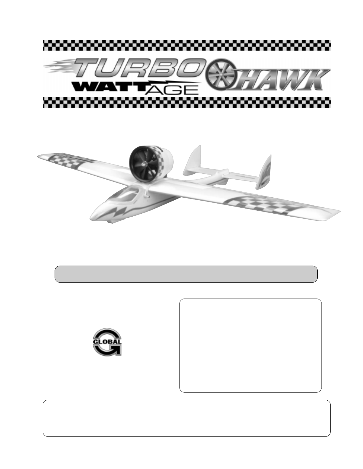
Step 1: Installing the Capacitors & Motor Wires
❑ (1) Impeller Nut
❑ (2) M2 x 4 Machine Screws
❑ (3) Noise-Suppression Capacitors
❑ 220 Grit Sandpaper w/Sanding Block
❑ K&S 30 Watt Soldering Iron
❑ Solder
❑ Carefully solder the three noise-suppression capacitors
to the positive and negative terminals on the back of the
motor. Two capacitors are soldered between the terminals
and the motor can, and one capacitor is soldered between
the two terminals.
Step 2: Installing the Motor & Impeller Assembly
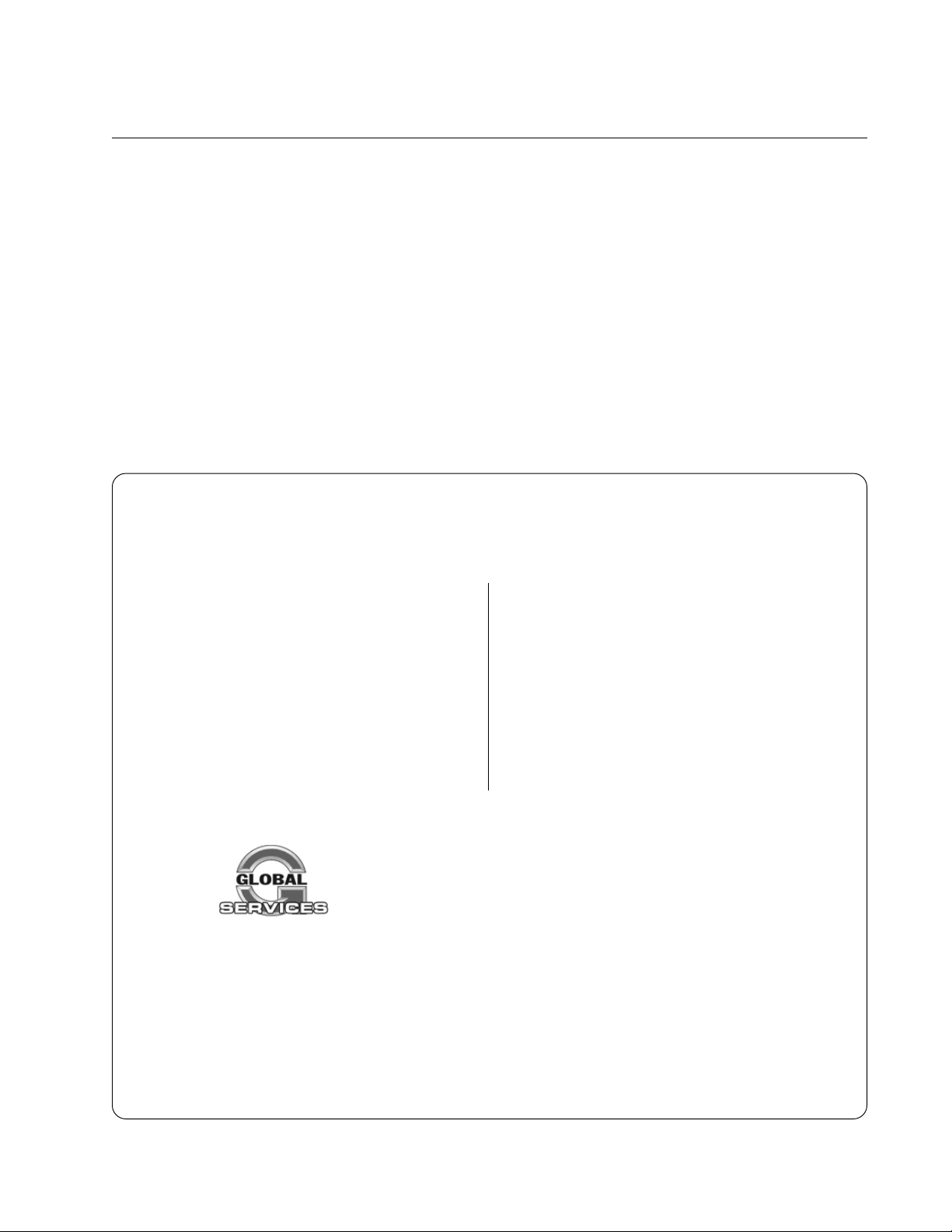
So the solder will stick to the motor can, you should
☞
roughen the side of the can with 220 grit sandpaper first.
❑ Solder two 10" long 16 gauge silicon motor wires (not
included) to the positive and negative terminals on the back
of the motor. Under no circumstances should you attach
the motor wires with slide-on connectors. Use solder!
The terminal with the red dot next to it is the positive
☞
terminal.
IMPORTANT The motor wires must be 10" long to reach
the fuselage and still have some extra left to work with.
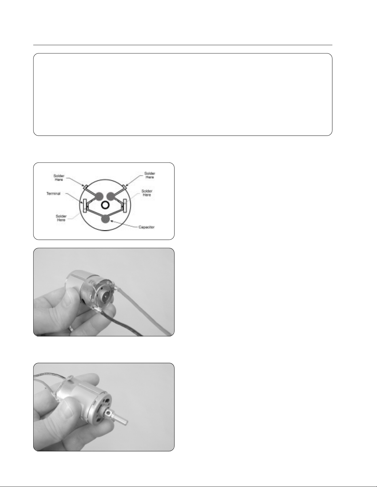
IMPORTANT When installing the threaded shaft adapter in
the next procedure, we strongly suggest applying threadlocker
to the set screw. This will prevent the screw from loosening
during flight.
❑ Slide the threaded shaft adapter onto the motor shaft and
tighten the set screw using a .050 hex wrench. There should
be about a 1/16" gap between the shaft adapter and the motor.
Make sure that the back of the shaft adapter does not
☞
rub against the front of the motor.
8
Visit our website at http://watt-age.globalhobby.com or for Customer Service at http://globalservices.globalhobby.com
Page 9
❑ Slide the motor into the fan shroud and line up the holes
in the front of the motor with the matching holes in the shroud.
❑ Install and tighten the two M2 x 4 machine screws to
secure the motor into place.
We suggest applying threadlocker to the screws before
☞
installing them. This will prevent them from loosening during
flight.
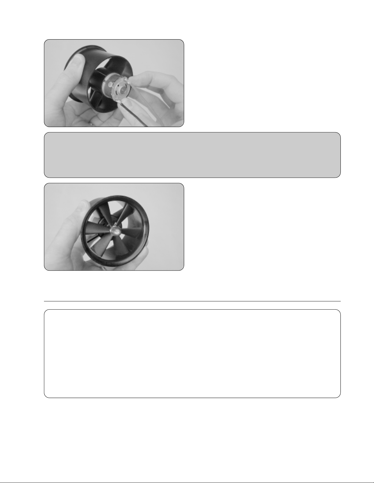
Important Tip: Before the impeller is installed in the next procedure, we recommend that you check the impeller's
balance. Usually our impellers will not need balancing, but it's a good idea to check. We suggest using a propeller
balancer to do this. If the impeller is out of balance, apply a small piece of electrical tape to the back side of the "light
blade" and re-test until you are satisfied that the impeller is balanced. We do not suggest sanding the blades to
balance the impeller because of the chance of blade distortion and/or damage.
❑ Slide the impeller onto the shaft adapter, making sure
that the small sticker on the impeller hub is toward the front
of the shroud. (Remove the sticker after installation.)
❑ Thread the impeller nut into place and tighten it firmly,
using an adjustable wrench.
SECTION 5: WING ASSEMBLY
YOU'LL NEED THE FOLLOWING PARTS FROM THE KIT:
❑ (1) Right & Left Wing Panels
❑ (1) Wing & Stabilizer Reinforcement Board - 8 Parts
❑ (1) Wing Trailing Edge Reinforcement Board
YOU'LL NEED THE FOLLOWING TOOLS AND SUPPLIES:
❑ Kwik Bond 5 Minute Epoxy
❑ Excel Modeling Knife
❑ Ruler
❑ Pencil
❑ 220 Grit Sandpaper w/Sanding Block
Step 1: Joining the Wing Panels
Very carefully push a small piece of wire between the
☞
impeller blades and into the motor (not far in) to prevent the
motor from turning while tightening the impeller nut.
❑ (1) Wing Reinforcement Board - Strip
❑ (2) Plywood Nacelle Mounting Plates
❑ (2) Prebent Aileron Torque Rods
❑ Paper Towels
❑ Rubbing Alcohol
❑ NHP Epoxy Mixing Sticks
❑ NHP Epoxy Mixing Cups
❑ Test-fit the two wing panels together. They should fit together with few or no gaps between the two, and the leading
and trailing edges should line up evenly. If the wing panels don't fit together properly, carefully sand the root ends of each
wing panel straight using 220 grit sandpaper with a sanding block, being careful not to alter the dihedral angle.
Need help or have any questions? Call us at 1-714-963-0329 or send us an Email at service@globalhobby.net
9
Page 10
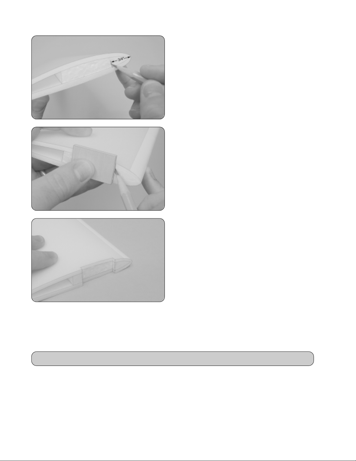
❑ Using a ruler and a pencil, measure back 3/4" from the
leading edge of one wing panel (at the root end) and draw
a vertical mark.
❑ Hold one of the plywood nacelle mounting plates up
against the root end of the wing, making sure that the front of
the plate is even with the mark you drew and that the bottom
of the plate is flush with the bottom of the wing.
❑ When satisfied with the alignment, hold the plate in place
and use a pencil to draw two vertical lines onto the root end of
the wing, using the front and back of the plate as a guide.
❑ Using a modeling knife, carefully cut a 1/8" deep notch in
the root end of the wing panel, using the two lines you drew
as a guide.
When cut properly, the plywood plate should fit firmly into
☞
the notch and the outer surface of the plate should be flush
with the root end of the wing panel.
❑ Repeat the previous procedures to cut a notch in the root end of the second wing panel.
It's important that the notches in each wing panel line up with each other when the wing panels are joined together.
☞
❑ Mix a generous amount of 5 minute epoxy and carefully apply a thin layer to the root ends of both wing panels. Do not
apply epoxy to the inside of the notches that you cut.
Special Note: For maximum wing strength, make sure to cover the entire surface of each root end.
❑ Fit the wing panels back together and realign them. Remove any excess epoxy that squeezes out of the joint using
a paper towel and rubbing alcohol, and hold the wing panels together firmly until the epoxy sets up - about 10 minutes.
Step 2: Installing the Plywood Nacelle Mounting Plate Assembly
❑ Mix a small quantity of 5 minute epoxy and use a thin layer to glue the two plywood plates together, making sure that
the edges of both plates are even with each other. Remove any excess epoxy using a paper towel and rubbing alcohol,
and hold the plates together until the epoxy sets up.
10
Visit our website at http://watt-age.globalhobby.com or for Customer Service at http://globalservices.globalhobby.com
Page 11
❑ After the epoxy fully cures, sand the edges of the nacelle
mounting plate assembly smooth and straight.
❑ Test-fit the nacelle mounting plate into the notch in the
wing. The plate should fit firmly within the notch and the
bottom of the plate should be flush with the bottom surface
of the wing.
IMPORTANT So that the EDF fan unit assembly lines up
properly when it's installed later, it's important that the
mounting plate be aligned properly. Double-check that the
bottom of the mounting plate is perfectly flush with the
bottom surface of the wing.
❑ When satisfied with the fit and alignment, glue the mounting plate into place using a generous amount of 5 minute
epoxy. Remove any excess epoxy using a paper towel and rubbing alcohol, and hold the plate in place until the epoxy sets up.
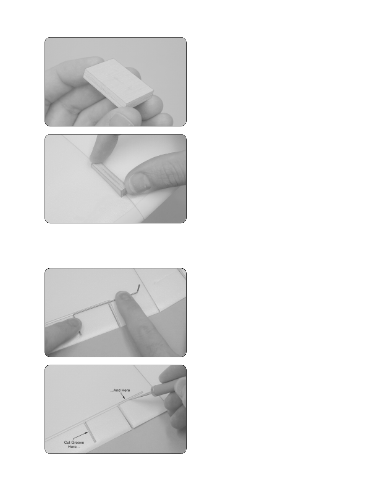
Step 3: Installing the Aileron Torque Rods
❑ Working with one aileron for now, place one torque rod
over the molded hinge line and align it so that the threaded
end of the torque rod is 3/8" out from the centerline of the wing.
IMPORTANT Do this on the top of the wing.
❑ With the torque rod aligned, carefully push down on the
torque rod to make an impression of its location on both the
wing and the aileron.
❑ Using a modeling knife and a ruler, carefully cut a very
shallow groove along the impression the torque rod made.
Do not cut into or through the aileron hinge line.
IMPORTANT Cut the groove just shallow enough so that the
torque rod will fit down into the groove and be flush with the top
of both the wing and the aileron. The torque rod should lay in
the molded hinge line.
Need help or have any questions? Call us at 1-714-963-0329 or send us an Email at service@globalhobby.net
11
Page 12

❑ Test-fit the torque rod into the groove. Because the torque
rod is actuated from the bottom of the wing, you will need to
carefully push the threaded end of the torque rod through the
top of the wing, as shown.
❑ When satisfied with the fit, mix a small quantity of 5 minute
epoxy and use it to glue the torque rod into ONLY the aileron.
Remove any excess epoxy using a paper towel and rubbing
alcohol, and allow the epoxy to set up before proceeding.
Important Tip: Do not glue the torque rod to the wing or to the leading edge of the aileron. If you do this, the aileron
will be glued solid and won't be able to pivot up and down.
❑ After the epoxy has set up, apply one piece of aileron
reinforcement board onto the aileron to secure the torque
rod firmly into place.
❑ Repeat the previous procedures to install the second
aileron torque on the opposite half of the wing.
Step 4: Installing the Wing Reinforcement Board
❑ Using a modeling knife and a ruler, carefully cut the
angle on the trailing edge of the wing straight.
IMPORTANT Make the cut from the inside tip of one aileron
cutout to the inside tip of the opposite aileron cutout.
❑ Carefully fold the wing trailing edge reinforcement board
lengthwise, 1-3/8" from the end.
12
Visit our website at http://watt-age.globalhobby.com or for Customer Service at http://globalservices.globalhobby.com
Page 13

❑ Remove the reinforcement board from its protective
backing and carefully adhere the reinforcement board to the
trailing edge of the wing at the center section.
IMPORTANT The longer portion of the reinforcement board
should be on the top of the wing so that it covers (and holds in
place) the aileron torque rods. Make sure that the torque
rods are pushed down into the grooves you cut.
❑ Carefully apply the large piece of reinforcement board
to the bottom of the wing, making sure that it's centered
over the wing's centerline and that the back edge of the
reinforcement board is about 1/4" in front of the torque rods.
It's very important to the integrity of the wing that the
☞
reinforcement board be adhered to the wing along its entire
surface.
❑ Carefully apply the reinforcement board strip to the top
of the wing, making sure that it's centered over the wing's
centerline and that the back edge of the reinforcement board
is 1/4" in front of the trailing edge reinforcement board.
It's very important to the integrity of the wing that the
☞
reinforcement board be adhered to the wing along its entire
surface.
❑ After applying the pieces of wing reinforcement board, carefully pivot the ailerons up and down several times to free
up the torque rods. They should not stick to the reinforcement board.
❑ Each aileron should pivot up and down about 3/8". If
they don't you'll need to use a modeling knife to cut a groove
at the base of each torque rod to allow room for the torque
rods to pivot back and forth.
Need help or have any questions? Call us at 1-714-963-0329 or send us an Email at service@globalhobby.net
13
Page 14

SECTION 6: WING MOUNTING
YOU'LL NEED THE FOLLOWING PARTS FROM THE KIT:
❑ (1) Fuselage
❑ (1) 2-3/4" Aluminum Tube
❑ (1) 2-3/8" Aluminum Tube
YOU'LL NEED THE FOLLOWING TOOLS AND SUPPLIES:
❑ Kwik Bond 5 Minute Epoxy
❑ Excel Modeling Knife
❑ 220 Grit Sandpaper w/Sanding Block
❑ Paper Towels
Step 1: Installing the Aluminum Wing Hold-Down Tubes
❑ Using a modeling knife , carefully cut out the wing saddle
along the molded scribe lines.
☞
it's easier to make several shallow cuts. It also helps to use a
very sharp knife blade.
❑ (4) Nylon Bushings
❑ (2) Rubber Bands
❑ Rubbing Alcohol
❑ NHP Epoxy Mixing Sticks
❑ NHP Epoxy Mixing Cups
Instead of trying to cut through the plastic in one pass,
14
❑ Using a modeling knife, carefully cut away the material
from inside each of the four molded circles in front of and
behind the wing saddle.
Don't cut away the material from the molded circle above
☞
the molded switch mount.
❑ Test-fit the nylon sleeves and aluminum tubes into the
fuselage, making sure that both tubes are centered.
IMPORTANT The longer of the two aluminum tubes should
be installed at the front of the wing saddle.
Visit our website at http://watt-age.globalhobby.com or for Customer Service at http://globalservices.globalhobby.com
Page 15

❑ When satisfied with the alignment, remove the aluminum tubes and the nylon sleeves.
❑ Using 220 grit sandpaper, lightly roughen the gluing surfaces of the sleeves, aluminum tubes and inside the fuselage
around the mounting holes.
Special Tip: Sanding the gluing surfaces will roughen the smooth plastic and aluminum. This is important because
it will allow the epoxy to stick much better. Do not omit this procedure.
❑ Using a small quantity of 5 minute epoxy, glue the nylon sleeves and aluminum tubes to the fuselage, making sure that
the tubes are centered. Remove any excess epoxy using a paper towel and rubbing alcohol, and allow the epoxy to cure
before proceeding.
Special Tip: For a cleaner installation, we applied the epoxy from the inside of the fuselage.
Step 2: Mounting the Wing
❑ Set the wing into the wing saddle and align it. The
centerline of the wing (the glue joint) should line up with the
fuselage mold lines at the front and back of the wing saddle.
❑ When satisfied with the alignment, hold the wing securely
into place using two rubber bands. When installing the wing
for flight, use four rubber bands to hold it in place.
SECTION 7: STABILIZER INSTALLATION
YOU'LL NEED THE FOLLOWING PARTS FROM THE KIT:
❑ (1) Horizontal Stabilizer
❑ (2) Vertical Stabilizers
YOU'LL NEED THE FOLLOWING TOOLS AND SUPPLIES:
❑ Kwik Bond 5 Minute Epoxy
❑ # 0 Phillips Head Screwdriver
❑ Excel Modeling Knife
❑ Electric or Hand Drill
❑ 1/16" Drill Bit
❑ Ruler
❑ Pencil
Step 1: Installing the Vertical Stabilizers
Leave the wing in position for now. It will need to be
☞
installed to line up the flying surfaces in the next section.
❑ (1) Wing & Stabilizer Reinforcement Board - 8 Parts
❑ (8) M1.4 x 4 Wood Screws
❑ 220 Grit Sandpaper w/Sanding Block
❑ Masking Tape
❑ Paper Towels
❑ Rubbing Alcohol
❑ NHP Epoxy Mixing Sticks
❑ NHP Epoxy Mixing Cups
❑ Using 220 grit sandpaper with a sanding block, lightly sand the edges of the horizontal and vertical stabilizers to
remove any flashing. Be careful not to alter the 90º angle on the ends of the horizontal stabilizer.
Need help or have any questions? Call us at 1-714-963-0329 or send us an Email at service@globalhobby.net
15
Page 16

❑ Using a modeling knife and a ruler, carefully cut 1/16" of
material off of each end of the elevator.
Cutting the ends of the elevator shorter will prevent the
☞
elevator from hitting the side of the vertical stabilizers when
they are glued into place.
❑ Carefully align one vertical stabilizer to one end of the
horizontal stabilizer. When aligned properly, the leading and
trailing edges of the horizontal stabilizer should be lined up
with the two molded marks in the vertical stabilizer, and the
vertical stabilizer should be perpendicular to the horizontal
stabilizer when viewed from the front.
The horizontal stabilizer is symmetrical, so it doesn't
☞
matter which direction the top of the vertical stabilizer faces.
❑ When satisfied with the alignment, glue the vertical stabilizer to the end of the horizontal stabilizer using a thin layer
of 5 minute epoxy. Remove any excess epoxy using a paper towel and rubbing alcohol, and hold the stabilizer in place and
aligned until the epoxy sets up.
WARNING Don't apply epoxy to the end of the elevator. You don't want to glue the elevator to the vertical stabilizer.
❑ Repeat the previous procedures to install the second vertical stabilizer to the other end of the horizontal stabilizer.
Step 2: Installing the Stabilizer Mounting Board
❑ Remove the two tapered pieces of stabilizer mounting
board from the protective backing.
❑ Apply one piece of mounting board to the top and one
piece to the bottom of the horizontal stabilizer assembly. The
back edge of each piece should be even with the front of the
molded hinge line, and the edges of the mounting board should
be flush with the edges of the molded mounting platform.
Step 3: Installing the Horizontal Stabilizer Assembly
Special Tip: Do not epoxy the stabilizer to the fuselage. Because of the plastic that the fuselage is molded from,
even roughening the surface will not allow the epoxy to adhere strong enough to hold the stabilizer securely. Screwing
the stabilizer into place, while different from other models, actually works very well and results in a very secure joint.
16
Visit our website at http://watt-age.globalhobby.com or for Customer Service at http://globalservices.globalhobby.com
Page 17

❑ Cut out the two horizontal stabilizer mounting slots in the
back of the fuselage. The easiest way to do this is to first
carefully sand the outside of the slots until the edges of the
flanges begin to show through. At this point the plastic will be
thin enough to allow you to easily cut out the remaining plastic
with a modeling knife.
You will need to cut a slot in the back of the fuselage so
☞
that the stabilizer can be slid into place.
IMPORTANT Do not cut out the mounting slot in the top of the fuselage.
❑ Using a 1/16" drill bit, carefully drill eight holes through
the horizontal stabilizer mounting flanges. Drill two holes
through the top and bottom of each of the flanges. The
rear holes should be 5/16" in front of the back of the fuselage
and the front holes should be 1-3/4" in front of the back of
the fuselage.
Drill the holes nearer the fuselage sides. This will ensure
☞
that the screws don't miss the stabilizer mounting board when
you install them later.
❑ Using a modeling knife, carefully trim away the plastic burrs left from drilling the holes.
❑ Slide the horizontal stabilizer assembly into place. Push the stabilizer as far forward as possible and align the outer
edges of the reinforcement board with the outer edges of the mounting flanges.
❑ With the wing mounted to the fuselage and the stabilizer
in place, look carefully from the front of the fuselage at both
the wing and the stabilizer. When aligned properly, the
stabilizer should be level with the wing. If it is not level, use a
modeling knife and/or 220 grit sandpaper and adjust the
mounting flanges until the correct alignment is achieved.
It may be necessary to slide thin shims between the
☞
B=B-1
flanges and the stabilizer to align it properly to the wing.
❑ Now check to make sure that the tips of the stabilizer are
equal distances from the tips of the wing. Use a ruler and
measure from one wing tip to the stabilizer tip on the same
side. Do this for both sides. When the stabilizer is aligned
properly, both of these measurements should be the same.
A=A-1
Need help or have any questions? Call us at 1-714-963-0329 or send us an Email at service@globalhobby.net
17
Page 18

❑ When satisfied with the alignment, use a couple of pieces of masking tape to hold the stabilizer in place and aligned.
❑ Using the tip of your modeling knife, make very small
pilot holes in the stabilizer mounting board using the holes
you drilled in the mounting flanges as a guide.
❑ Install and lightly tighten the eight M1.4 x 4 wood screws
to hold the stabilizer firmly in place.
Be careful not to overtighten the screws or the mounting
☞
board will strip out.
SECTION 8: CONTROL SYSTEMS INSTALLATION
YOU'LL NEED THE FOLLOWING PARTS FROM THE KIT:
❑ (1) 15-3/4" Threaded Wire
❑ (2) 5-7/8" Threaded Wires
❑ (1) Nylon Control Horn
❑ (1) Nylon Control Horn Backplate
YOU'LL NEED THE FOLLOWING TOOLS AND SUPPLIES:
❑ # 0 Phillips Head Screwdriver
❑ Magnum Z-Bend Pliers
❑ Wire Cutters
❑ Excel Modeling Knife
❑ (3) Nylon Clevises
❑ (2) Nylon Adjustable Control Horns
❑ (1) Elevator Servo Mounting Board
❑ (1) Foam Elevator Servo Tray
❑ Electric or Hand Drill
❑ 1/16" Drill Bit
❑ Ruler
❑ Pencil
Step 1: Installing the Elevator Servo Tray
❑ Carefully bend the sides of the elevator servo mounting
board up at a 90º angle at the two precut scribe lines.
When bending the board, bend it up toward the board
☞
side. Don't bend it down toward the protective backing side.
❑ Punch out the die-cut piece of foam from the middle of the foam elevator servo tray.
❑ Remove the protective backing from the servo mounting board and place the foam servo tray onto the board, making
sure that the servo tray is lined up with the edges of the mounting board.
The mounting board is shaped at an angle just like the foam servo tray. Make sure the two match.
☞
18
Visit our website at http://watt-age.globalhobby.com or for Customer Service at http://globalservices.globalhobby.com
Page 19

❑ Press the mounting board down firmly to secure the foam
servo tray firmly into place.
❑ Bend down both of the outer and inner tabs on the
mounting board and press them into place against the foam
servo tray.
IMPORTANT Before installing the servo tray assembly in the next procedure, note that the servo tray is angled to match
the sides of the fuselage. The wider end of the servo tray should be toward the front of the fuselage.
❑ Install the servo tray assembly into the fuselage. To align
the assembly properly, the back edges of the mounting board
should be pushed up against the wing mounting tube, and the
top of the mounting board should be pushed up against the
bottom of the wing saddle.
❑ When satisfied with the alignment, press the sides of the
mounting board firmly against the fuselage sides to secure
the assembly into place.
Step 2: Installing the Elevator Servo & Pushrod Assembly
❑ Install the rubber grommets and brass collets onto the
elevator servo mounting lugs.
When installing the collets, make sure that the flanges
☞
are toward the bottom of the mounting lugs.
❑ Test-fit the servo into the servo tray. The servo should
be pushed to one side of the tray so that the servo arm will be
toward the middle of the fuselage. If the servo is too large to
fit, use a modeling knife to enlarge the cutout in the servo tray
to accommodate the servo.
The servo output shaft should face toward the front of
☞
the fuselage.
❑ Mount the servo using the servo mounting screws provided with your servo. To make it easier to install the screws, use
the tip of your modeling knife to make small pilot holes in the servo mounting board.
Need help or have any questions? Call us at 1-714-963-0329 or send us an Email at service@globalhobby.net
19
Page 20

❑ Using a modeling knife, cut a thin slot through the elevator,
in the middle of the molded control horn mounting area.
❑ Push the end of the control horn through the slot so that
the tip of the control horn is toward the bottom of the elevator.
❑ Making sure that the flat portion of the control horn
backplate faces away from the elevator, push the backplate
over the end of the control horn until you hear it "click" firmly
into place.
❑ Plug the elevator servo lead into its proper slot in your receiver. Plug the ESC lead into your receiver and plug
the flight battery into your ESC. Turn on your radio system and center the servo using the elevator trim lever on
your transmitter.
❑ Thread one nylon clevis onto the 15-3/4" long threaded pushrod wire.
Thread the clevis on far enough to leave room for adjustments later.
☞
❑ Slide the plain end of the pushrod wire through the hole
in the back of the fuselage, then carefully snap the clevis into
the elevator control horn.
IMPORTANT Make sure that the clevis snaps completely
down into the control horn.
❑ Place a "single arm" servo horn onto the elevator servo, making sure that the servo horn is centered and points
toward the middle of the fuselage. The arm should have at least two holes in it.
❑ With both the servo horn and the elevator centered, use
a pencil to draw a mark on the pushrod wire where it crosses
the hole that is 1/4" out from the center of the servo horn.
If you're using Cirrus CS-10 servos this will be the first
☞
hole in the servo arm.
❑ Using Magnum Z-Bend Pliers, make a Z-Bend in the pushrod wire at the mark you drew and use wire cutters to
remove the excess wire.
Special Tip: It's easier to properly make the Z-Bend if you remove the pushrod wire first.
❑ Remove the servo horn. Using a 1/16" drill bit, enlarge the hole in the servo arm that is 1/4" out from the center of the
servo horn.
20
Visit our website at http://watt-age.globalhobby.com or for Customer Service at http://globalservices.globalhobby.com
Page 21

❑ Attach the servo horn to the Z-Bend, then attach the servo
horn to the servo, making sure it's centered.
❑ Install and tighten the servo horn retaining screw, provided
with your servo, to secure the servo horn into place.
You should cut away the excess length of servo arm
☞
so it doesn't interfere with the aileron linkage when the wing
is installed.
❑ With the servo horn centered, double-check that the elevator is still centered. If it is out of adjustment, remove the
clevis and readjust it until you are satisfied with the alignment. Unplug and turn off your radio system.
Step 3: Installing the Aileron Servo & Linkage Assembly
❑ Install the rubber grommets and brass collets onto your aileron servo mounting lugs.
❑ Using a ruler and a pencil, measure forward 3-3/4" from the trailing edge of the wing (at the centerline, on the
bottom) and draw a mark at this location. Do this on the bottom of the wing.
❑ Place your aileron servo on the bottom of the wing,
aligning the front of the case with the mark you drew.
IMPORTANT Align the front of the case with the mark you
drew, not with the front of the mounting lug.
❑ Center the servo over the wing's centerline and trace
around the base of the servo using a pencil.
❑ Using a modeling knife, carefully cut out the wing to accommodate your servo. Don't cut the hole too large, though.
The servo should fit tightly.
WARNING For the servo mounting lugs to fit down against the wing, you'll need to remove as much of the foam as
possible from the bottom of the servo cutout. Be careful not to cut through the top of the wing!
❑ Push the servo into the cutout making sure that the servo
output shaft is toward the leading edge of the wing.
You will need to cut a notch in the side of the cutout for
☞
the servo wire to exit the bottom of the wing.
❑ Install the servo using the mounting screws provided with your servo. To make it easier to thread the servo mounting
screws through the wing reinforcement board, make small pilot holes first, using the tip of your modeling knife.
Need help or have any questions? Call us at 1-714-963-0329 or send us an Email at service@globalhobby.net
21
Page 22

❑ Carefully thread the two nylon adjustable control horns
onto the aileron torque rods. The openings in the control horns
should face up and toward the leading edge of the wing, and
the top of the control horns should be even with the top of the
torque rods.
IMPORTANT So both ailerons have the same amount of
control throw, make sure that both control horns are even with
each other.
❑ Plug the aileron servo lead into its proper slot in your receiver. Plug the ESC lead into your receiver and plug the flight
battery into your ESC . Turn on your radio system and center the servo using the aileron trim lever on your transmitter.
❑ Thread one nylon clevis onto each of the two 5-7/8" long threaded pushrod wires. Thread the clevises on far enough
to leave room for adjustments later.
❑ Carefully snap each of the clevises into the adjustable
control horns.
Again, make sure to snap the clevises completely into
☞
the control horns.
❑ Place a "dual arm" servo horn onto the aileron servo, making sure that the servo horn is centered.
Each arm should have at least two holes in it.
☞
❑ With the servo horn and both ailerons centered, use a pencil to draw a mark on each pushrod wire where it crosses the
hole that is 1/4" out from the center of the servo horn.
If you're using CS-10 servos, this is the first hole out from the center of the servo horn.
☞
❑ Make a Z-Bend in each pushrod wire at the mark you drew, then use wire cutters to remove the excess wire.
❑ Attach the servo horn to the Z-Bends, then attach the
servo horn to the servo, making sure that it's centered.
You will have to enlarge the holes in the servo arms using
☞
a 1/16" drill bit so that you can attach the pushrods.
❑ Install and tighten the servo horn retaining screw, provided
with your servo, to secure the servo horn into place.
❑ Double-check that both ailerons are still centered. If they are out of adjustment, remove the clevises and readjust
them until you are satisfied with the alignment. Unplug and turn off your radio system.
22
Visit our website at http://watt-age.globalhobby.com or for Customer Service at http://globalservices.globalhobby.com
Page 23

SECTION 9: EDF FAN UNIT INSTALLATION
YOU'LL NEED THE FOLLOWING PARTS FROM THE KIT:
❑ (1) EDF Nacelle
YOU'LL NEED THE FOLLOWING TOOLS AND SUPPLIES:
❑ Kwik Bond 5 Minute Epoxy
❑ Excel Modeling Knife
❑ Scissors
❑ Ruler
❑ 220 Grit Sandpaper w/Sanding Block
Step 1: Installing the EDF Fan Unit
❑ Paper Towels
❑ Rubbing Alcohol
❑ NHP Epoxy Mixing Sticks
❑ NHP Epoxy Mixing Cups
❑ Using a modeling knife and/or a pair of scissors, cut away
and remove the material from the back of the EDF nacelle.
IMPORTANT For proper airflow, make sure to remove any
molded radius from the back edge of the nacelle.
❑ Using 220 grit sandpaper with a sanding block, sand the
back edge of the nacelle smooth and straight.
❑ Test-fit the EDF fan unit into the nacelle. The back edge
of the fan unit fits into the molded "step" in the back of the
nacelle. You will have to push the fan unit down into place
firmly to get it to seat properly in the molded step.
❑ When you have the fan unit seated properly in the
nacelle, rotate the fan unit so that any one of the stator blades
(not fan blades, the big blades behind the fan) is lined up with
the precut mounting slot in the bottom of the nacelle.
❑ Using a pencil, outline the precut mounting slot in the bottom of the nacelle onto the surface of the EDF fan unit, then
remove the fan unit from the nacelle.
❑ Using 220 grit sandpaper with a sanding block, lightly
sand the fan unit at the outline you drew.
IMPORTANT Do not omit this procedure. You must roughen
this area of the fan unit so that the epoxy will stick better when
the assembly is glued to the wing.
❑ Now sand the gluing surfaces of the fan unit and the
nacelle. This includes the back of the fan unit and the molded
"step" in the nacelle. The back of the front edge of the fan unit
and the inside front area of the nacelle should be sanded, too.
Need help or have any questions? Call us at 1-714-963-0329 or send us an Email at service@globalhobby.net
23
Page 24

❑ Mix a small quantity of 5 minute epoxy and apply a thin layer to the "step" inside the nacelle and a thin layer to the back
edge of the front of the fan unit.
❑ Slide the fan unit back into place, making sure that you rotate the fan unit so that the mounting area that you sanded
is lined up with the precut mounting slot in the bottom of the nacelle. When satisfied with the alignment, remove any
excess epoxy using a paper towel and rubbing alcohol, and allow the epoxy to fully cure.
❑ After the epoxy has fully cured, use a pair of scissors to
carefully cut away the excess portion of the nacelle flush with
the front edge of the fan unit.
Step 2: Mounting the Engine Nacelle Assembly
❑ Test-fit the engine nacelle assembly onto the wing by
sliding the precut slot in the bottom of the nacelle over the
plywood mounting post in the wing. To align the assembly
properly, the nacelle should be perpendicular to the top of
the wing (when viewed from the front) and the nacelle should
be pushed down firmly so that the fan unit sits flat on top of
the plywood mounting post. This will ensure the correct
thrust angle.
❑ When satisfied with the fit and alignment, glue the engine nacelle assembly into place using a generous amount of 5
minute epoxy. Remove any excess epoxy using a paper towel and rubbing alcohol, and hold the assembly firmly in place
and aligned until the epoxy completely sets up.
Special Tip: After the epoxy sets up, we strongly suggest allowing it to completely cure (about 1 hour) before
handling the wing. This will ensure that the engine nacelle assembly does not get knocked out of alignment.
❑ Using a modeling knife, carefully cut two small holes
through the wing, behind the engine nacelle assembly, to run
the motor wires down through the wing.
24
Make sure to cut the holes far enough back so that they
☞
don't hit your aileron servo.
Visit our website at http://watt-age.globalhobby.com or for Customer Service at http://globalservices.globalhobby.com
Page 25

SECTION 10: FINAL ASSEMBLY
YOU'LL NEED THE FOLLOWING PARTS FROM THE KIT:
❑ (1) Clear Canopy
❑ (1) Nose Cone
❑ (1) Plastic Switch Mount - Optional
❑ (2) M2 x 5 Wood Screws - Optional
YOU'LL NEED THE FOLLOWING TOOLS AND SUPPLIES:
❑ Kwik Bond 5 Minute Epoxy
❑ Wire Cutters
❑ Excel Modeling Knife
❑ Scissors
❑ 220 Grit Sandpaper w/Sanding Block
❑ Paper Towels
❑ (1) Velcro
❑ (1) Double-Sided Foam Tape
❑ (1) Decal Set
❑ Rubbing Alcohol
❑ NHP Epoxy Mixing Sticks
❑ NHP Epoxy Mixing Cups
❑ Solder
❑ Heat-Shrink Tubing (Assorted Sizes)
Step 1: Installing the Nose Cone
❑ Using a pair of scissors, cut out the nose cone along its base, making sure to completely remove the molded radius.
❑ Using 220 grit sandpaper with a sanding block, sand the back of the nose cone smooth and straight.
®
Strip
❑ Using a thin layer of 5 minute epoxy, glue the nose cone
onto the fuselage. Remove any excess epoxy using a paper
towel and rubbing alcohol, and hold the nose cone in place
until the epoxy sets up.
IMPORTANT Remember to roughen the gluing surfaces
with 220 grit sandpaper before gluing the nose cone into place.
Step 2: Installing the Canopy
❑ Using a pair of scissors, carefully cut out the clear canopy along the molded scribe lines.
IMPORTANT Be careful not to cut off the mounting tabs on the front and sides of the canopy!
❑ Using 220 grit sandpaper with a sanding block, sand the edges of the canopy smooth and straight.
❑ Set the canopy into the molded recess in the fuselage
and mark the locations of the three mounting tabs onto the
fuselage using a pencil.
❑ Remove the canopy and use a sharp modeling knife to
cut thin slots through the fuselage for the tabs to slide into.
IMPORTANT Cut the slots on the inside edge of the molded
recess and no larger than the size of the mounting tabs.
Need help or have any questions? Call us at 1-714-963-0329 or send us an Email at service@globalhobby.net
25
Page 26

❑ Install the canopy by carefully pushing the mounting tabs
into the slots that you cut. Push the canopy down firmly to
secure it into place.
Step 3: Installing the Receiver
The locations of the radio equipment shown in the next few steps is only approximate. This is how our test airplanes
were set up. The locations of your radio equipment could differ and should be dependent on what type of equipment
you use and where you balance your airplane. Balancing will be done in the next section.
❑ Plug the elevator servo lead into its proper slot in the receiver.
❑ Uncoil the receiver antenna and feed it through the inside of the fuselage and out the back. As an alternative, you
could drill a small hole in the side of the fuselage and run the antenna out through that, then secure it to the back of the
fuselage using a small piece of clear decal or tape.
Important Tip: If you run the antenna through the inside of the fuselage, make sure that the antenna is not wrapped
around or otherwise touching the elevator pushrod wire, or radio interference could result.
❑ Mount the receiver to the fuselage floor, in front of the
servo tray, using a small piece of double-sided foam tape.
We wound up the excess antenna onto an antenna
☞
bobbin and secured the bobbin to the side of the fuselage
using a small piece of double-sided foam tape.
Step 4: Installing the Electronic Speed Control
Important Tip: So that you can install and remove the wing you will need to solder a connector to the motor wires and
to your ESC. To prevent current loss, we strongly suggest you use a Dean's Ultra-Plug for this connection.
Even More Important Tip: To minimize current loss, it is imperative that you remove the stock Tamiya connector
likely preinstalled on your ESC and flight battery, and replace it with a high-quality connector, such as a Dean's UltraPlug. Failure to do this can cause a loss of power and result in a poor flying airplane.
26
Visit our website at http://watt-age.globalhobby.com or for Customer Service at http://globalservices.globalhobby.com
Page 27

❑ Carefully solder high-quality connectors to the positive and negative motor wires onto your ESC and onto your motor
wires, being careful that the polarity is correct. This will allow you to unplug the motor wires from the ESC so that you can
easily remove and install the wing.
❑ Remove the stock Tamiya battery connector likely preinstalled on your ESC and solder on a high-quality connector.
Important Tip: Again, to minimize current loss, it is imperative that you remove the stock Tamiya connector likely
preinstalled on your ESC, and replace it with a high-quality connector, such as a Dean's Ultra-Plug. Failure to do this
can cause a loss of power and result in a poor flying airplane.
❑ Mount the ESC to the fuselage side, under the forward
wing hold-down tube, using a piece of double-sided foam tape.
IMPORTANT If your ESC features a micro switch, we
suggest mounting it into the side of the fuselage using the
plastic switch mount and two M2 x 5 wood screws provided.
Step 5: Installing the Flight Battery
❑ Mount the flight battery to the fuselage floor using a piece
of Velcro
☞
the flight battery. This holds the flight battery more than
securely enough, yet allows the flight battery to be removed
easier. This is better than using a long strip of Velcro
®
.
We used a small piece of Velcro® only at the back end of
®
.
IMPORTANT The location of the flight battery shown above is only approximate. You may need to move it fore or aft to
balance the airplane when that is done in the next section.
❑ Using a modeling knife, carefully cut out the front of the
molded air-intake scoop on the bottom of the fuselage.
IMPORTANT Do not omit this procedure. This will allow air
to enter the fuselage and cool your flight battery and ESC.
The air will exit through the hole in the back of the fuselage.
Need help or have any questions? Call us at 1-714-963-0329 or send us an Email at service@globalhobby.net
27
Page 28

Step 6: Applying the Decals
❑ Working with one decal at a time, use a pair of scissors to carefully cut out the decal along its outer edges.
❑ Remove the protective backing from the decal and apply the decal to the airplane. (Use the box cover photos to
position the decals.) Lightly rub the decal with a soft cloth to remove any trapped air from beneath it.
If any air bubbles form in the decal you can "prick" the bubble with a straight pin to release the air.
☞
❑ Repeat the steps above to apply the remaining decals. Rub each decal down thoroughly to adhere it into place.
SECTION 11: BALANCING THE TURBO HAWK EDF
YOU'LL NEED THE FOLLOWING TOOLS AND SUPPLIES:
❑ Ruler
❑ Pencil
IMPORTANT It is critical that your airplane be balanced correctly. Improper balance will cause your airplane to lose
control and crash!
Center of Gravity Location:
1-1/2" to 1-3/4" back from the leading edge of the wing, measured at the fuselage sides.
WARNING This is the recommended C.G. range. For test-flying we suggest you start with the C.G. in the middle of the
range, then move it farther back as you become familiar with the flying characteristics of the airplane. It is not
recommended that the C.G. be located any farther back than 1-3/4".
IMPORTANT As you move the C.G. farther aft, the airplane will become more responsive, especially in pitch. Do not start
to move the C.G. back until you are comfortable with the flight characteristics of the airplane.
Balance the Turbo Hawk EDF with the flight battery installed.
☞
❑ Measure and draw two marks on the bottom of the wing, 1-5/8" back from the leading edge, measured at the
fuselage sides.
❑ With the airplane right-side up, place your fingers on the marks, and carefully lift the airplane. If the nose of the
airplane falls, the airplane is nose heavy. To correct this, move the flight battery back far enough to bring the airplane into
balance. If the tail of the airplane falls, the airplane is tail heavy. To correct this, move the flight battery forward enough to
bring the airplane into balance. When balanced correctly, the airplane should sit level or slightly nose down when you lift
it up with your fingers at the C.G. location. In some cases, it may be necessary to move your ESC and/or receiver to make
the airplane balance properly.
Once you have flown and become familiar with the flight characteristics of the airplane, the C.G. can be moved forward
☞
or aft up to 1/8" in each direction to change the flight performance. Moving the C.G. back will cause the airplane to be more
responsive, but less stable. Moving the C.G. forward will cause the airplane to be less responsive, but more stable.
Do not fly the airplane beyond the recommended balance range or an uncontrollable crash could result!
28
Visit our website at http://watt-age.globalhobby.com or for Customer Service at http://globalservices.globalhobby.com
Page 29

SECTION 12: CONTROL THROWS
We recommend setting up the Turbo Hawk EDF using the control throws listed below. These control throws are suggested
for initial test-flying because they will allow the airplane to fly smoother and make it easier to control.
TEST-FLYING
Ailerons: 3/16" Up and Down
Elevator: 3/16" Up and Down
When measuring the control throws, measure from the widest point of the control surfaces.
☞
Once you're familiar with the flight characteristics of the airplane, you might want to increase the control throws to the sportflying settings listed below. These control throws will make the airplane more responsive and allow you to do basic
aerobatics with ease.
SPORT-FLYING
Ailerons: 1/4" Up and Down
Elevator: 1/4" Up and Down
Important Note: We do not suggest increasing the control throws beyond the recommended Sport-Flying settings.
Higher control throws will cause the airplane to be extremely control-sensitive and result in a possible crash if you are
not careful.
SECTION 13: PREFLIGHT CHECK & SAFETY
●
Check the operation of the throttle. To do this, do the following:
A) Plug the flight battery into the ESC and turn on the radio system.
WARNING Do not turn the receiver on unless the transmitter is turned on first. Always turn the transmitter on first.
Never allow hands or clothing to get in the way of the impeller when the radio is turned on. Sudden unwanted radio
signals, or turning the radio on with the throttle stick set at full throttle, can turn the motor on unintentionally. Always
make sure that the throttle control stick is set to idle before turning on the transmitter.
B) When the throttle control stick is at the idle position, the motor should be off. Moving the stick forward
should turn on the motor. Gradually moving the stick to the full forward position should result in the motor running at
full power.
Some ESCs will give you more proportional control than others. Your ESC may also have a manual control
☞
adjustment screw that must be adjusted prior to using the ESC. (Refer to your ESC's operating guide for further
information.)
●
Cycle the flight battery three times. When NiMH or NiCD batteries are new they need to be used 2-3 times before
they will produce their top voltage and duration. To cycle them, simply charge the battery and then run the motor (at
low speed to prevent damaging it) until the motor stops. Allow the battery and motor to cool, then repeat this
procedure two more times.
Continued on Next Page
Need help or have any questions? Call us at 1-714-963-0329 or send us an Email at service@globalhobby.net
29
Page 30

Preflight Check & Safety, Continued....
●
Check the condition of the transmitter batteries. They should be fully charged.
●
Check every bolt and every glue joint in the airplane to ensure that everything is tight and well-bonded.
●
Double-check that all of the control horns are tight.
●
Double-check the balance of the airplane. Do this with the flight battery installed.
●
Check the control surfaces. They should all move in the correct direction and not bind.
●
If your radio transmitter is equipped with dual rate switches, double-check that they are on the low-rate setting for
your first few flights.
●
Check to ensure that all of the control surfaces are moving the proper amount in both low and high rate settings.
●
Check the receiver antenna. It should be fully extended and not coiled up inside the fuselage. The only exception
to this is if the excess antenna is properly wound around an antenna bobbin.
The following are our general guidelines for your safety and the safety of others. Please read and understand
these safety guidelines before going out to the flying field for the first time.
●
Do not test-fly your model for the first time without first having it safety-checked by an experienced modeler.
●
Do not fly your model higher than approximately 400 feet within 3 miles of an airport without having an observer with
you. The observer should tell you about any full-size aircraft in your vicinity and you should always give the right-ofway to full-scale aircraft.
●
When flying at a flying field with established rules, you should abide by those rules. You should not deliberately fly
your model in a reckless and/or dangerous manner.
●
While flying, you should not deliberately fly behind the flight line. If your model should inadvertently fly behind the
flight line, you should change course immediately.
●
You should complete a successful range check of your radio equipment prior to each new day of flying, or prior to the
first flight of a new or repaired model.
●
You should perform your initial turn after take- off away from the flightline and/or spectator area.
●
You should not knowingly operate your R/C radio system within 3 miles of a preexisting model club flying field
without a frequency sharing agreement with that club.
30
Visit our website at http://watt-age.globalhobby.com or for Customer Service at http://globalservices.globalhobby.com
Page 31

SECTION 14: FLYING THE TURBO HAWK EDF
READ THIS BEFORE FLYING YOUR TURBO HAWK EDF FOR THE FIRST TIME
Before flying your Turbo Hawk EDF for the first time, please refer back to page # 5 and re-read the special tips we've
provided you. All of these tips are important, but the most important tips are the fourth one about topping off your flight
battery before every flight and the ninth one about getting used to the fact that this is not a propeller-driven aircraft, so
it will behave differently in the air.
Hand-Launching
Hand-Launching should always be done into the wind. To hand-launch the airplane, gently grasp the fuselage between
your thumb and forefingers at the C/G location. Hold the airplane above shoulder level and turn on the motor to full power.
With the motor running at full power, wait 3 seconds and firmly throw the airplane straight ahead and level. Do not throw it
up at an angle or throw it too hard or out of control. Let the airplane fly straight and level to pick up airspeed, then climb to
your desired altitude. Be careful not to climb or bank too steeply after hand-launching or you could stall the airplane.
Unlike propeller-driven airplanes that produce thrust right when you throttle up, ducted fans take a few seconds to
"spool up" and produce full thrust. Keep this in mind before hand-launching the airplane and while flying the airplane.
There will be a lag-time between the motor reaching full power and the fan unit producing full thrust.
In the Air
In the air the Turbo Hawk EDF is smooth, predictable and rock-steady. At full power, the airplane is fast and responsive
to control inputs, and handles light winds with ease. Loops, rolls, Immelmann turns, cuban eights and other aerobatics are
completed without much effort. You will find that the airplane tracks very true and stays where you put it. At lower power
settings the airplane cruises gracefully with little stick input required. At both high and low speeds, the Turbo Hawk EDF
exhibits no bad flight characteristics. Remember, if you're flying at a lower speed and want to accelerate, there will be
some lag time and the rate of acceleration will be slightly longer than what you may be used to.
Landing
Landings should always be done into the wind. Prepare for landing by reducing power and making a shallow turn into the
wind. With the airplane on final descent, it will begin to slow down and descend. With the airplane descending, apply small
amounts of up elevator to slow the airplane's speed. Just before touch-down, turn the motor off and let the airplane settle
near the ground. Flair just before touch-down and you will be rewarded with a smooth landing. As always, when landing,
be careful not to over-control. Over-controlling leads to excessive oscillations which don't make for good landings.
Need help or have any questions? Call us at 1-714-963-0329 or send us an Email at service@globalhobby.net
31
Page 32

SECTION 15: REPLACEMENT PARTS
Wattage stocks a complete line of replacement parts for your Turbo Hawk EDF. Listed below are the replacement
parts that are available along with their respective part numbers for easy ordering convenience. We suggest ordering
directly from your local dealer. If your dealer does not stock Wattage products, you can order directly from us at the
address shown below:
Global Services
18480 Bandilier Circle
Fountain Valley CA 92708
Phone: (714) 963-0329 Fax: (714) 964-6236
http://globalservices.globalhobby.com
On the Web
Wattage Turbo Hawk EDF - Complete - 128346
Instruction Manual - 145416
Wing Set - 145417
Fuselage Set - 145301
Stabilizer Set - 145418
Canopy - 145302
Nose Cone & EDF Nacelle - 145419
Hardware Bag - 145420
Decal Set - 145421
PowerFan 400F (w/o Motor) - 131400
PowerFan 400F (Complete) - 131401
PowerFan 400F Motor - 131408
PowerFan 400F Impeller Only - 131411
PowerFan 400F Shroud Only - 131412
PowerFan 400F Fan Adapter Hardware - 131413
32
Visit our website at http://watt-age.globalhobby.com or for Customer Service at http://globalservices.globalhobby.com
Page 33

Need help or have any questions? Call us at 1-714-963-0329 or send us an Email at service@globalhobby.net
33
Page 34

34
Visit our website at http://watt-age.globalhobby.com or for Customer Service at http://globalservices.globalhobby.com
Page 35

PRODUCT EVALUATION SHEET
Telling us what you like and don't like determines what model kits we make and how we make them. We would appreciate it if you
would take a few minutes of your time to answer the following questions about this kit and your modeling interests. Simply fold this
form on the dotted lines, seal with tape and mail it to us. Do not use staples and make sure our address faces out.
Global Hobby Distributors will not disclose the information it collects to outside parties. Global Hobby Distributors does not sell,
trade, or rent your personal information to others. Your privacy is important to us.
1) Kit: Wattage Turbo Hawk EDF # 128346
2) Where did you learn about this kit?
❑ Magazine Ads ❑ Friend
❑ Hobby Shop ❑ Other
❑ Internet
3) What influenced you the most to buy this kit?
❑ Magazine Ads ❑ Price
❑ Type of Model ❑ Box Art
❑ Recommendation ❑ Other
❑ Internet
4) Did you have any trouble understanding the written
instructions? If yes, please explain.
❑ Yes ❑ No
____________________________________
____________________________________
____________________________________
____________________________________
5) Did you have any trouble understanding any of the
photographs? If yes, please explain.
❑ Yes ❑ No
____________________________________
____________________________________
____________________________________
____________________________________
Cut Along Dotted Line
6) Were any of the kit parts:
❑ Damaged ❑ Wrong Size
❑ Missing ❑ Wrong Shape
If you checked any of the boxes above, did you
contact our Customer Service Department to resolve
the problem?
❑ Yes ❑ No
7) Was any of the assembly difficult for you? If yes,
please explain.
❑ Yes ❑ No
____________________________________
____________________________________
____________________________________
____________________________________
8) What did you like most about this kit?
❑ Assembly Manual ❑ Parts Fit
❑ Hardware Supplied ❑ Price
❑ Other
____________________________________
____________________________________
____________________________________
9) What did you like least about this kit?
❑ Assembly Manual ❑ Parts Fit
❑ Hardware Supplied ❑ Price
❑ Other
____________________________________
____________________________________
____________________________________
10) Are you satisfied with the finished model? If no,
please explain.
❑ Yes ❑ No
____________________________________
____________________________________
____________________________________
____________________________________
11) How does this kit compare to similar kits by other
manufacturers?
❑ Better ❑ As Good
What is Your Age Group:
❑ 10 & Under ❑ 11 - 20 ❑ 21 - 30 ❑ 31 - 40 ❑ 41 - 50 ❑ 51 - 60 ❑ 61 - 70 ❑ 71 +
How Many Years Have You Been in the Hobby?
❑ Less than 1 ❑ 2 - 4 ❑ 5 - 7 ❑ 8 - 10 ❑ 11 - 15 ❑ 16 - 20 ❑ 20 or More
How Many Models Have You Purchased In the Last Year?
❑ 0 - 1 ❑ 2 - 4 ❑ 5 - 7 ❑ 8 - 10 ❑ 10 or More
Please List any Other Modeling Interests or any Additional Information about This Product: ______________________
_____________________________________________________________________________________
_____________________________________________________________________________________
_____________________________________________________________________________________
_____________________________________________________________________________________
Need help or have any questions? Call us at 1-714-963-0329 or send us an Email at service@globalhobby.net
35
Page 36

_____________________________
_____________________________
_____________________________
(Return Address Here)
Fold along dotted line
Global Hobby Distributors
Attn: Global Services
18480 Bandilier Circle
Fountain Valley CA 92728-8610
Fold along dotted line
Post Office will
not deliver
without proper
postage
36
Visit our website at http://watt-age.globalhobby.com or for Customer Service at http://globalservices.globalhobby.com
 Loading...