

Page 1
INSTRUCTION MANUAL
IMPORTANT
The Wattage Sky Wizard is intended for individuals 12 years of age or older . Children under 12
years of age should always be accompanied by an adult when either assembling or flying the
Sky Wizard.
WARNING
Do not leave your model in an extremely hot environment (like the back of your car in direct
sunlight) for any length of time. The extreme heat could cause damage to the plastic and/or
foam your model is made from.
The Wattage Sky Wizard is distributed exclusively by Global Hobby Distributors 18480 Bandilier Circle, Fountain Valley, CA 92728
All contents copyright © 2001, Global Hobby Distributors Version V1.0 May 2001
1
Page 2
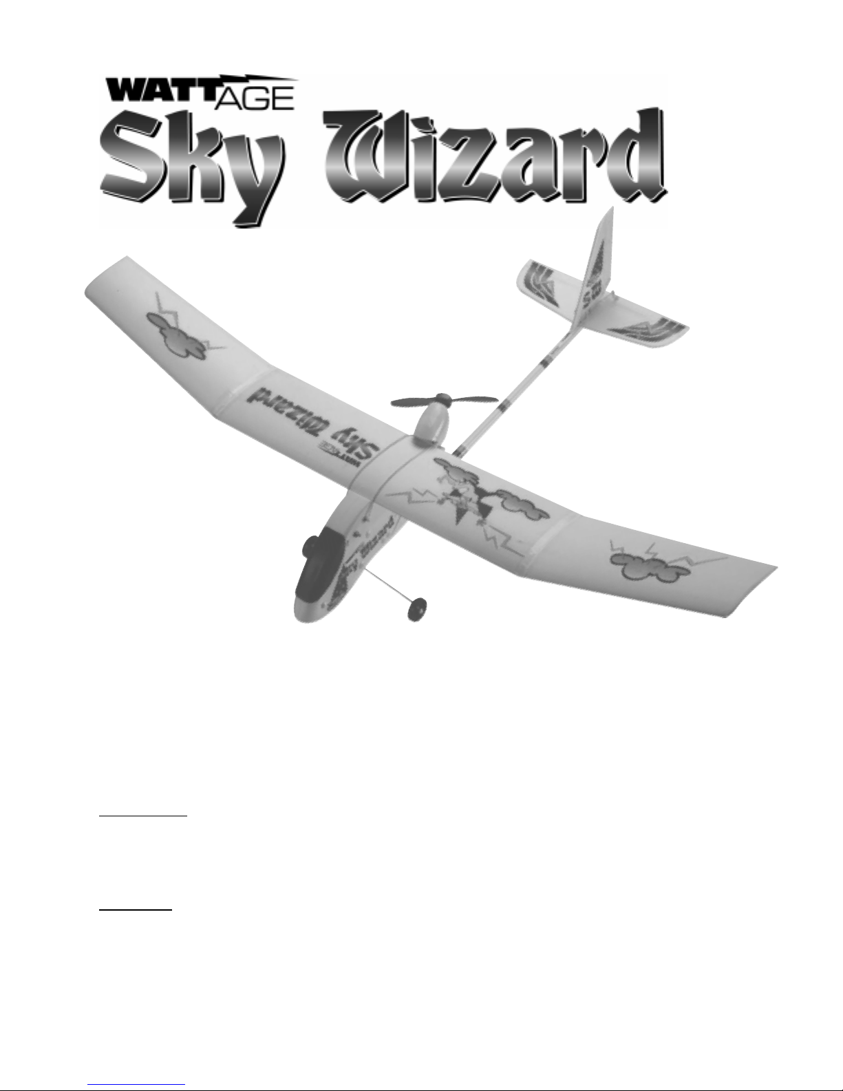
Thank you for purchasing the new Wattage Sky Wizard and welcome to the sport of radio control flying. Before
completing the final assembly of your new Sky Wizard, please carefully read through this instruction manual in its
entirety. Doing so will ensure success the first time around!
IMPORTANT
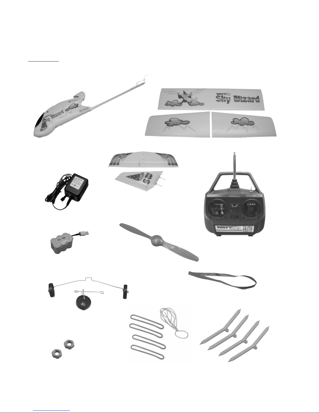
Before beginning assembly make sure you have all of the parts shown below:
Fuselage Assembly
Wing Set
Battery Charger
Flight Battery
Landing Gear Assemblies
Tail Set
3ch. Transmitter
Propeller
Transmitter Flag
2 Spare Hex
Nuts
Rubber Bands (Spares Included)
2
4 Wing Braces
and Length of String
Page 3

Here's what you'll need to get your Sky Wizard flying:
Adjustable Wrench
3/4" Wide Scotch® Tape
Eight AA Alkaline Batteries
If any of the parts listed on page # 2 are missing, or if you have any questions during assembly, please contact us. We're
here to help you. You can reach us at the following address:
Wattage Customer Care
18480 Bandilier Circle
Fountain Valley, CA 92728
Phone (714) 963-0329
Fax (714) 964-6236
E-mail: service@globalhobby.net
For Your Convenience:
W e have included a glossary of terms on page # 22. Check it out if you come across any terms that are unfamiliar to you.
We know you're excited to get your new Sky Wizard flying, but take your time. Taking your time will ensure the best
possible success and fun with the Sky Wizard.
If you encounter any problems with your Sky Wizard check the troubleshooting guide on page # 23.
OUR GUARANTEE
Wattage guarantees this kit to be free from defects in both material and workmanship, at the date of purchase. This does
not cover any component parts damaged by use, misuse or modification. In no case shall Wattage's liability exceed the
original cost of the purchased kit.
In that W attage has no control over the final assembly or material used for final assembly , no liability shall be assumed for
any damage resulting from the use by the user of the final user-assembled product. By the act of using the final userassembled product, the user accepts all resulting liability.
3
Page 4
You're ready to start, aren't you? Lets go!
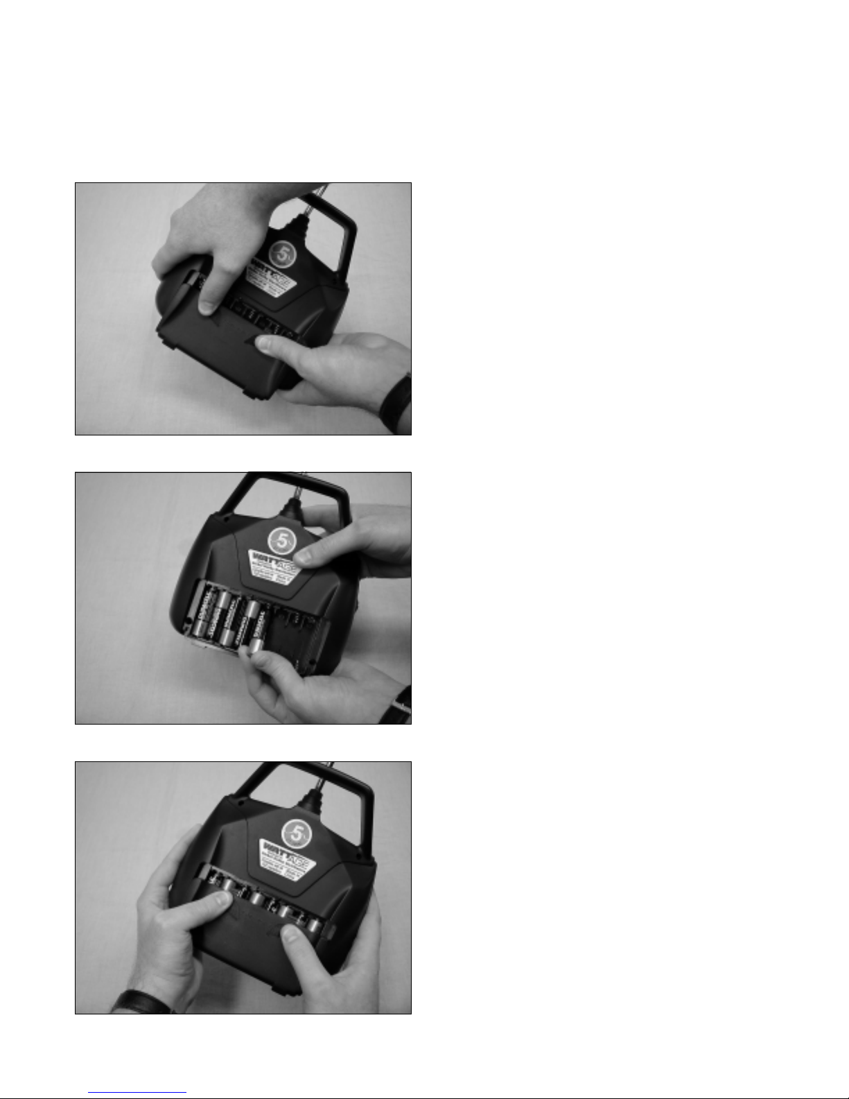
Step 1: Installing the Transmitter Batteries
❑ Remove the battery cover by pushing down with your
thumbs at the two marks shown.
❑ Install 8 fresh AA Alkaline batteries, being careful to
watch that the polarity is correct for each battery.
❑ Push the battery cover back into place until you hear
it "click" into position.
4
Page 5
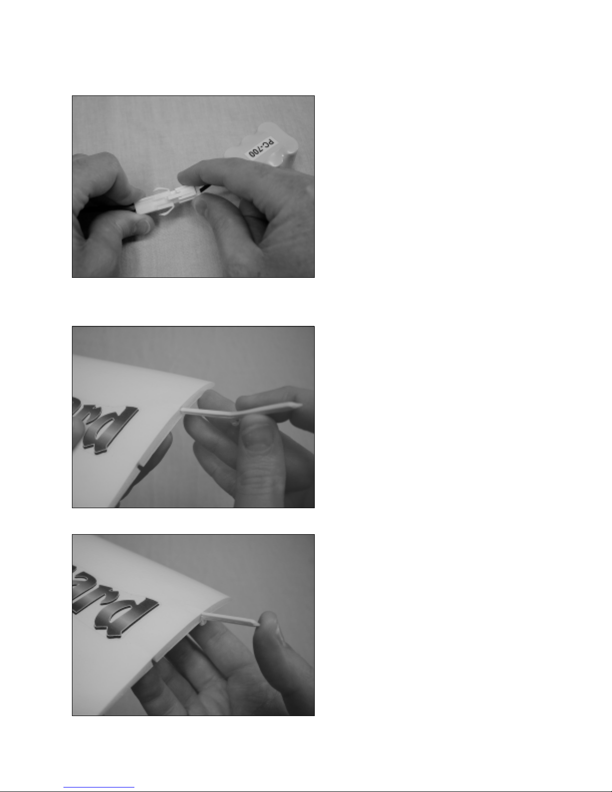
Step 2: Charging the Flight Battery
Step 3: Installing the Wing Panels
❑ Plug the flight battery connector into the battery
charger connector. When plugged in properly you should
hear the connectors "click" together.
Note that the plugs can be plugged in only one way.
☛
❑ Plug the charger into a 110V AC wall outlet.
❑ Charge the flight battery for 2 to 2-1/2 hours. Be
careful not to overcharge the battery.
❑ To unplug the connectors, squeeze the tab on the
battery connector and pull the two connectors apart.
❑ Carefully line up one plastic wing brace with the
forward hole in one end of the center wing panel.
Make sure the eyelet in the brace is pointing toward
☛
the bottom of the wing.
❑ Carefully push the wing brace firmly into the wing,
making sure to push the brace in straight so it doesn't push
out through the top or bottom of the wing skin.
Continued on Next Page
5
Page 6
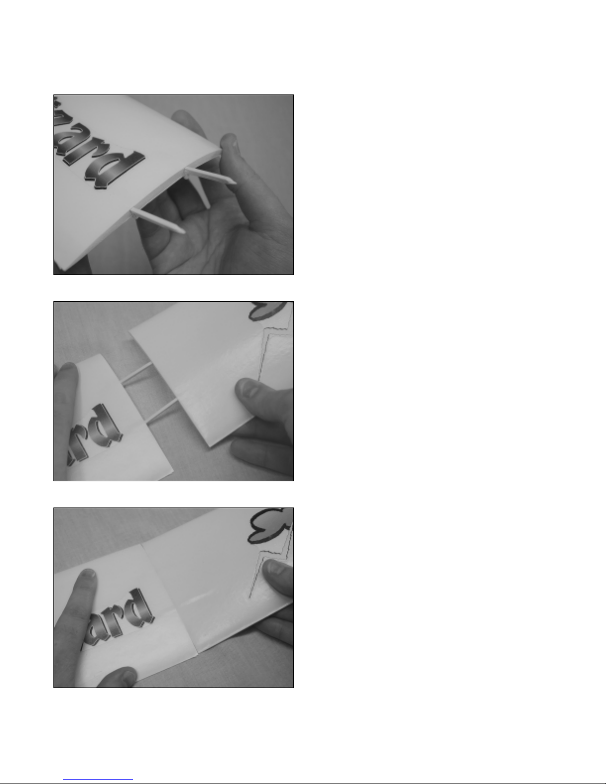
❑ Carefully push one plastic wing brace into the rear
hole using the same technique.
Push the brace in straight so it doesn't push out through
☛
the top or bottom of the wing skin.
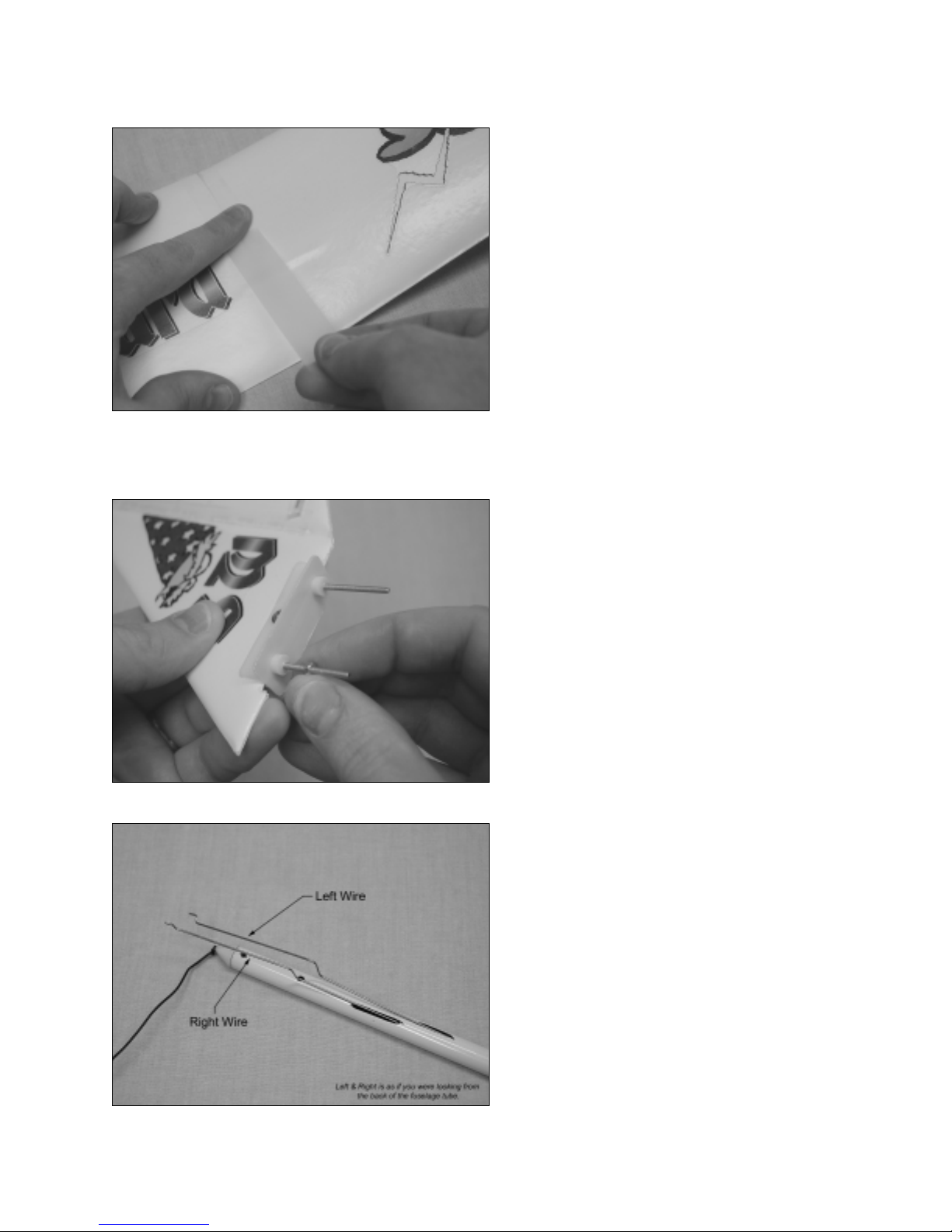
❑ Carefully line up the two holes in one outer wing panel
with the exposed ends of the plastic wing braces.
6
❑ Carefully push the outer wing panel onto the wing
braces and up against the center wing panel. Make sure
to push the wing panel on straight so the wing braces don't
push out through the top or bottom of the wing skin.
Both wing panels should be pushed firmly together
☛
as shown.
Continued on Next Page
Page 7
Step 4: Installing the Tail Assembly
❑ Apply a strip of 3/4" wide Scotch® tape to the top and
bottom of the wing joint.
The tape will keep the wing panels from pulling apart
☛
during flight.
❑ Repeat the previous steps to install the remaining outer
wing panel onto the other end of the center wing panel.
❑ Remove the two hex nuts that are preinstalled on the
tail mounting screws.
If the screws are too tight, loosen them with an
☛
adjustable wrench first.
❑ Look at the back of the fuselage tube. You will
notice one left wire and one right wire. Each wire has a
Z-shaped bend (Z-bend) at the end of it.
When you install the tail assembly in the next few
☛
steps, the left wire goes to the horizontal tail and the right
wire goes to the vertical tail.
Continued on Next Page
7
Page 8
❑ Insert the Z-bend in the left wire into the middle hole
in the plastic control horn on the top of the horizontal tail.
You will have to slightly twist the tail and the wire to
☛
easily install the Z-bend.
The plastic control horn should face up toward you.
☛
❑ When installing the Z-bend, make sure the longer
portion of the wire is facing toward the outside edge of
the plastic control horn.
8
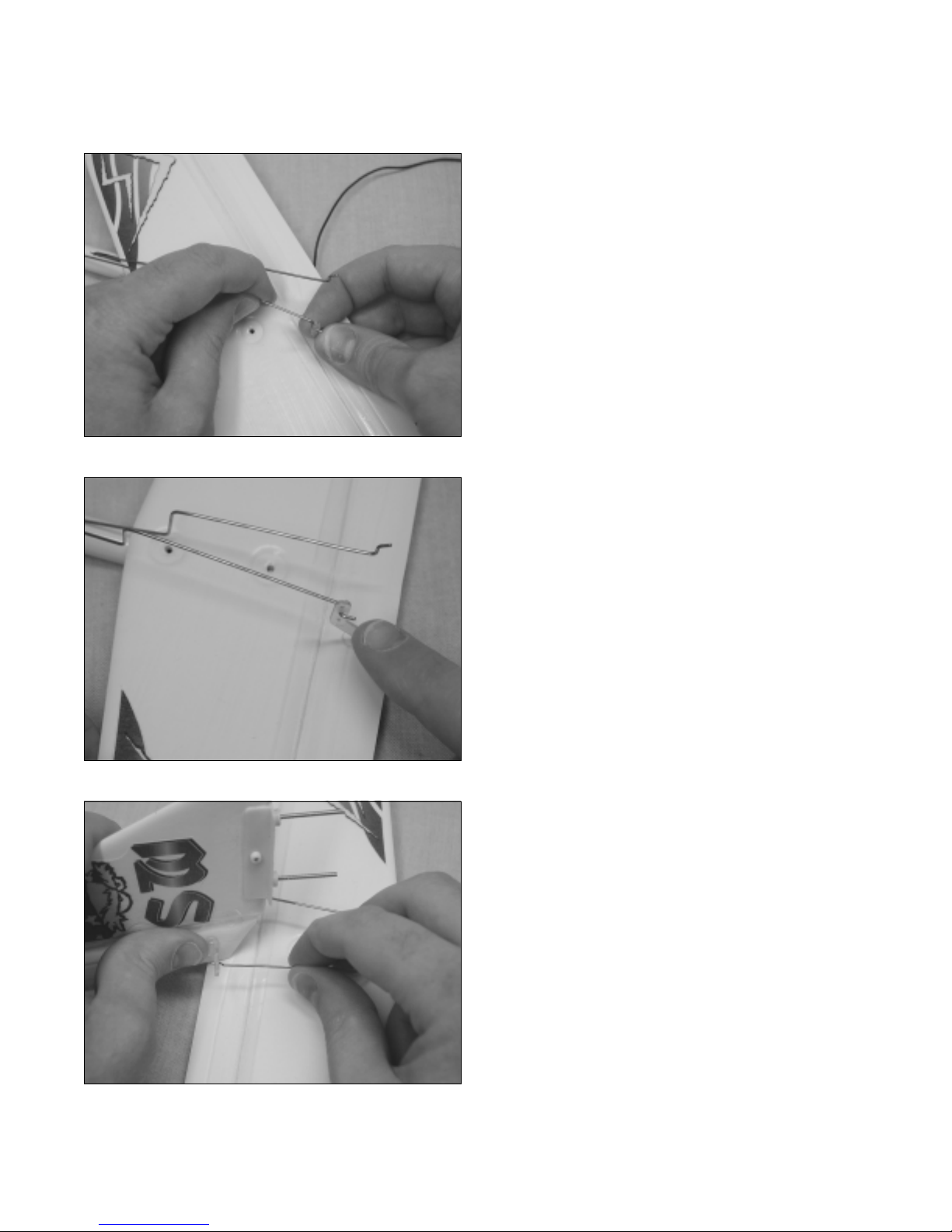
❑ Now insert the Z-bend in the right wire into the middle
hole in the plastic control horn on the right side of the
vertical tail.
You will have to slightly twist the tail and the wire to
☛
easily install the Z-bend.
Note that the longer portion of the Z-bend is toward
☛
the top of the plastic control horn.
Continued on Next Page
Page 9

❑ Line up the two tail mounting screws with the two
holes in the horizontal tail.
❑ Push the vertical tail down onto the horizontal tail.
❑ Line up the tail mounting screws with the two holes
in the fuselage tube.
❑ Push the tail assembly firmly down into place.
❑ Turn the fuselage over and slide the tail wheel over
the two tail mounting screws.
The tail wheel should point toward the back of the
☛
fuselage tube as shown.
❑ Thread one hex nut onto each mounting screw.
❑ Tighten each hex nut finger-tight.
Use an adjustable wrench to tighten the hex nuts
❑
firmly to draw the tail assembly down into place.
The tail assembly should be firmly tightened down
☛
against the fuselage tube.
9
Page 10

Step 5: Installing the Landing Gear
❑ Line up the bend in the landing gear wire with the
slot in the bottom of the fuselage.
Step 6: Installing the Propeller
❑ Push the landing gear wire firmly down into the slot.
❑ Align the propeller with the motor shaft.
10
Continued on Next Page
Page 11

Step 7: Installing the Wing
❑ Push the propeller firmly onto the motor shaft.
When pushing the propeller into place, support the
☛
back of the motor with your fingers.
❑ Set the wing onto the fuselage.
❑ Line up the two molded dots in the middle of the wing
with the molded centerline in the fuselage.
❑ Install the rubber bands to hold the wing firmly in
place.
❑ Use two rubber bands per side (four total) to hold the
wing in place.
It is not necessary to use more than four rubber
☛
bands, but if you use less, the wing may move during
flight, resulting in poor flight performance.
Continued on Next Page
11
Page 12

❑ Tie one end of the length of string to the eyelet in one
of the forward plastic wing braces.
The eyelet is on the bottom of the wing.
☛
❑ Pull the free end of the string over the bottom of
the fuselage and tie it tight to the eyelet in the opposite
forward plastic wing brace.
The string should be tight, but not so tight that it pulls
☛
the wing down and distorts its shape.
❑ If you ever need to remove the wing, remove the four
rubber bands and slide the wing (with the string still in
place) over the front of the fuselage.
Step 8: Installing the Flight Battery
12
❑ Turn on the transmitter. Both the green and the red
LED's should light up.
IMPORTANT
Always make sure you turn on the transmitter first,
before installing the flight battery. After you're done
flying, remove the flight battery first, then turn off the
transmitter .
This will prevent unexpected radio signals from in-
☛
terfering with your radio system.
Continued on Next Page
Page 13

❑ Pull the motor on/off switch back toward you to make
sure the motor is in the off position.
❑ Carefully squeeze the upper sides of the plastic
battery cover/canopy to release the latches from the
fuselage.
❑ Pull open the plastic battery cover/canopy.
❑ Plug the connector on the flight battery into the
connector that is inside the fuselage. When plugged in
properly you should hear the connectors "click".
Note that the plugs can be plugged in only one way.
☛
Continued on Next Page
13
Page 14

❑ Slide the flight battery into the styrofoam pocket in
the front of the fuselage.
The battery wires should be facing the top of the
☛
battery as shown.
❑ Push the flight battery down so it is resting on the
bottom of the fuselage.
❑ Close the battery cover/canopy, making sure the
plastic latches snap into the slots in the fuselage.
The Sky Wizard does not have an on/off switch.
☛
When you plug in the flight battery, the receiver and
servos are powered up.
Caution!
Do not press the red motor arming switch at this time.
Now that you have completed the assembly of your
Sky Wizard, turn to page # 15 to begin testing your
Sky Wizard and getting it ready to fly!
14
Page 15

Testing the Sky Wizard
Step 1: Adjusting the Control Surfaces
❑ Turn on the transmitter.
❑ Plug in and install the flight battery. Do not press the safety arming switch yet.
❑ Carefully adjust the left and right control trim lever
until it is centered with the marks above and below it.
❑ Carefully adjust the up and down control trim lever
until it is centered with the marks to the right and left of it.
IMPORTANT
Before each flight it's important to check to make sure
that each control surface is exactly even with the tail. If
they are not, the Sky Wizard will not fly properly.
❑ If the control surfaces are not exactly even with the
tail, use your fingers to carefully bend the wire (where it
comes out of the fuselage tube) until the back edge of
each control surface is even with the tail.
Continued on Next Page
15
Page 16

❑ Looking from the back of the Sky Wizard, move
the right-hand transmitter control stick completely to
the left. The vertical control surface should move left.
❑ Looking from the back of the Sky Wizard, move the
right-hand transmitter control stick completely to the
right. The vertical control surface should move right.
16
❑ Looking from the back of the Sky Wizard, move the
left-hand transmitter control stick completely back. The
horizontal control surface should move up.
Continued on Next Page
Page 17

Step 2: Testing the Motor
❑ Looking from the back of the Sky Wizard, move the
left-hand transmitter control stick completely forward .
The horizontal control surface should move down.
❑ Turn on the transmitter and plug in and install the
flight battery.
❑ Make sure that the motor on/off switch is pulled back
toward you - see page # 13.
❑ While keeping clear of the propeller, press the red
motor safety arming switch once.
WARNING:
of the propeller, especially fingers and loose clothing.
❑ While holding the Sky Wizard upright in the air with
the propeller pointing away from you, push the motor
on/off switch forward. The propeller should spin at a high
rate of speed.
❑ When finished with the test, pull the motor on/off
switch toward you (the motor should turn off), unplug the
flight battery, then turn off the transmitter.
During the motor test keep everything clear
17
Page 18

Getting Ready to Fly
Step 1: Choosing Your Flying Field
❑ The flying field you choose should be a large, open field with grass. There should not be any vehicles, buildings,
power lines, trees, large rocks - or anything else for your Sky Wizard to crash into. Until you are very proficient with the
Sky Wizard, we don't recommend taking off or landing from hard surfaces like asphalt or concrete.
Step 2: Choosing a Day to Fly
❑ Until you become a proficient flyer you should always plan on flying your Sky Wizard when there's no wind. We
strongly suggest waiting for a calm day. Do not fly in more than a 5 m.p.h. wind.
❑ Tie the red flag to the end of the transmitter's antenna.
❑ Hold the transmitter up at an angle. If the flag hangs
down, go ahead and fly.
Less than a 5 m.p.h. wind.
It's okay to fly.
❑ If the flag hangs at a 45º angle or more, don't fly.
Wait for a calmer day.
More than a 5 m.p.h. wind.
Wait for a calmer day to fly.
18
Page 19

Step 3: Range Testing the Radio System
❑ Turn on the transmitter.
❑ Plug in and install the flight battery. Do not press the motor safety arming switch yet.
❑ Set the Sky Wizard on the ground.
❑ Extend the transmitter's antenna completely. Move the two control sticks back and forth to check the controls.
❑ W alk approximately 150ft. from the Sky Wizard and move the control sticks back and forth. Check to make sure that
the Sky Wizard's controls are moving smoothly at this distance. You may need a friend to help you with this step.
If the Sky Wizard does not range check, don't fly! Please refer to the troubleshooting guide on page # 23.
☛
Flying the Sky Wizard
Step 1: Hand Launching and Setting the Trim
❑ You should always launch the Sky Wizard into the wind. Determine wind direction by tossing some blades of grass
into the air and watching which direction they fall.
❑ Turn on the transmitter and plug in and install the flight battery. Do not press the motor safety arming switch yet.
❑ In your throwing hand hold the Sky Wizard from the
base (just behind the string), up above shoulder level.
❑ While holding the transmitter in your other hand,
firmly toss the Sky Wizard straight ahead and level
(without power). Do not throw it hard or up or down.
IMPORTANT
When trimmed properly, the Sky Wizard should glide
level for a short distance then go into a shallow nose
down attitude for about 20 - 30 feet. Adjust the trim of
the horizontal control surface using the up/down trim
lever on the transmitter to achieve this - see below.
To make the Sky Wizard pitch up more, slide the up/down trim lever back just a little bit.
☛
To make the Sky Wizard pitch down more, slide the up/down trim lever forward just a little bit. In most cases,
☛
keeping the up/down trim lever centered will result in excellent power-off glide performance.
❑ When you are satisfied with the trim, press the motor arming switch once.
❑ While holding the Sky Wizard at shoulder level like before, push the motor on/off switch to turn the motor on. With
the propeller spinning at high speed, firmly toss the Sky Wizard straight ahead and level.
When trimmed properly, the Sky Wizard will gently climb on its own without being given any up/down stick input.
☛
If the Sky Wizard begins losing altitude after launching, pull back gently (only a small amount) on the up/down control
stick. This will cause the Sky Wizard to pitch up and climb.
Continued on Next Page
19
Page 20

Step 2: Flying
❑ After you've launched the Sky Wizard, keep the motor running and allow the Sky W izard to continue to climb. After
reaching about 80 - 100 feet of altitude you should start making turns to keep the Sky Wizard near you.
WARNING
Don't fly the Sky Wizard too far away or you could lose control. The range of the radio system is about 500 - 600 feet.
❑ To turn the Sky Wizard, gently move the right-hand control stick in the direction you want the Sky Wizard to go and
hold it for a second or two. After the Sky Wizard starts turning in the direction you want it to, let go of the control stick.
WARNING
The longer you hold the control stick over, the tighter radius the Sky Wizard will turn in. We recommend gentle turns
until you are proficient with the flight characteristics of the airplane.
If the Sky Wizard always turns one direction or the other, use the sliding trim lever (as described on page # 15) to
☛
make the Sky Wizard fly level.
❑ The Sky Wizard's altitude is controlled by the left-hand up/down control stick. If you want the Sky W izard to climb,
gently pull back on the control stick. If you want the Sky Wizard to descend, gently push forward on the control stick.
When going into a turn, the Sky Wizard will have a natural tendency to lose some altitude. Unless you want to
☛
descend, you should gently pull back on the control stick to keep the Sky Wizard level during the turn. The steeper the
turn the more altitude the Sky Wizard will lose.
❑ Typically, the Sky Wizard is flown with the motor on. If you want to glide around or descend, you can turn the motor
off using the motor on/off switch. When you want to climb again, push the motor on/of f switch to turn the motor back on.
When you turn the motor off for gliding, the Sky Wizard will have a natural tendency to pitch up. This is caused by
☛
the down thrust in the motor. Push forward gently on the left-hand up/down control stick to make the Sky Wizard pitch
down to level flight.
IMPORTANT
If you are flying in a light wind, the Sky Wizard will tend to climb as you turn into the wind. In this instance, you will need
to level off the Sky Wizard by pushing forward on the control stick. When you turn down-wind, the Sky W izard will have
a natural tendency to loss altitude. In this instance, you should pull back gently on the control stick.
Step 3: Landing
❑ Before attempting to land make sure that the Sky Wizard is flying straight into the wind with the wing level.
❑ Pull the motor on/off switch back toward you to turn the motor off. At this point the Sky Wizard will begin to
descend. Allow the airplane to gradually descend. If the airplane seems to be descending too fast, gently pull back on the
up/down control stick to make the Sky Wizard pitch up to level flight. This will bleed off speed and slow the decent.
Once the airplane has slowed down, release the control stick and allow the airplane to continue its decent. Once the Sky
Wizard is about 15 feet off the ground make sure the wing is level and continue a shallow descent. Just before touchdown, gently pull back on the control stick to level the airplane with the ground for landing.
20
Page 21

Flight Tips and Warnings
❑ Check before every flight to ensure that the batteries in the transmitter are working properly. When the green LED
goes out it's time to change the batteries.
❑ Before recharging the flight battery , let the motor run until the flight battery is completely drained. This will ensure
you don't overcharge the battery.
❑ Do not begin to charge the flight battery if it is hot. Wait for the battery to cool before recharging it.
❑ Never leave the flight battery plugged into the airplane unless you are flying or testing the controls.
❑ Before flying, always double check that you've extended the transmitter antenna completely.
❑ Before each flight, do a quick motor test to make sure that the motor is producing full power. If it doesn't you may
need to charge the flight battery longer . Do not charge a completely drained flight battery longer than 3 hours or damage
to the flight battery may occur.
❑ When you fly, orientate yourself so that the sun is at your back. Don't fly directly into the sun or you won't be able to
see your Sky Wizard.
❑ Separate battery packs can be purchased and charged before going to the flying field. An extra flight battery will
double your flight time. See the replacement parts list on the back page for the part number of the flight battery.
❑ Do not fly in winds over 5 miles per hour, otherwise the Sky Wizard will be very difficult to control and a crash will
likely occur.
❑ Do not fly your Sky Wizard if another airplane is on the same frequency as you. The frequency number is printed on
a sticker on the back of the transmitter and on the Sky Wizard's fuselage.
❑ Always be conscious of the spinning propeller. Be careful not to allow loose clothing to be drawn into the propeller.
❑ If you're under 12 years of age we suggest you fly while accompanied by an adult.
❑ Do not use any charger other than the charger included with the Sky Wizard to charge the flight battery.
❑ Never attempt to disassemble any of the Sky Wizard components, especially the transmitter, charger and battery.
❑ Do not allow any of the components to get wet or electrical damage may occur.
❑ The propeller is a friction fit to the motor shaft. Sometimes the propeller may be knocked loose during a crash or it
may become loose from taking it off. If this is the case, simply apply a thin layer of Elmers® White Glue to the motor
shaft before installing the propeller. This will help keep it firmly in place. Be careful not to get glue inside the motor.
21
Page 22

Glossary of Terms
This glossary is provided to help you understand terms that you may not be familiar with. It's a good idea to read through
it to learn about the different terms used throughout this assembly manual.
Battery Charger:
and charges the flight battery to full capacity.
Control Stick:
move. The one on the right moves left and right and the
one on the left moves up and down.
Control Surfaces:
that pivot to make the airplane turn right and left and pitch
up and down.
Eyelet:
cord.
A small hole used to fasten a piece of string or
Flight Battery:
the flight battery is mounted inside the airplane and powers the motor, receiver and servos.
Horizontal Tail:
the airplane that is parallel with the wing. The horizontal
tail provides stability to the airplane.
Motor Controller:
speed of the motor. The Sky Wizard's motor controller is
a simple on/off switch.
Pushrods:
servo, transferring the movement of the servo directly
to the control surfaces.
Receiver:
signals from the transmitter.
They connect the control surfaces to the
The part of the radio system that receives the
Plugs into a 110V AC wall outlet
The sticks on the transmitter that you
The surfaces on the tail assembly
Comprised of individual battery cells,
The wing-like surface on the back of
The motor controller controls the
Safety Arming Switch:
and the motor controller that prevents the motor from turning on until the switch is pressed. This prevents the motor
from inadvertently turning on.
Servo:
movement necessary to move the control surface. The
servo includes a small motor, gears and a circuit board.
Servo Horn:
the servo output shaft. The pushrod and/or servo connector are then attached to the servo horn.
Transmitter:
control. It transmits the control inputs to the receiver,
which transfers that information to the servo and motor controller.
Trim Lever:
allows you to make small adjustments to the control
surfaces from the transmitter.
Vertical Tail:
airplane that is perpendicular to the horizontal tail. The
vertical tail provides stability to the airplane.
Wing Brace:
strengthen the joint between two wing panels.
Z-Bend:
connect the pushrods to the control surfaces.
The part of the radio system that produces the
Made out of plastic or nylon, it attaches to
The part of the radio system that you
A sliding lever on the transmitter that
The wing-like surface on the back of the
Made of plastic, the wing brace is used to
A "Z Shaped" bend in pushrods that is used to
A switch between the motor
22
Page 23

Troubleshooting Guide
This troubleshooting guide has been provided to help you diagnose and solve most problems that you may encounter
with your Sky Wizard. Most problems encountered can be solved by carefully following the problem-cause-solution
sections below. If you cannot solve the problem using this troubleshooting guide, please feel free to contact us at the
address or phone number listed on page # 3.
PROBLEM CAUSE SOLUTION
1) Transmitter does not turn on A) Transmitter batteries are depleted A) Replace batteries with new ones
B) Transmitter batteries are not installed properly B) Reinstall the batteries, double checking
the polarity
2) Tail servo/servos do not work A) Flight battery is depleted A) Recharge flight battery
B) Flight battery is not plugged in or is loose B) Check that the flight battery is plugged
in firmly
C) A crash has damaged an internal component C) Return your Sky Wizard to Wattage
following the instructions on the back
cover of this manual
3) Motor does not turn on A) Flight battery is not plugged in A) Plug in flight battery
B) Flight battery is depleted B) Recharge flight battery
C) Safety arming switch not pressed C) Press safety arming switch once to
allow power to the motor
D) A crash has damaged an internal component D) Return your Sky Wizard to Wattage
following the instructions on the back
cover of this manual
4) The Sky Wizard is difficult A) You may be flying in too much wind A) Fly when it is calm outside
to control B) The control surfaces are out of trim B) Center the control surfaces by adjusting
the pushrods as described on page # 15
C) The flight battery is depleted C) Land and recharge the flight battery
D) Transmitter batteries are depleted D) Replace batteries with new ones
E) You are over-controlling the control sticks E) Be careful not to over-control. Apply
only small, gentle control inputs
5) The Sky Wizard always A) The right-hand trim lever is out of adjustment A) Adjust the trim lever on the transmitter
turns to the left or right until the Sky Wizard flies straight
without control input
6) The Sky Wizard always climbs A) The left-hand trim lever is out of adjustment A) Adjust the trim lever on the transmitter
or descends until the Sky Wizard flies level without
control input
7) Cannot trim the Sky Wizard A) Control surfaces are too far out of trim A) Readjust the pushrods as described on
using the trim levers page # 15
23
Page 24

Replacement Parts
Wattage carries a complete line of replacement parts for your Sky Wizard. Listed below are the replacement parts that
are available along with their respective part numbers for easy ordering convenience. These replacement parts can be
ordered through your local dealer or directly from Wattage by calling 1-714-963-0329.
Decal Sheet - 144140
Instruction Manual - 144141
Wing Set - 144142
Wing Joiner Hardware - 144129
Tail Assembly - 144143
Fuselage Assembly - 144144
Landing Gear Assembly - 144145
Flight Battery Charger - 144133
Flight Battery Pack - 144134
380 Electric Motor - 144135
Elite 3 Transmitter - 144147
27Mhz 3ch. Receiver - 144148
Motor Controller - 144149
Servo Unit - 144123
Pusher Propeller - 144146
Warranty Service
Before returning your Sky Wizard for warranty consideration, the status of the unit must be within the guarantee as
stated on page # 3 of this instruction manual. Do not return your Sky Wizard to the place of purchase. They are not
authorized or equipped to perform warranty work on Wattage products. When requesting warranty service, please
observe the following:
●
Crash damage will not be covered under warranty. Do not request warranty service for a crash-damaged product.
●
Always send the Sky Wizard complete with the transmitter. Please unplug and/or remove the batteries both from the
transmitter and the Sky Wizard. Please place the batteries separately in the same package.
●
Include a note detailing the problem or service you are requesting. Service cannot be provided without this
information. Include your daytime phone number, shipping address and/or email address in the event we need more
details pertaining to the service requested.
●
You may request an estimate of services at the time you return your Sky Wizard for service. An omission of this
request implies permission for Wattage to service your Sky Wizard at our discretion.
●
Include a method of payment for any service charges.
●
Send the unit to us by United Parcel Service, Federal Express or by Insured Mail. Postage is non-refundable. Send
your package to:
24
Wattage Customer Care
18480 Bandilier Circle
Fountain Valley, CA 92728
Phone (714) 963-0329
Fax (714) 964-6236
Email: service@globalhobby .net
 Loading...