

Global Hobby Sporty EP A. R. F. Instructions For Final Assembly
INSTRUCTIONS FOR FINAL ASSEMBLY
Thank you for choosing the Wattage Sporty EP as your next project. The Sporty EP is a small electric-
powered sport airplane built specifically to be flown in large parks or fields. The Sporty EP can be assembled
in three different configurations. If you want a docile Sunday-Flyer, assemble the Sporty EP as a three
channel airplane featuring elevator, rudder and throttle control. If you want your Sporty EP a little more
"snappy", assemble it with elevator, aileron and throttle control. If you want to fly your Sporty EP like a
full size aerobat, assemble it with elevator, aileron, throttle and rudder control. We even offer an
upgraded 370 size motor that will make your Sporty EP even more fun!
Features such as a molded foam fuselage, molded foam wing panels and molded foam flying surfaces
add up to make a lightweight, yet durable structure that is very easy to repair in the event of a mishap. And
because it is light weight, performance using the included 280 size motor and gear box is excellent. The
airplane is quite fast, yet is very stable throughout the entire speed range, making it a perfect choice for
both the experienced pilot and for those just graduating from their first or second airplane.
When you open the box, you will notice that you won't have much left to do or to purchase to finish your
new airplane. In addition to the usual nuts and bolts, the Sporty EP includes a 280 size motor with gear
box, a propeller, threaded wire pushrods with clevises and control horns, a prebent landing gear wire with
plastic lightweight wheels, a plastic molded cowling and a colorful decal sheet. The kit also includes the
necessary hardware to convert the Sporty EP to aileron control.
We hope you enjoy your new Wattage Sporty EP as much as we have enjoyed designing and building it
for you. If you have any questions or comments, please feel free to contact us. We have also included a
product survey in the back of this manual. After you have finished assembling the Sporty EP, please take
a moment to fill it out and send it to us. We enjoy hearing any comments or suggestions that you may have.
The Wattage Sporty EP is distributed exclusively by Global Hobby Distributors 18480 Bandilier Circle, Fountain V alley, CA 92728
All contents copyright © 2000, Global Hobby Distributors Version V1.0 11/00
1

TABLE OF CONTENTS
Safety Warning ...............................................................2
Our Recommendations...................................................3
Radio Control System..............................................3
Electronic Speed Control.........................................4
Flight Battery ...........................................................4
Battery Charger ........................................................4
Sporty EP Setup Information .........................................4
Additional Items Required .............................................5
Tools and Supplies Required ......................................... 5
Kit Contents....................................................................6
Metric Conversion Chart................................................6
Wing Assembly ..............................................................7
Joining the Wing Panels ..........................................7
Applying the Wing Reinforcement .......................... 7
Wing Mounting ..............................................................8
Joining the Fuselage Halves .......................................... 8
Installing the Wing Tubes........................................ 8
Mounting the Wing..................................................9
Tail Surfaces................................................................... 9
Aligning the Horizontal Stabilizer ..........................9
Mounting the Horizontal Stabilizer .........................9
Aligning the Vertical Stabilizer ...............................9
Mounting the Vertical Stabilizer............................10
Motor Installation.........................................................10
Installing the Gear Box Plate.................................10
Assembling the Gear Box......................................11
Installing the Gear Box Assembly.........................11
Landing Gear................................................................11
Installing the Wheels ............................................. 11
Installing the Tail Skid...........................................12
Cowling ........................................................................12
Trimming the Cowling........................................... 12
Mounting the Cowling...........................................12
Radio Installation .........................................................13
Installing the Servos .............................................. 1 3
Installing the Control Horns ..................................13
Installing the Pushrods........................................... 13
Final Assembly............................................................. 1 4
Installing the Receiver ........................................... 14
Installing the ESC .................................................. 15
Installing the Battery Tray ..................................... 15
Installing the Flight Battery ................................... 16
Applying the Decals ..............................................16
Balancing......................................................................16
Balancing the Sporty EP........................................16
Control Throws ............................................................ 16
Flying the Sporty EP .................................................... 17
Glossary of Terms ........................................................ 17
Aileron Conversion ...................................................... 18
Joining the Wing Panels ........................................ 18
Installing the Torque Rods.....................................18
Applying the Wing Reinforcement ........................ 19
Installing the Aileron Servo................................... 20
Installing the Aileron Linkage...............................20
Elevator Servo..............................................................21
Installing the Elevator Servo ................................. 21
Product Evaluation Sheet.............................................23
SAFETY WARNING
This R/C airplane is not a toy! If misused, it can cause serious bodily injury and/or damage to property. Fly only in open
areas and preferably at a dedicated R/C flying site. We suggest having a qualified instructor carefully inspect your
airplane before its first flight. Please carefully read and follow all instructions included with this airplane, your radio
control system and electronic speed control.
2

This instruction manual is designed to guide you through the entire final assembly process of your new Wattage
Sporty EP in the least amount of time possible. Along the way you'll learn how to properly assemble your new
airplane and also learn assembly tips that will help you in the future. We have listed some of our recommendations
below. Please read through them before going any further.
The Sporty EP is constructed of a combination of EEP and Closed Cell foam. It is very important
that you use no solvents, Cyanoacrylate (C/A) glue, or paint that can damage foam. If any of
these chemicals comes in contact with the foam parts, the parts will be destroyed and will not
be covered under warranty. Use only epoxy where glue is required. If you decide to paint the
Sporty EP, use a paint that will not attack foam and always test on a scrap piece first.
✔ Please read through each step before starting assembly . You should find the layout very complete and
simple. Our goal is to guide you through assembly
without any of the headaches and hassles you might
expect.
✔ There are check boxes next to each step. After you
complete a step, check off the box. This will help you
keep from losing your place.
✔ Cover your work table with brown paper or a soft
cloth, both to protect the table and to protect the individual parts.
If you should find a part missing or damaged, or have any questions about assembly, please
contact us at the address below:
Wattage Customer Care
18480 Bandilier Circle
Fountain Valley CA 92728
Phone: (714) 963-0329 Fax: (714) 964-6236 E-mail: service@globalhobby.net
OUR RECOMMENDATIONS
✔ Keep a couple of small bowls or jars handy to put
the small parts in after you open the accessory bags.
✔ We have included a glossary of terms beginning
on page # 17. Check it out if you come across a term
that is unfamiliar to you.
✔ We're all excited to get a new airplane in the air,
but take your time. This will ensure you build a straight,
strong and great flying airplane.
✔ If you come across this symbol ☛, it means that
this is an important point or an assembly hint.
The following section describes our general recommendations to help you in deciding which types of accessories to
purchase for your new Wattage Sporty EP. We have tested all of these items with the airplane and found that these
products will offer the best in performance, reliability and economy . We have also provided a more complete list on page
# 4 that shows the different ways the Sporty EP can be assembled to suit your flying style and experience.
RADIO CONTROL SYSTEM
The Sporty EP will require a minimum 3 channel radio control system with two micro servos. The radio system we
recommend using is the Hitec Focus 3 AM radio with 2 HS-81 Micro servos. This radio system includes two micro
servos, a three channel mini receiver, servo mounting hardware and a setup guide.
If you want to purchase a radio system that will be more upgradeable in the future, a four or more channel radio with
two micro servos and a mini or micro receiver will work well. If you decide to go this way, our recommendation would
be to use the Hitec Flash 4X Glider FM Computer radio with 2 HS-81 Micro servos. This is a very good radio system
that offers the capacity to grow as your experience grows.
If you already have a standard sized radio system, you will need to purchase an after-market mini or micro receiver and
two micro servos. If you need to purchase these items we recommend using the Hitec Micro 555 receiver (P/N 759118)
and two Cirrus CS-21 Micro servos.
Our Recommendations Cont.
8
3

ELECTRONIC SPEED CONTROL
To operate the motor, we suggest using a proportional electronic speed control (ESC) that features battery eliminator
circuitry (BEC) and auto-cutoff. BEC allows you to eliminate the receiver battery and uses the flight battery to control
both the motor and the radio system. Eliminating the receiver battery provides a great weight savings which effectively
increases performance. The auto-cutoff feature turns off the motor when the voltage in the battery drops too low to
operate the radio system safely. This guarantees safe operation throughout the entire flight. To obtain these features, we
suggest using the Wattage IC-5A ESC. This ESC is very small and light, which will result in an overall increase in the
performance of the airplane.
FLIGHT BATTERY
The battery you choose should be a 6 cell (7.2Volt) or 7 cell (8.4Volt) 270Mah Nickel Cadmium (NiCD) battery pack or
a 6 cell to 8 cell 650Mah Nickel Metal Hydride (NiMH) battery pack. The 7 cell and 8 cell battery packs will provide
more power, resulting in higher speed and better climb-out, but they weigh more than the 6 cell battery pack. The Nickel
Metal Hydride battery packs will give you about 25% longer run-time, but not quite as much overall power.
BATTERY CHARGER
Because the flight battery is small and it powers both the motor and the radio system, we suggest using an Automatic Delta
Peak Charger such as the Promax Activator Digital Peak Charger to charge the flight battery. It is vital to the Sporty EP's
flying performance that the battery pack be fully charged every flight, so using a peak charger is very important.
Sporty EP Setup Information
The Sporty EP can be assembled in three different configurations to suit your flying style and experience. Listed below
are the different configurations complete with our recommendations for each one. This instruction manual details the
assembly of each of these three configurations.
Configuration # 1 for Docile Sunday Flying
This configuration would be for those pilots who have just graduated from learning to fly a basic trainer, or for those
who want a very docile Sunday-Flyer. Assemble the Sporty EP using the stock motor and gear box. Use two Cirrus
CS-21 Micro servos (P/N 444227) for elevator and rudder control and assemble the wing with the stock amount of
dihedral. Use the Wattage IC-5A ESC (P/N 128482) and a 6 cell 270Mah NiCD battery pack (P/N 128516).
Configuration # 2 for More "Snappy" Flight Characteristics
This setup would be for those pilots who want a more aerobatic sport flyer. Assemble the Sporty EP using the stock
motor and gear box. Use two Cirrus CS-21 servos (P/N 444227) for elevator and aileron control and assemble the wing
with no dihedral. Use the Wattage IC-5A ESC (P/N 128482) and a 7 cell 270Mah NiCD battery pack (P/N 128517) or
an 8 cell 650Mah NiMH battery pack (P/N 128528).
Configuration # 3 for "Full-House" Aerobatics
This setup would be for those pilots who want a full-house aerobatic flyer. Assemble the Sporty EP using the
upgraded 370 size motor and gear box. Use three Cirrus CS-10 servos (P/N 444052) for elevator, rudder and aileron
control and assemble the wing with no dihedral. Use the Wattage IC-5A ESC (P/N 128482) and an 8 cell 650Mah
NiMH battery pack (P/N 128528).
Note
An after-market W attage 370 size motor (P/N 131350) is available separately . It can be purchased and installed in place
of the stock 280 size motor in any of the configurations shown above. This more powerful motor will increase the
performance of the Sporty EP and is only recommended for more experienced pilots.
4
ADDITIONAL ITEMS REQUIRED
❑ {1} Hitec Focus 3 AM Micro Radio System
❑ {1} Trinity AA Batteries - 8 Pack # 837801
❑ {1} Wattage IC-5A ESC # 128482
❑ {1} Wattage 6C 270Mah NiCD Battery # 128516
❑ {1} Promax Activator Digital Charger # 885650
❑ {1} Heavy Duty Clear Scotch® Tape # 105
❑ {1} Hitec Flash 4X FM Micro Radio System
❑ {3} Cirrus CS-10 Super Micro Servos # 444052
❑ {1} Wattage 7C 270Mah NiMH Battery # 128517
❑ {1} Wattage 8C 650Mah NiMH Battery # 128528
❑ {1} Wattage 370 Size Motor # 131350
OPTIONAL ITEMS
❑ {1} Wattage Male 2-Pin Micro Plug # 131162
The heavy duty Scotch® tape can be purchased in any drug store or supermarket. You don't have to use Scotch brand;
however, because it helps strengthen the wing, it's important that the tape have a high tensile strength. The 3M/Scotch
part number is 105.
If you decide to purchase the upgraded 370 size motor you will also need to purchase three capacitors to use as noise
suppressors. These will prevent the electric motor from causing receiver interference. Also, since the motor does not
come prewired with connectors, you will need to purchase a W attage male 2-pin micro plug as listed above. This plug
will come with sufficient wire to solder to the motor.
TOOLS AND SUPPLIES REQUIRED
❑ Kwik Bond 5 Minute Epoxy # 887560
❑ # 0 Phillips Head Screwdriver
❑ # 1 Phillips Head Screwdriver
❑ Excel Modeling Knife # 692801
❑ Adjustable Wrench
❑ Needle Nose Pliers
❑ Wire Cutters
❑ Magnum Z-Bend Pliers # 237473
❑ Electric or Hand Drill
❑ 1/16" Drill Bit
❑ 3/16" Drill Bit
❑ Straight Edge Ruler
❑ Builder's Triangle
❑ 220 Grit Sandpaper w/Sanding Block
❑ Pen or Pencil
❑ Scissors
❑ Masking Tape
❑ Rubbing Alcohol
❑ Paper Towels
❑ NHP Epoxy Mixing Sticks # 864204
❑ NHP Epoxy Mixing Cups # 864205
❑ Soldering Iron
❑ Solder
®
To make your modeling experience totally enjoyable, we recommend that you get experienced, knowledgeable help
with assembly and during your first flights. Your local hobby shop has information about flying clubs in your area
whose membership includes qualified instructors. W e also recommend that you contact the AMA at the address below.
They will be able to help you locate a flying field in your area also.
W attage guarantees this kit to be free from defects in both material and workmanship, at the date of purchase. This does not cover
any component parts damaged by use, misuse or modification. In no case shall Wattage's liability exceed the original cost of
the purchased kit.
In that Wattage has no control over the final assembly or material used for final assembly, no liability shall be assumed for any
damage resulting from the use by the user of the final user-assembled product. By the act of using the final user-assembled
product, the user accepts all resulting liability.
Academy of Model Aeronautics
5151 East Memorial Drive
Muncie IN 47302-9252
(800) 435-9262
www.modelaircraft.org
5

KIT CONTENTS
We have organized the parts as they come out of the box for easier identification during assembly. Before you begin
assembly, group the parts like we list them. This will ensure that you have all of the parts before you begin assembly and
it will also help you become familiar with each part.
If you find a part missing or damaged please call us at 1-714-962-0329 or send us an email at service@globalhobby.com
AIRFRAME ASSEMBLIES
❑ {1} Molded Foam Fuselage Top
❑ {1} Molded Foam Fuselage Bottom
❑ {1} Right Wing Panel
❑ {1} Left Wing Panel
❑ {1} Horizontal Stabilizer w/Elevator
❑ {1} Vertical Stabilizer w/Rudder
❑ {1} Molded Plastic Cowling
❑ {1} Molded Plastic Battery Tray
CONTROL ASSEMBLIES
❑ {2} 1.5mm x 400mm Threaded Pushrod Wires
❑ {2} Nylon Control Horns w/Backplates
❑ {2} Nylon Clevises
❑ {2} 1mm x 100mm Pushrod Wires w/Z-Bends
❑ {2} Prebent Aileron Torque Rods
❑ {1} Aileron Reinforcement Board
LANDING GEAR ASSEMBLY
❑ {1} Prebent Landing Gear Wire
❑ {2} Molded Plastic Wheels
❑ {2} Molded Plastic Wheel Retainers
❑ {1} Molded Plastic Tail Skid
MOTOR & GEAR BOX ASSEMBLY
❑ {1} 280 Size Motor w/Pinion Gear
❑ {1} Molded Gear Box Front w/Bushings
❑ {1} Molded Gear Box Back
❑ {1} Molded Gear Box Mounting Plate
❑ {1} 7.5 x 5 Nylon Propeller
❑ {1} Propeller Shaft w/Nylon Gear
❑ {2} 3mm Hex Nuts
❑ {2} 2.5mm x 9mm Wood Screws
❑ {4} 3mm x 10mm Self-Tapping Screws
❑ {1} Spinner Assembly
MISCELLANEOUS ITEMS
❑ {1} 4mm x 70mm Aluminum Tube
❑ {1} 4mm x 80mm Aluminum Tube
❑ {4} 4mm Nylon Sleeves
❑ {1} Wing Center Section Reinforcement Board
❑ {1} Wing Trailing Edge Reinforcement Board
❑ {4} Rubber Bands
❑ {1} Double Sided Tape
❑ {1} Molded Plastic Switch Plate
❑ {1} Decal Sheet
METRIC CONVERSION CHART
To convert inches into millimeters: Inches x 25.4 = mm
1/64" = .4mm
1/32" = .8mm
1/16" = 1.6mm
3/32" = 2.4mm
1/8" = 3.2mm
5/32" = 4.0mm
3/16" = 4.8mm
1/4" = 6.4mm
3/8" = 9.5mm
1/2" = 12.7mm
5/8" = 15.9mm
3/4" = 19.0mm
6
1" = 25.4mm
2" = 50.8mm
3" = 76.2mm
6" = 152.4mm
12" = 304.8mm
18" = 457.2mm
21" = 533.4mm
24" = 609.6mm
30" = 762.0mm
36" = 914.4mm
WING ASSEMBLY
APPLYING THE WING REINFORCEMENT
ITEMS REQUIRED
❑ {1} Right Wing Panel
❑ {1} Left Wing Panel
❑ {1} Wing Center Section Reinforcement Board
❑ {1} Wing Trailing Edge Reinforcement Board
TOOLS AND SUPPLIES REQUIRED
❑ Kwik Bond 5 Minute Epoxy
❑ 220 Grit Sandpaper w/Sanding Block
❑ Scissors
❑ Rubbing Alcohol
❑ Paper Towels
❑ NHP Epoxy Mixing Sticks
❑ NHP Epoxy Mixing Cups
If you are assembling the Sporty EP with ailerons, you
will also need the following items:
❑ {2} Prebent Aileron Torque Rods
❑ {1} Aileron Reinforcement Board
❑ Straight Edge Ruler
❑ Pen or Pencil
JOINING THE WING PANELS
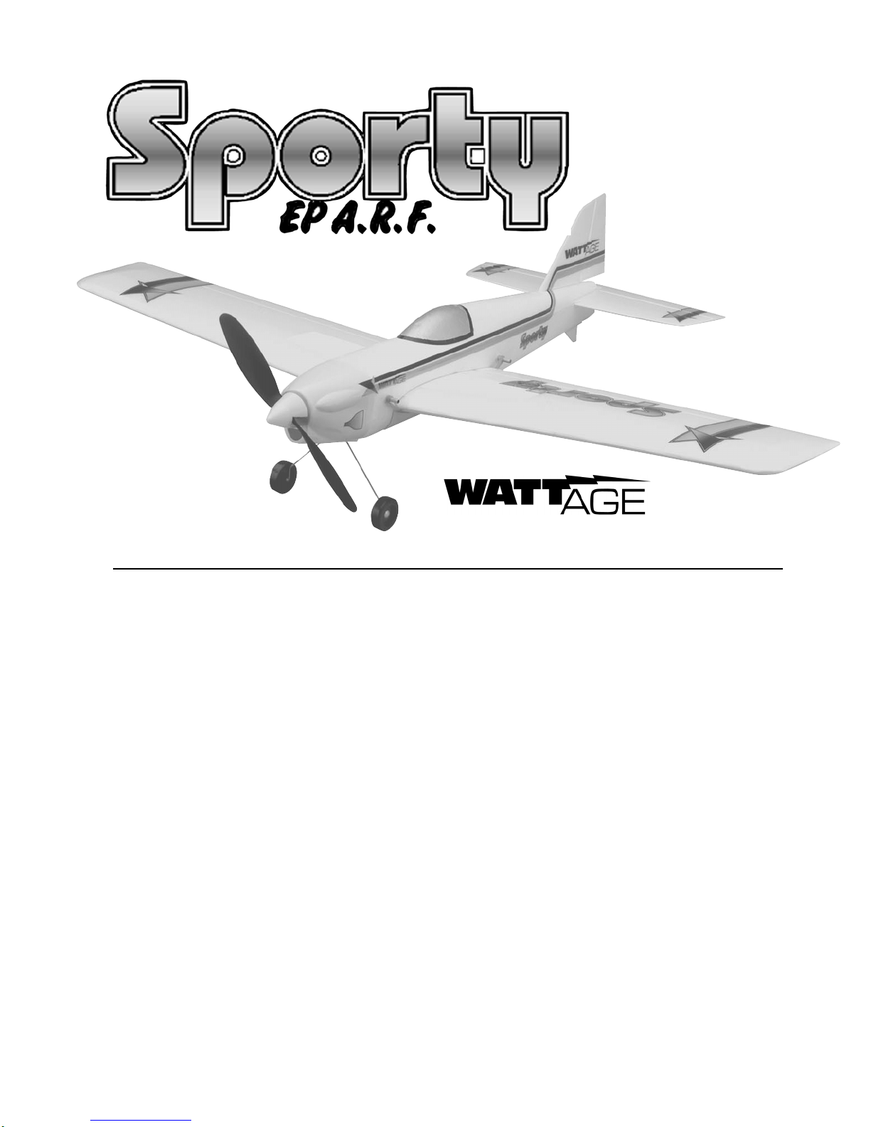
❑ 4) After the epoxy has fully cured, apply a strip of
Scotch® tape to the bottom of the wing, over the center
section joint, from the leading edge to the trailing edge.
See photo # 1 below.
Photo # 1
❑ 5) Using the same technique, apply one strip of
Scotch® tape over the center section joint on top of the wing.
❑ 6) Apply one long strip of Scotch® tape to the bot-
tom of the wing. Apply the tape down the middle of the
wing, perpendicular to the centerline joint, from wing tip
to wing tip.
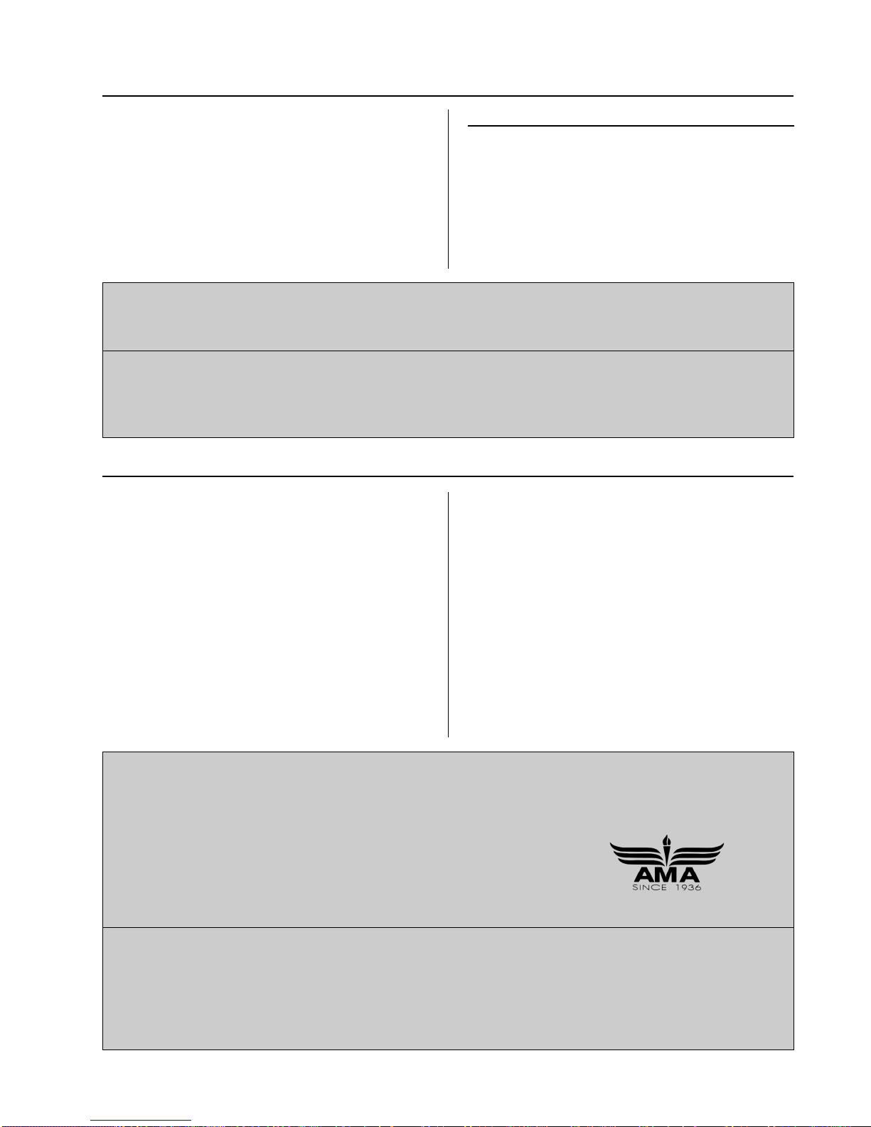
❑ 7) Carefully fold the wing trailing edge reinforcement board in half lengthwise. Remove it from its
protective backing and carefully adhere the reinforcement
board over the trailing edge of the wing at the center section. See photo # 2 below.
If you are assembling the wing with ailerons please
☛
turn to page # 18 and follow steps # 1 - # 19 under the
section "Aileron Conversion". If you are assembling
the wing without ailerons please follow the steps below.
❑ 1) Test fit the two wing panels together. They
should fit together with few or no gaps between the two,
and the leading edges and trailing edges should line up
evenly.
If the wing panels don't fit together properly, care-
☛
fully sand the root ends of each wing panel straight using
220 grit sandpaper with a sanding block. Be careful not
to change the dihedral angle.
❑ 2) Mix a generous amount of Kwik Bond 5 Minute
Epoxy. Apply a thin layer to the ends of both wing panels, making sure that you cover all of the gluing surfaces.
❑ 3) Fit the wing panels back together and realign
them. Remove any excess epoxy using a paper towel and
rubbing alcohol. Hold the wing panels together firmly
until the epoxy sets up - about 10 minutes.
Photo # 2
❑ 8) Remove the wing center section reinforcement
board from its protective backing. Carefully adhere the
reinforcement board to the top of the wing, making sure
that it's centered over the wing's center section. See
photo # 3 below.
Photo # 3
7
Because the tape and the reinforcement board add a
☛
lot of strength to the wing, it is important that they all be
pressed firmly in place.
❑ 9) Using a pair of scissors, carefully trim the back
edge of the trailing edge reinforcement board flush with
the trailing edge of the wing.
WING MOUNTING
ITEMS REQUIRED
❑ {1} Molded Foam Fuselage Top
❑ {1} Molded Foam Fuselage Bottom
❑ {1} 4mm x 70mm Aluminum Tube
❑ {1} 4mm x 80mm Aluminum Tube
❑ {4} Nylon Sleeves
❑ {4} Rubber Bands
TOOLS AND SUPPLIES REQUIRED
❑ Kwik Bond 5 Minute Epoxy
❑ Excel Modeling Knife
❑ 3/16" Drill Bit
❑ Straight Edge Ruler
❑ 220 Grit Sandpaper w/Sanding Block
❑ Pen or Pencil
❑ Masking Tape
❑ Rubbing Alcohol
❑ Paper Towels
❑ NHP Epoxy Mixing Sticks
❑ NHP Epoxy Mixing Cups
❑ 3) Fit the fuselage halves back together and realign
them. Remove any excess epoxy using a paper towel and
rubbing alcohol and use several small pieces of masking
tape to hold the fuselage halves firmly together until the
epoxy fully cures.
❑ 4) After the epoxy has cured, remove the masking
tape and carefully sand the seam between the two fuselage halves smooth using 220 grit sandpaper with a
sanding block.
INSTALLING THE WING TUBES
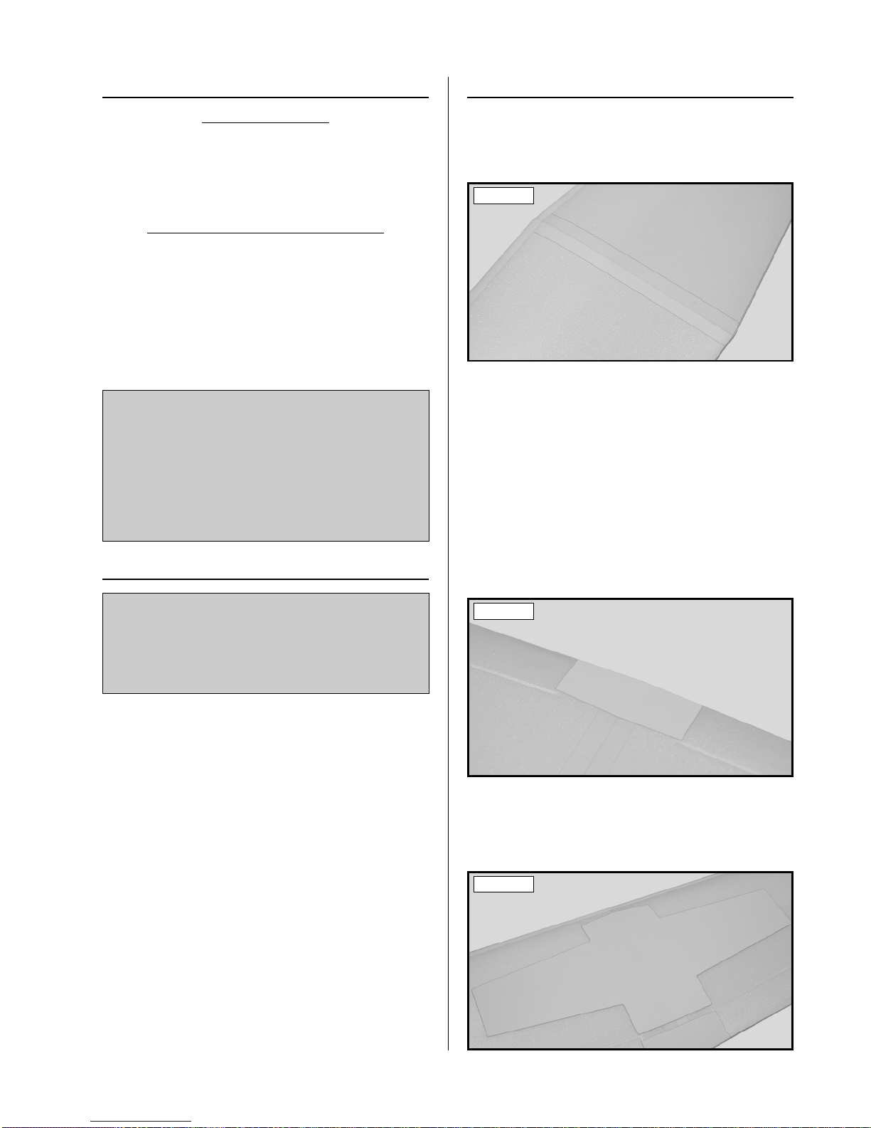
❑ 5) Using a ruler and a pencil, measure and mark the
locations of the four wing tube mounting holes. T wo holes
(one on each side) are located 1/4" in front of the wing
saddle and 1/4" above it. Two holes (one on each side)
are located 1/4" in back of the wing saddle and 1/4" above
it. See photo # 5 below.
Photo # 5
❑ 6) Using a 3/16" drill bit, carefully drill one hole
through the fuselage sides at each of the marks you drew .
JOINING THE FUSELAGE HALVES
❑ 1) Test fit the top and bottom fuselage halves together. They should fit together with few or no gaps
between the two, and the outside edges of each half should
line up evenly. See photo # 4 below.
Photo # 4
If the fuselage halves don't fit together properly, care-
☛
fully remove any irregularities using 220 grit sandpaper
with a sanding block.
❑ 2) Mix a generous amount of Kwik Bond 5 Minute
Epoxy. Apply a thin layer to the gluing surfaces of both
fuselage halves.
To prevent tearing up the foam, don't drill the holes
☛
using an electric drill. It is better to use your hand to
slowly twist the drill bit.
❑ 7) Using 220 grit sandpaper, carefully roughen the
surface of both aluminum tubes and the outer surface of
all four nylon sleeves. This will help the epoxy adhere
better to the parts when you glue them into place.
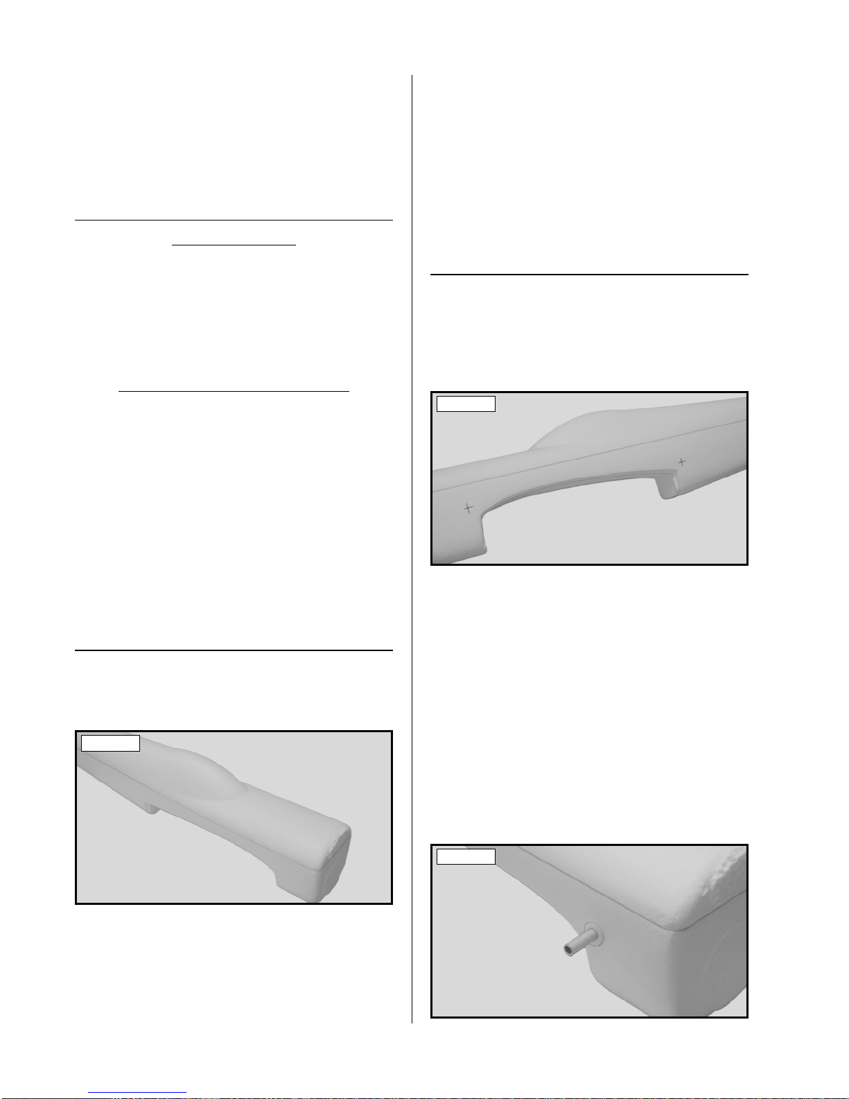
❑ 8) Push one nylon sleeve into each of the four holes.
Slide the 4mm x 80mm aluminum tube through the two
front holes and slide the 4mm x 70mm aluminum tube
through the two rear holes. See photo # 6 below.
Photo # 6
8
 Loading...