

Page 1
INSTRUCTIONS FOR FINAL ASSEMBLY
T o make your modeling experience totally enjoyable, we recommend that you get experienced, knowledgable
help with assembly and during your first flights. Your local hobby shop has information about flying clubs in
your area whose membership includes qualified instructors. W e also recommend that you contact the AMA at
the address below. They will be able to help you locate a flying field in your area also.
Academy of Model Aeronautics
5151 East Memorial Drive
Muncie, IN. 47302-9252
(800) 435-9262
www.modelaircraft.org
Global guarantees this kit to be free from defects in both material and workmanship, at the date of purchase. This does
not cover any component parts damaged by use, misuse or modification. In no case shall Global's liability exceed
the original cost of the purchased kit.
In that Global has no control over the final assembly or material used for final assembly, no liability shall be assumed
for any damage resulting from the use by the user of the final user-assembled product. By the act of using the final
user-assembled product, the user accepts all resulting liability.
The Right Flyer 60H ARF is distributed exclusively by Global Hobby Distributors
18480 Bandilier Circle Fountain Valley, CA 92728
All contents copyright © 2000, Global Hobby Distributors Version V1.0 7/00
1
Page 2

TABLE OF CONTENTS
Introduction ............................................................3
Our recommendations ............................................4
Kit Contents............................................................7
Metric Conversion Chart ........................................8
Full Size Hardware Diagrams ................................9
Additional Items Required ................................. 10
T ools and Supplies Needed ..................................10
A Note About Covering ....................................... 1 1
Wing Assembly .................................................... 1 1
Installing the Dihedral Brace .........................11
Joining the Wing Halves................................12
Wing Installation ..................................................12
Installing the Wing Dowels ...........................12
Aligning the Wing..........................................13
Mounting the Wing ........................................13
Horizontal Stabilizer.............................................13
Mounting the Horizontal Stabilizer ...............13
Vertical Stabilizer .................................................14
Aligning the Vertical Stabilizer .....................14
Mounting the Vertical Stabilizer ....................15
Control Surface Hinging ......................................15
Hinging the Ailerons......................................15
Hinging the Elevator ......................................16
Hinging the Rudder........................................16
Main Landing Gear ..............................................17
Installing the Main Gear Wires......................17
Installing the Main Gear Wheels ...................18
Nose Gear .............................................................18
Installing the Nose Gear Strut........................18
Installing the Nose Gear Wheel .....................19
Fuel T ank..............................................................19
Stopper Assembly ..........................................19
Installing the Stopper .....................................20
Installing the Fuel Tank .................................20
Engine Installation................................................21
Aligning the Engine .......................................21
Mounting the Engine .....................................21
Installing the Throttle Pushrod ......................22
Installing the Fuel Lines ................................22
Installing the Spinner .....................................22
Servo Installation..................................................23
Installing the Fuselage Servo Tray ................23
Installing the Aileron Servo Tray ..................23
Installing the Servos .............................................24
Throttle Pushrod ...................................................25
Installing the Servo Connector ......................25
Adjusting the Throttle Linkage......................26
Elevator Pushrod ..................................................26
Installing the Control Horn ............................26
Installing the Pushrod ....................................26
Adjusting the Elevator Pushrod .....................28
Rudder Pushrod ....................................................28
Installing the Control Horn ............................28
Installing the Pushrod ....................................29
Adjusting the Rudder Pushrod.......................30
Aileron Pushrods ..................................................31
Installing the Pushrods...................................31
Adjusting the Aileron Pushrods.....................32
Final Assembly.....................................................32
Installing the Switch ......................................32
Installing the Battery and Receiver................33
Applying the Decals.......................................33
Balancing ..............................................................34
Balancing the Right Flyer 60H ......................34
Control Throws.....................................................34
Preflight Check.....................................................34
Safety ....................................................................35
ABC's of Flying....................................................35
Basics of Flight.....................................................36
Glossary of T erms.................................................38
Product Evaluation Sheet .....................................43
SAFETY WARNING
This R/C airplane is not a toy! If misused, it can cause serious bodily injury and/or damage to property. Fly only
in open areas and preferably at a dedicated R/C flying site. We suggest having a qualified instructor carefully
inspect your airplane before its first flight. Please carefully read and follow all instructions included with this
airplane, your radio control system and your engine.
2
Page 3

INTRODUCTION
Thank you for choosing the Global Right Flyer 60H ARF and welcome to the exciting world of R/C modeling!
Whether you have built and flown other R/C airplanes in the past, or if this is your first, you will appreciate the
high quality, easy assembly and excellent flight characteristics of the Right Flyer 60H ARF.
The Right Flyer 60H was designed by expert modelers to be the very best sport trainer available today. It
features a constant cord wing that provides excellent slow-flight handling and forgiving flight characteristics.
The wing's airfoil is semi-symmetrical, so you can learn aerobatics and inverted flight also! A long tail moment
and large tail surfaces help the airplane fly very smooth and stable throughout the entire speed range, and the
rugged tricycle landing gear makes takeoffs and landings a breeze, too. We think that you will agree this
combination makes the Right Flyer 60H the best flying sport trainer at any flying field. Above all else, though,
the Right Flyer 60H is big! This makes learning to fly much easier, because you can see the airplane better and
because it is much more stable in wind than a smaller airplane.
When you open up the box, you'll notice that you won't have much left to do or to purchase to finish your
new airplane. Unlike other trainer kits, the Right Flyer 60H is a complete kit. Wheels, fuel tank, pushrods,
clevises and spinner are all included. The airframe is completely built and covered by master craftsmen, who
take their time to ensure that every part is straight and properly glued, and you'll love the fact the large horizontal
stabilizer is removable! This makes it much easier to transport.
W e hope you enjoy your new Right Flyer 60H ARF as much as we have enjoyed designing and building it
for you. If you have any questions or comments, please feel free to contact us. W e have also included a product
survey in the back of this manual. Please take the time to fill it out and send it to us. We would enjoy hearing
any comments or suggestions you may have.
This instruction manual is designed to guide you through the entire final assembly process of your new
Right Flyer 60H ARF in the least amount of time possible. Along the way you'll learn how to properly
assemble your new airplane and also learn many tips that will help you in the future. We have listed some
of our recommendations below. Please read through them before going any further.
ü Please read through each step before starting
assembly. You should find the layout very complete and simple. Our goal is to guide you through
assembly without any of the headaches and hassles
you might expect.
ü There are check boxes next to each step. After
you complete a step, check off the box. This will
help you keep from losing your place.
ü Cover your work table with brown paper or a
soft cloth, both to protect the table and to protect
the individual parts.
If you should find a part missing or damaged, or have any questions about assembly , please contact us at the
address below:
ü Keep a couple of small bowls or jars handy to
put the small parts in after you open the accessory
bags.
ü We have included a glossary of terms beginning on page # 38. Check it out if you come across
a term that is unfamiliar to you.
ü We're all excited to get a new airplane in the
air, but take your time. This will ensure you build
a straight, strong and great flying airplane.
ü If you come across this symbol , it means
that this is an important point or an assembly hint.
?
Global Hobby Distributors Customer Care
18480 Bandilier Circle
Fountain Valley, CA 92728
Phone: (714) 963-0329
Fax: (714) 964-6236
E-mail: service@globalhobby.net
3
Page 4
OUR RECOMMENDATIONS
The following section describes our recommendations to help you in deciding which types of accessories to
purchase for your new Right Flyer 60H ARF . We have tested all of these items with the airplane and found that
these products will offer the best in performance, reliability and economy.
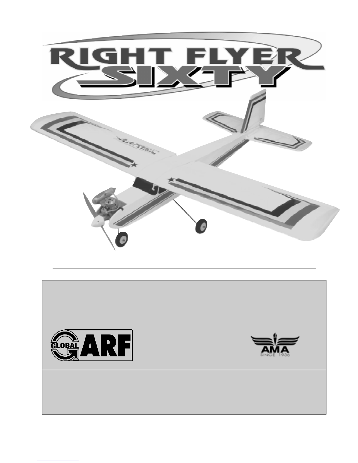
RADIO SYSTEM
The Right Flyer 60H ARF requires a minimum 4 channel radio control system that includes four standard size
servos. The radio system we recommend using is the
Hitec Focus 4 FM radio from Hitec. This particular radio system includes the transmitter, receiver, four
standard servos, rechargeable transmitter and receiver
battery packs, a standard wall charger, switch, servo
mounting hardware and a setup guide. It is priced right
and can be used in other airplanes as you advance.
Focus 4 FM
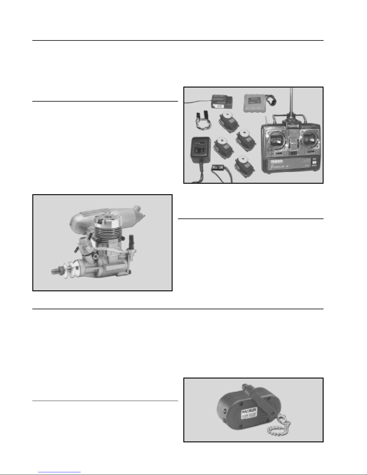
ENGINE
The Right Flyer 60H ARF requires a .61 - .75 size two
stroke engine. The engine that we recommend is the
Magnum XL .61ARNV with remote needle valve. This
engine is a perfect match to the Right Flyer 60H, both in
power and in ease of installation. The rear-mounted
needle valve assembly makes tuning the engine easy and
safe.
P/N 210803
FIELD SUPPORT EQUIPMENT
Most people getting into R/C worry most about getting the correct accessories for their airplane (radio, engine,
etc.), and that is important. But a lot of people don't put as much effort into the field support equipment they
choose. Field support equipment is a necessary and important part of flying R/C airplanes. Without it, how do
you fuel your airplane, start the engine and do maintenance? Having the proper field support equipment is just
as important as having the correct engine and radio system. Below we detail two types of field support setups.
One is the bare minimum that will be required. The second setup will cost a little bit more, but if you're planning
on staying in the hobby, it's the best way to go in the long run.
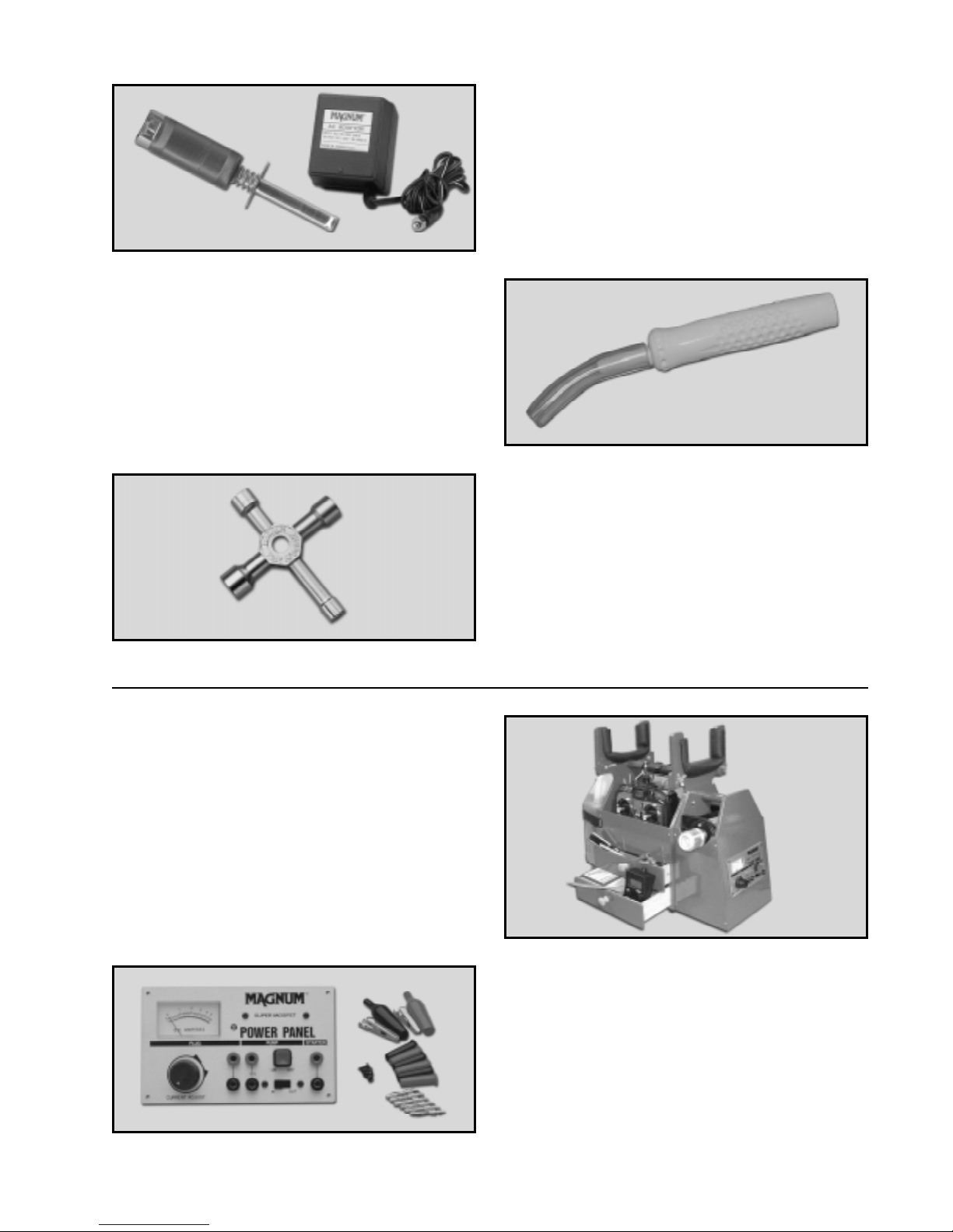
MINIMUM SETUP
Magnum Hand Crank Fuel Pump - This is a handoperated fuel pump that makes filling the fuel tank easy
and hassle-free.
4
P/N 237365
Page 5
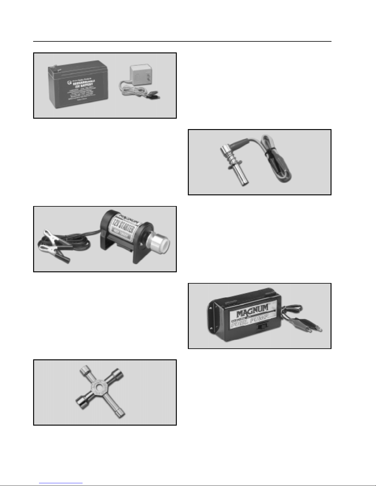
P/N 237438
Sullivan Chicken Stick - Instead of using your fingers
to flip the propeller and start your engine, you use this
rubber stick. It prevents sometimes nasty cuts and
scratches to your fingers. This is a must-have item for
hand-starting your engine.
Magnum Glow Starter - This cordless glow starter is
used to heat up the engine's glow plug for starting. It
includes a built-in meter that tells you your glow plug's
status. A battery charger is included to charge the unit
after use. You can start your airplane's engine right on
the flight line with this one if you need to.
P/N 577292
Magnum 4-Way Wrench - Use this wrench for your
engine prop nut and glow plug. It has four different
sized sockets built into one wrench, so this is the only
wrench you'll need on the flight line. It also includes
threaded inserts to hold extra glow plugs.
P/N 237420
RECOMMENDED SETUP
Global Super Box RTU Field Box - This field box is
already assembled, painted and Ready-T o-Use. It is ideal
for carrying all of your field equipment and supplies,
including a one gallon fuel bottle. It is built from plywood, so it will last for many years to come. (Note:
Accessories shown with field box not included.)
P/N 122500
Magnum Power Panel - This panel mounts directly to
your flight box. It features a 12V starter outlet, 12V
fuel pump outlet and a one-touch glow ignitor outlet
with meter.
P/N 237390
Continued on Next Page
Ü
5
Page 6
RECOMMENDED SETUP - CONTINUED
P/N 110171 & 110270
Magnum Locking Glow Connector - Used with your
power panel, the locking glow connector is used to heat
up the engine's glow plug for starting.
Global 12V Sealed Cell Battery and Charger - This
battery is a 7Amp battery that is maintenance-free. It
mounts in your flight box and provides power to your
12V accessories. The charger fully charges the battery
in about 8 hours.
P/N 237440
P/N 361006
Magnum 12V Fuel Pump - This fuel pump is used with
your power panel and mounts directly to your flight box.
It quickly fuels or drains your fuel tank with the simple
press of a button.
Magnum 12V Starter - This starter is used with your
power panel. It uses a powerful DC motor to start engines in the .10 - .61 size range. It features a rubber
starter cone insert that won't damage your airplane's
spinner assembly .
P/N 237377
Magnum 4-Way Wrench - Use this wrench for your
engine prop nut and glow plug. It has four different
sized sockets built into one wrench, so this is the only
wrench you'll need on the flight line. It also includes
threaded inserts to hold extra glow plugs.
P/N 237420
6
Page 7
KIT CONTENTS
W e have organized the parts as they come out of the box for easier identification during assembly. Each photo
below represents the parts that are required in a main section of the assembly process. Before you begin
assembly, group the parts like we show. This will ensure that you have all of the parts before you begin
assembly and it will also help you become familiar with each part. The corresponding part number is listed first,
then the quantity of that particular part, along with a short description of the part. As you proceed through
assembly, you will notice the same part number listed next to a particular part necessary for that step. If you
have any questions as to what that part might be, refer back to this section.
AIRFRAME ASSEMBLIES
1
5
3
2
1
q {1} Fuselage w/Pushrod Housings
2
q {1} Left Wing Half w/Aileron & Hinges
3
q {1} Right Wing Half w/Aileron & Hinges
4
q {1} Horizontal Stabilizer w/Elevator & Hinges
5
q {1} Vertical Stabilizer w/Rudder & Hinges
MAIN GEAR ASSEMBLY
WING ASSEMBLY
13
16
17
4
15
13
q {1} Plywood Dihedral Brace
14
q {2} Balsa Aileron Servo Tray Bocks
15
q {1} Plywood Aileron Servo Tray
16
q {1} 1/4 x 6 Hardwood Dowel
17
q {1} 1/4 x 5-1/2 Hardwood Dowel
14
FUEL TANK ASSEMBLY
7
6
10
12
11
6
q {2} Prebent Main Gear Wires
7
q {2} 75mm Diameter Wheels w/5mm Axle Hubs
8
q {2} Metal Landing Gear Straps
9
q {4} 3mm x 12mm Wood Screws
10
q {2} 5mm Nylon Spacers
11
q {2} 5mm Wheel Collars
12
q {2} 3mm x 6mm Machine Screws
18
21
8
22
9
18
q {1} 360cc Molded Fuel Tank
19
q {3} Aluminum Tubes
20
q {1} Rubber Stopper
21
q {1} 20mm Diameter Front Plate
22
q {1} 17mm Diameter Back Plate
23
q {1} Silicon Fuel Tubing
24
q {1} Weighted Fuel Pickup
25
q {1} 3mm x 19mm Machine Screw
19
Continued on Next Page
25
24
20
23
Ü
7
Page 8
NOSE GEAR ASSEMBLY PUSHROD ASSEMBLIES
27
26
39
42
41
28
29
31
26
q {1} Prebent Nose Gear Strut
27
q {1} 75mm Diameter Wheel w/4mm Axle Hub
28
q {1} Nylon Steering Arm
29
q {1} 4mm Nylon Spacer
30
q {3} 4mm Wheel Collars
31
q {4} 3mm x 6mm Machine Screws
30
PUSHROD CONNECTOR ASSEMBLIES
32
33
34
32
q {2} Nylon Control Horns
33
q {2} Nylon Backplates
34
q {4} 2mm x 20mm Machine Screws
35
q {6} Nylon Clevises
36
q {2} Nylon Snap Keepers
37
q {2} Adjustable Servo Connector Assemblies
35
37
METRIC CONVERSION CHART
40
38
38
q {2} 2mm x 120mm Threaded Wires w/L-Bends
39
q {2} 4mm x 655mm Nylon Pushrod Tubes
40
q {4} 2mm x 150mm Threaded Wires
41
q {1} 1.5mm x 460mm Plain Wire w/Z-Bend
42
q {1} 1.5mm x 500mm Plain Wire w/Z-Bend
MISCELLANEOUS PARTS
49
36
44
45
43
q {1} Plywood Fuselage Servo Tray
44
q {4} 4mm x 25mm Machine Screws
45
q {8} 4mm Flat Washers
46
q {4} 4mm Nylon Insert Nuts
47
q {4} 3mm x 16mm Machine Screws
48
q {4} 3mm Flat Washers
49
q {1} Plastic Spinner Assembly
50
q {2} 2.5mm x 12mm Wood Screws
51
q {1} Decal Set (not pictured)
43
50
47
46
48
To convert inches into millimeters: Inches x 25.4 = MM
1/64” = .4mm
1/32” = .8mm
1/16” = 1.6mm
3/32” = 2.4mm
1/8” = 3.2mm
5/32” = 4.0mm
3/16” = 4.8mm
1/4” = 6.4mm
3/8” = 9.5mm
1/2” = 12.7mm
5/8” = 15.9mm
3/4” = 19.0mm
8
1” = 25.4mm
2” = 50.8mm
3” = 76.2mm
6” = 152.4mm
12” = 304.8mm
18” = 457.2mm
21” = 533.4mm
24” = 609.6mm
30” = 762.0mm
36” = 914.4mm
Page 9

FULL SIZE HARDWARE DIAGRAMS
Shown below are full size drawings of the small hardware parts included with the Right Flyer 60H ARF. Use
these drawings to familiarize yourself with each part. Please refer back to this page to locate the proper parts
when they are needed for a particular assembly step. These drawings are especially helpful when trying to
identify the different size screws or nuts used in a particular step.
4mm x 25mm
Machine Screw
3mm x 12mm
Wood Screw
4mm Nylon
Spacer
4mm Nylon
Insert Nut
3mm x 19mm
Machine Screw
2.5mm x 12mm
Wood Screw
4mm Wheel
Collar
Nylon
Clevis
3mm x 16mm
Machine Screw
3mm x 6mm
Machine Screw
5mm Nylon
Spacer
Landing Gear
Strap
2mm x 20mm
Machine Screw
4mm Flat
W asher
5mm Wheel
Collar
3mm Flat
W asher
Adjustable Servo
Connector Assembly
Nylon Snap
Keeper
Nylon Control
Horn Backplate
Nylon Control
Horn
9
Page 10
ADDITIONAL ITEMS REQUIRED
1
2
7
1
q {1}Hitec Focus 4FM Radio w/4 Servos
2
q {1}Magnum XL .61ARNV # 210803
3
q {1}APC 12 x 6 Propeller # 608660
4
q {1}Thunderbolt Glow Plug # 115493
5
q {1}Global Silicon Fuel Tubing # 115923
6
5
q {1}Dubro 1/4” Foam Rubber # 868638
7
q {1}Beacon # 64 Rubber Bands # 925040
6
3
4
TOOLS AND SUPPLIES NEEDED
18
8
10
1
q Kwik Bond Thin C/A # 887500
2
q Kwik Bond Thick C/A # 887510
3
q Kwik Bond 30 Minute Epoxy # 887565
4
q Silicon Sealer # 335407
5
q # 1 Phillips Head Screwdriver
6
q # 2 Phillips Head Screwdriver
7
q Excel Modeling Knife # 692802
8
q Needle Nose Pliers
9
q Wire Cutters
10
q Electric or Hand Drill
11
q 1/16” Drill Bit
12
q 5/64” Drill Bit
13
q 11/64” Drill Bit
7
9
14
6
13
12
11
5
15
21
19
16
20
14
15
16
17
18
19
20
21
22
23
24
25
23
q 5/16” Drill Bit
q 12” Straight Edge Ruler
q Scissors
q Waxed Paper
(not pictured)
q Masking T ape
q 220 Grit Sandpaper w/Sanding Block
q Pen or Pencil
q Builders Triangle
q Paper Towels
(not pictured)
q Rubbing Alcohol
q NHP Epoxy Mixing Sticks # 864204
q NHP Epoxy Mixing Cups # 864205
3
24
1
2
25
4
10
Page 11
A NOTE ABOUT COVERING
The covering material used on the Right Flyer 60H
is a heat shrink polyester material. Because of this, it
is possible that with heat and humidity changes the
covering on your airplane may wrinkle or sag. This
trait is inherent in all types of heat shrink covering
material. To remove the wrinkles you will need to
purchase, or borrow from a fellow modeler, a heat iron.
If you need to purchase one, the Global Heat Sealing
Iron # 360900 is recommended.
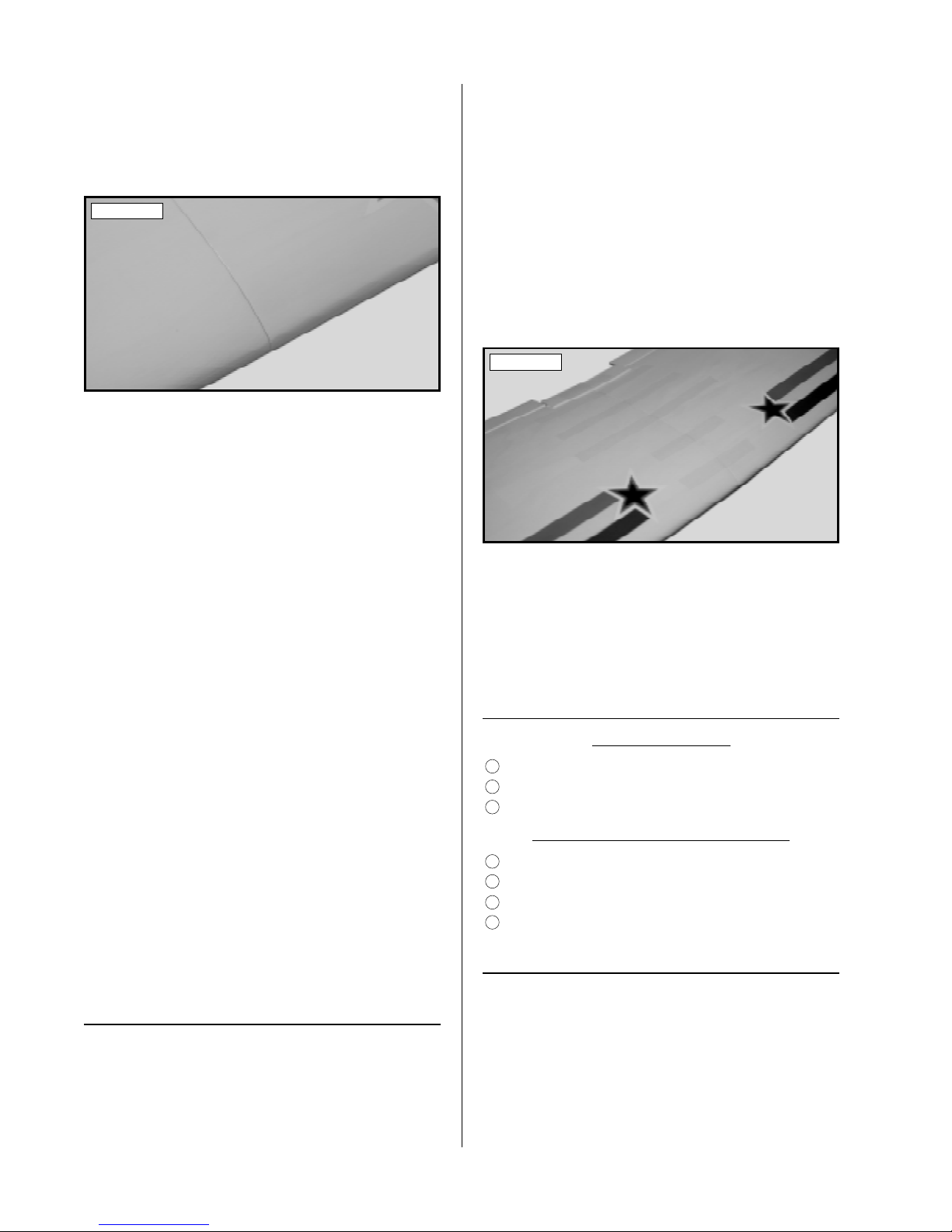
covering material overlapping so it does not pull
away later. See photo # 1 below.
Photo # 1
Follow these simple steps to remove the wrinkles:
q 1) Plug in and turn on the sealing iron to the
medium temperature setting. Allow the iron to heat
up for approximately 5 - 7 minutes.
q 2) After the iron has reached temperature,
lightly apply the iron to the wrinkled section of
the covering. Move the iron slowly over the
wrinkled section until the covering tightens and the
wrinkles disappear. You will notice that the color
of the covering will darken when it is heated. When
the covering cools back down, it will return to its
normal color.
WING ASSEMBLY
PARTS REQUIRED
2
q {1} Left Wing Half w/Aileron & Hinges
3
q {1} Right Wing Half w/Aileron & Hinges
13
q {2} Plywood Dihedral Brace
TOOLS AND SUPPLIES REQUIRED
3
q Kwik Bond 30 Minute Epoxy
7
q Excel Modeling Knife
15
q 12” Straight Edge Ruler
18
q Masking Tape
19
q 220 Grit Sandpaper w/Sanding Block
20
q Pen or Pencil
22
q Paper Towels
23
q Rubbing Alcohol
24
q NHP Epoxy Mixing Sticks
25
q NHP Epoxy Mixing Cups
Removing most of the covering from the two
?
root ribs will expose more of the wood. This will
result in a stronger joint when the wing halves are
epoxied together later.
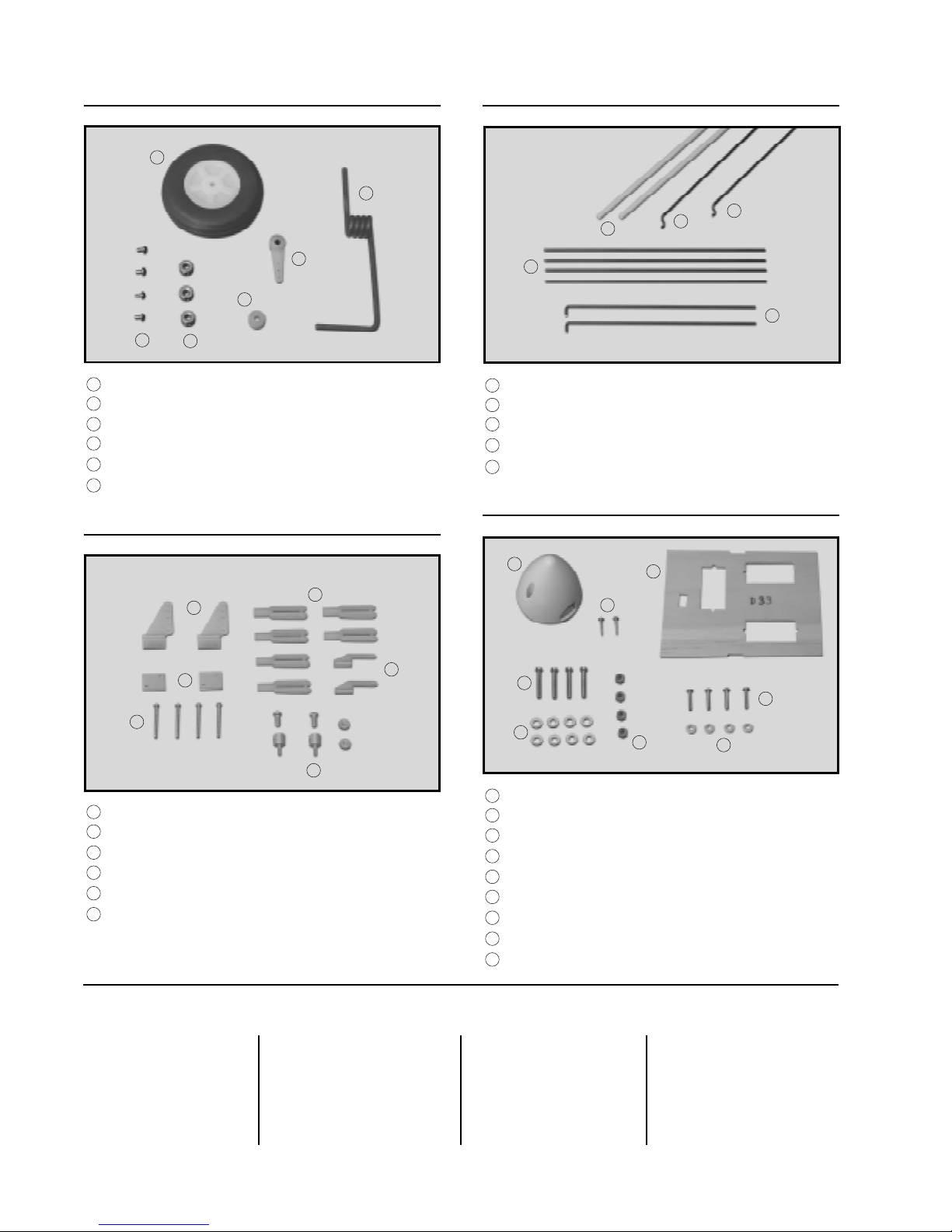
q 2) Using a straight edge ruler and a pen, locate
and mark the centerline of the plywood dihedral brace.
Draw one vertical line, on each side of the brace, at
this location. See photo # 2 below.
Photo # 2
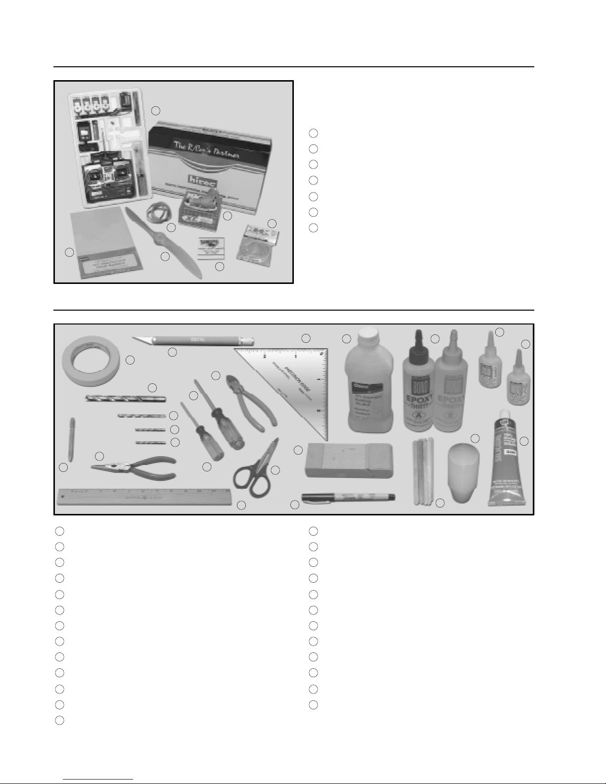
q 3) Test fit the plywood dihedral brace into the
plywood dihedral brace box in each wing half. The
brace should slide into each wing half up to its centerline. If it does not, remove the brace and lightly
sand the edges and tips until the proper fit is obtained.
See photo # 3 below.
Photo # 3
INSTALLING THE DIHEDRAL BRACE
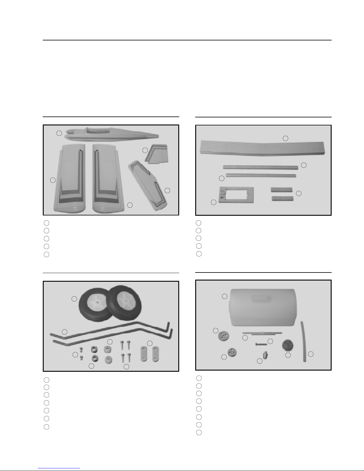
q 1) Look carefully at the surface of each root rib
on both wing halves. Notice how the excess covering material overlaps onto them. Using a modeling
knife, carefully trim and remove the excess from both
of the root ribs, leaving about 1/16” of
The dihedral brace is cut in the shape of a "V".
?
The "V" shape should face the top surface of the wing
when the brace is installed.
11
Page 12
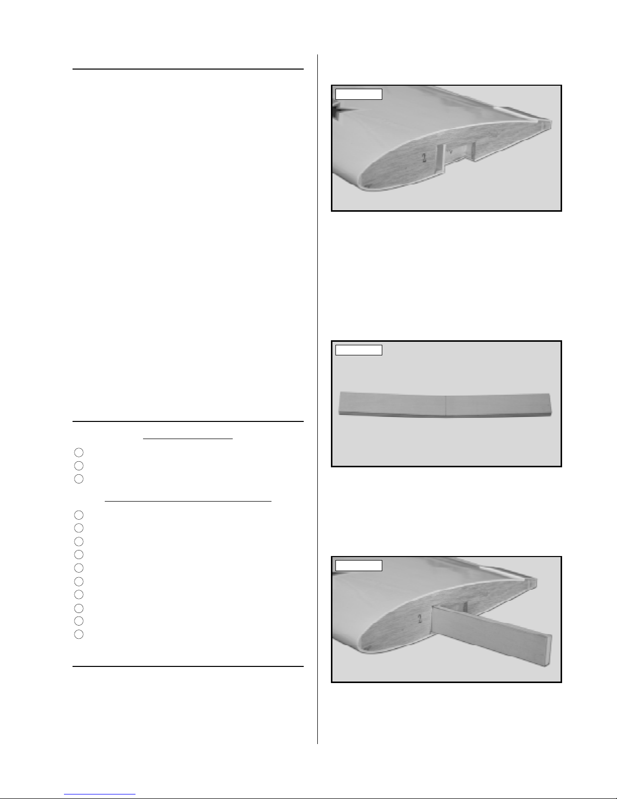
q 4) Test fit both of the wing halves together with
the dihedral brace temporarily installed (without using glue.) Look carefully at the center section joint:
the wing halves should fit together tight with little or
no gaps in the joint. See photo # 4 below.
q 10) Mix a generous amount of Kwik Bond 30
Minute Epoxy. Apply a thin layer of epoxy to the
exposed half of the dihedral brace, the inside of the
second wing half, and the entire surface of both root
ribs. Make sure to use enough epoxy to fill any gaps.
Photo # 4
q 5) If the center section joint is not tight, remove
the wing halves and the dihedral brace, and lightly
sand the edges and tips of the brace. T est fit the wing
halves together with the dihedral brace installed again
and repeat until you are satisfied with the fit. Once
you are satisfied with the fit, remove the wing halves
and the dihedral brace.
It is important that the wing halves fit together
?
properly. The better the fit, the stronger the center
section joint will be.
q 6) Following the instructions on the packaging,
mix up a generous amount of Kwik Bond 30 Minute
Epoxy. Mix the epoxy for about 1 minute. This will
ensure that both parts are thoroughly incorporated.
q 7) Working with only one wing half for now,
apply a thin layer of epoxy inside the plywood dihedral brace box and to only half of the dihedral brace.
Make sure to cover the top and bottom, as well as the
sides, and use enough epoxy to fill any gaps.
q 8) Slide the dihedral brace into the wing half
up to its centerline. Remove any excess epoxy before it dries using a paper towel and rubbing alcohol.
Allow the epoxy to fully cure before proceeding.
JOINING THE WING HALVES
q 9) Once the epoxy has fully cured, trial fit both
wing halves together again to double check that the
wing halves still fit together properly.
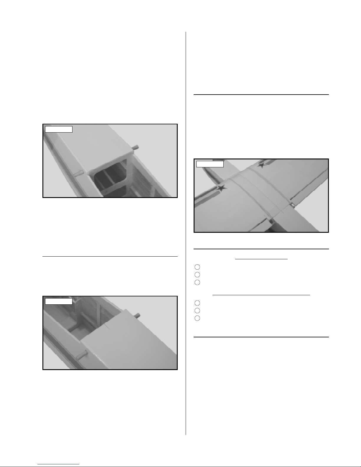
q 11) Slide the two wing halves together and carefully align them at both the leading and trailing edges.
Wipe away any excess epoxy using a paper towel
and rubbing alcohol and use several pieces of masking tape to hold the two wing halves aligned until the
epoxy fully cures. See photo # 5 below.
Photo # 5
q 12) Once the epoxy has fully cured, doublecheck the center section joint. If any gaps are present,
mix a small amount of Kwik Bond 30 Minute Epoxy
and carefully fill any remaining gaps. Remove any
excess epoxy using a paper towel and rubbing alcohol, and allow it to thoroughly cure.
WING INSTALLATION
PARTS REQUIRED
1
q {1} Fuselage w/Pushrod Housings
16
q {1} 1/4 x 6 Hardwood Dowel
17
q {1} 1/4 x 5-1/2 Hardwood Dowel
TOOLS AND SUPPLIES REQUIRED
1
q Kwik Bond Thin C/A
7
q Excel Modeling Knife
15
q 12” Straight Edge Ruler
20
q Pen or Pencil
INSTALLING THE WING DOWELS
q 1) Using a modeling knife, carefully remove the
covering from over the two predrilled wing hold down
holes in front of the wing saddle. One hole is located on each side of the fuselage 5/8” behind the
front of the windshield and 1” down from the top of
the fuselage.
12
Page 13
q 2) Using a modeling knife, carefully remove the
covering from over the two predrilled wing hold down
holes in back of the wing saddle. One hole is located
on each side of the fuselage 5/8” behind the wing
saddle and 5/8” down from the top of the fuselage.
q 3) Slide the 6” long hardwood dowel through
the two front holes and the 5-1/2” long hardwood
dowel through the two back holes. Align the dowels
so both ends of each dowel protrude equal amounts
from the fuselage sides. See photo # 6 below.
Photo # 6
q 4) When satisfied with the fit of both dowels,
apply about six drops of Kwik Bond Thin C/A to
each of the four joints where the dowels and fuselage sides meet. Allow the glue to fully cure before
proceeding.
ALIGNING THE WING
q 5) Using a ruler and a pen, locate the centerline of the fuselage, at both the front and the back of
the wing saddle and place one mark at each location. See photo # 7 below.
Photo # 7
q 6) Place the wing onto the wing saddle. The
joint where the two wing halves were glued together
is considered the centerline of the wing. Align the
centerline of the wing at both the front and the rear
of the wing saddle with the two centerline marks you
made on the fuselage.
MOUNTING THE WING
q 7) Using a couple of # 64 rubber bands, temporarily secure the wing to the fuselage. To properly
install the rubber bands, hook one over one side of
the front wing hold down dowel, carefully pull it back
over the wing and hook it over the rear hold down
dowel on the same side. Install two rubber bands on
each side for now. See photo # 8 below.
Photo # 8
HORIZONTAL STABILIZER
PARTS REQUIRED
4
q {1} Horizontal Stabilizer w/Elevator & Hinges
47
q {4} 3mm x 16mm Machine Screws
48
q {4} 3mm Flat Washers
TOOLS AND SUPPLIES REQUIRED
6
q # 2 Phillips Head Screwdriver
7
q Excel Modeling Knife
15
q 12” Straight Edge Ruler
These two centerline marks will help you align
?
the wing when you install it onto the fuselage. You
may wish to make these marks in permanent ink so
you can align the wing correctly each time you install it onto the fuselage. This will ensure the wing is
aligned properly every time you fly the airplane.
MOUNTING THE HORIZONTAL STABILIZER
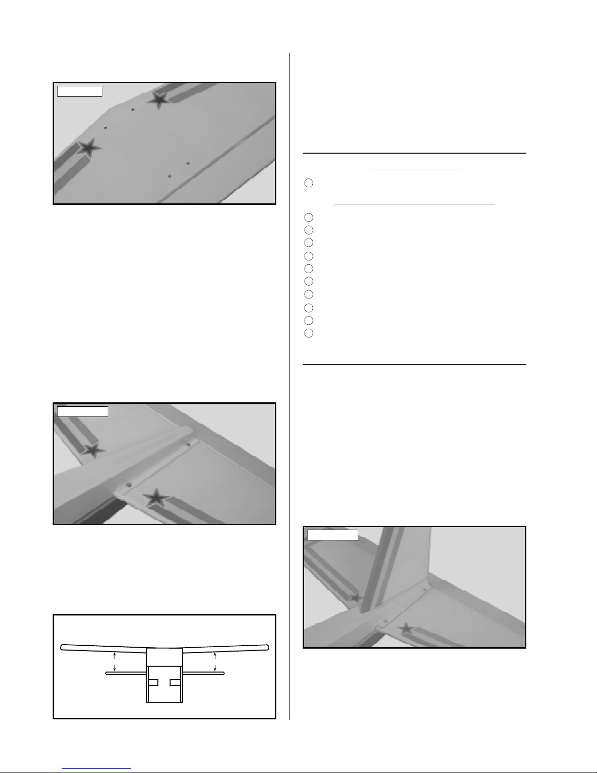
q 1) Using a modeling knife, remove the covering from over the four predrilled holes in the upper
stabilizer mounting platform on the fuselage.
The holes are located directly above the four
?
blind nuts preinstalled in the lower mounting platform.
q 2) Using a modeling knife, remove the covering from over the four predrilled mounting holes in
the stabilizer. Two holes are located 3/4” in front of
13
Page 14
the trailing edge and two holes are located 5-1/2” in
front of the trailing edge. See photo # 9 below.
Photo # 9
q 3) Slide the horizontal stabilizer into the stabilizer mounting slot. Align the four predrilled holes
in the stabilizer with the four predrilled holes in the
upper mounting platform.
q 4) Slide one 3mm flat washer onto each of the
four 3mm x 16mm machine screws.
q 5) Thread each of the four machine screws into
the upper mounting platform, through the stabilizer
and into the four blind nuts installed in the lower
mounting platform. Using a # 2 phillips screwdriver,
tighten each of the machine screws evenly and securely. See photo # 10 below.
If the stabilizer is not level with the wing, loosen
?
the four machine screws and slide a thin shim under
the low side of the stabilizer. Retighten the screws
and check the alignment once more. Repeat this procedure until you are satisfied that the alignment is
correct.
VERTICAL STABILIZER
PARTS REQUIRED
5
q {1} Vertical Stabilizer w/Rudder & Hinges
TOOLS AND SUPPLIES REQUIRED
3
q Kwik Bond 30 Minute Epoxy
7
q Excel Modeling Knife
15
q 12” Straight Edge Ruler
18
q Masking Tape
20
q Pen or Pencil
21
q Builders Triangle
22
q Paper Towels
23
q Rubbing Alcohol
24
q NHP Epoxy Mixing Sticks
25
q NHP Epoxy Mixing Cups
ALIGNING THE VERTICAL STABILIZER
q 1) Remove the rudder from the vertical stabilizer and set it aside for now.
Photo # 10
q 6) Install the wing onto the fuselage and hold it
securely in place using four # 64 rubber bands. Now
check to ensure that the horizontal stabilizer is aligned
with the wing. When viewed from the front, the horizontal stabilizer should be level with the wing. See
figure # 1 below.
Figure # 1
A
A-1
A = A-1
q 2) Using a modeling knife, remove the covering from over precut mounting slot in the top of the
fuselage. The slot is 5/16” wide and 4-1/2” long.
q 3) Slide the mounting tab in the vertical stabilizer down into the slot in the fuselage. The trailing
edge of the stabilizer should be even with the back
edge of the fuselage. See photo # 11 below.
Photo # 11
q 4) While holding the vertical stabilizer firmly
in place, use a pen and draw a line on each side of it
where it meets the top of the fuselage. Also draw an
outline on top of the fuselage where it and vertical
stabilizer touch.
14
Page 15

q 5) Remove the vertical stabilizer. Using a
modeling knife, carefully remove the covering from
below the lines you drew. Also remove the covering from the bottom edge of the stabilizer and from
inside the outline you drew on top of the fuselage.
See photo # 12 below.
Photo # 12
When cutting through the covering material to
?
remove it, cut with only enough pressure to only cut
through the covering itself. Cutting down into the
balsa may weaken the structure.
CONTROL SURFACE HINGING
TOOLS AND SUPPLIES REQUIRED
1
q Kwik Bond Thin C/A
3
q Kwik Bond 30 Minute Epoxy
7
q Excel Modeling Knife
16
q Scissors
17
q Waxed Paper
24
q NHP Epoxy Mixing Sticks
25
q NHP Epoxy Mixing Cups
HINGING THE AILERONS
q 1) Remove the ailerons and hinges from the
wing. Locate the four precut hinge slots in the trailing edge of each half of the wing and the leading
edge of each aileron.
q 2) Using a modeling knife, carefully remove any
excess covering from over each of the hinge slots in
the ailerons and the wing.
q 6) Set the vertical stabilizer back into place and
realign it. Now, using a builder's triangle, check to
ensure that the vertical stabilizer is aligned 90º to the
horizontal stabilizer. See figure # 2 below.
Figure # 2
90º
MOUNTING THE VERTICAL STABILIZER
q 7) Once you are satisfied that the vertical stabilizer is aligned correctly, mix up a generous amount
of Kwik Bond 30 Minute Epoxy . Apply a thin layer
to the mounting slot in the fuselage and to the sides
and bottom of the vertical stabilizer. Also, apply a
thin layer of epoxy to the top of the fuselage.
q 8) Set the vertical stabilizer into place and realign it. Hold the stabilizer in place with masking
tape and double check all of your measurements once
more before the epoxy cures. Remove any excess
epoxy using a paper towel and rubbing alcohol.
Allow the epoxy to fully cure before proceeding.
q 3) Test fit four C/A hinges into the hinge slots
in one aileron. Each hinge should be inserted far
enough into the slots so that the centerline of the
hinges are flush with the leading edge of the aileron.
If the hinges cannot be inserted deeply enough, use a
modeling knife and carefully cut the hinge slots
deeper. See photo # 13 below.
Photo # 13
q 4) W ith each of the hinges centered in the hinge
slots, apply 3-4 drops of Kwik Bond Thin C/A to the
joint where the hinges and the ailerons meet. Allow
a few seconds between drops for the C/A to wick
into the hinges, then turn the aileron over and repeat
this procedure on the other side of each hinge. Allow the C/A to dry for about 10 minutes before
proceeding.
q 5) Using a pair of scissors, cut out a 1-1/2” x
2-1/4” piece of waxed paper. Working with one
15
Page 16

wing half for now, slide the waxed paper between
the aileron torque rod and the trailing edge of the
wing. See photo # 14 below.
Photo # 14
q 10) Repeat steps # 3 - # 9 to install the second
aileron onto the other half of the wing.
HINGING THE ELEVATOR
q 11) Remove the elevator and hinges from the
horizontal stabilizer. Locate the four precut hinge
slots in the trailing edge of the horizontal stabilizer
and the leading edge of the elevator.
q 12) Using a modeling knife, carefully remove
any excess covering from over the hinge slots in both
the elevator and the stabilizer.
The waxed paper will prevent epoxy from get-
?
ting behind the torque rod and gluing it to the trailing
edge of the wing.
q 6) Using a modeling knife, carefully remove
the covering from over the predrilled hole and the
precut groove in the leading edge of the aileron. See
photo # 15 below.
Photo # 15
q 7) Mix up a small quantity of Kwik Bond 30
Minute Epoxy. Apply a thin layer of epoxy to the
aileron torque rod and pack epoxy into the predrilled
hole and the precut groove in the leading edge of
the aileron.
q 8) Slide the aileron and its hinges into the hinge
slots in the trailing edge of the wing, making sure
that the torque rod is firmly seated in the leading edge
of the aileron. Adjust the aileron so the tip doesn't
rub against the inside of the wing tip.
q 13) Test fit four C/A hinges into the hinge slots
in the elevator. Each hinge should be inserted far
enough into the slots so that the centerline of the hinges
are flush with the leading edge. If the hinges cannot
be inserted deep enough, use a modeling knife and
carefully cut the hinge slots deeper.
q 14) W ith each of the hinges centered, apply 3-4
drops of Kwik Bond Thin C/A to the joint where the
hinges and the elevator meet. Allow a few seconds
between drops for the C/A to wick into the hinges,
then turn the elevator over and repeat this procedure
on the other side. Allow the C/A to dry for about 10
minutes before proceeding.
q 15) Slide the elevator and its hinges into the
precut hinge slots in the trailing edge of the stabilizer. Adjust the elevator so that the tips do not rub
on the inside edges of the stabilizer tips.
q 16) W ith the elevator tight against the stabilizer,
rotate the elevator down about 45º. Apply 3-4 drops
of Kwik Bond Thin C/A to the exposed area of each
hinge. Turn the fuselage over and repeat for the other
side of the hinges. Allow the C/A to cure for about
10 minutes. Once cured, the elevator may be stiff
and difficult to move. This is normal. Gently move
it up and down about five to ten times to free it up.
HINGING THE RUDDER
q 9) With the aileron tight against the wing, rotate the aileron down about 45º. Apply 3-4 drops of
Kwik Bond Thin C/A to the exposed area of each
hinge. Turn the wing over and repeat for the other
side of the hinges. Allow the C/A and epoxy to fully
cure. Once cured, the aileron may be stiff and difficult to move. This is normal. Gently move the aileron
up and down about five to ten times to free it up.
16
q 17) Remove the rudder and hinges from the vertical stabilizer. Locate the two precut hinge slots in
the trailing edge of vertical stabilizer and the leading
edge of the rudder.
q 18) Using a modeling knife, carefully remove
any excess covering from over the hinge slots in both
the rudder and the stabilizer.
Page 17

q 19) Test fit two C/A hinges into the hinge slots
in the rudder. Each hinge should be inserted far
enough into the slots so that the centerline of the
hinges are flush with the leading edge. If the hinges
cannot be inserted deeply enough, use a modeling
knife and carefully cut the hinge slots deeper.
q 20) W ith each of the hinges centered, apply 3-4
drops of Kwik Bond Thin C/A to the joint where the
hinges and the rudder meet. Allow a few seconds
between drops for the C/A to wick into the hinges,
then turn the rudder over and repeat this procedure
on the other side. Allow the C/A to dry for about 10
minutes before proceeding.
q 21) Slide the rudder and its hinges into the precut hinge slots in the trailing edge of the stabilizer.
Adjust the rudder so that the tip does not rub against
the inside edge of the stabilizer tip.
q 22) With the rudder tight against the stabilizer,
rotate the rudder to the right about 45º. Apply 3-4
drops of Kwik Bond Thin C/A to the exposed area
of each hinge. Turn the fuselage over and repeat
for the other side of the hinges. Allow the C/A to
cure for about 10 minutes. Once cured, the rudder
may be stiff and difficult to move. This is normal.
Gently move it back and forth about five to ten times
to free it up.
back from the front edge of the firewall. The slot is
3/8” wide and 4” long.
q 2) Insert the 90º bend in each main gear wire
into the two predrilled holes in the mounting slot.
Push the wires down firmly until they are flush with
the bottom of the fuselage. See photo # 16 below.
Photo # 16
q 3) The two wires are held in place using two
metal landing gear straps and four 3mm x 12mm wood
screws. Each strap should be placed 7/8” in from the
fuselage sides. See photo # 17 below.
Photo # 17
MAIN LANDING GEAR
PARTS REQUIRED
6
q {2} Prebent Main Gear Wires
7
q {2} 75mm Diameter Wheels w/5mm Axle Hubs
8
q {2} Metal Landing Gear Straps
9
q {4} 3mm x 12mm Wood Screws
10
q {2} 5mm Nylon Spacers
11
q {2} 5mm Wheel Collars
12
q {2} 3mm x 6mm Machine Screws
TOOLS AND SUPPLIES REQUIRED
6
q # 2 Phillips Head Screwdriver
7
q Excel Modeling Knife
10
q Electric or Hand Drill
12
q 5/64” Drill Bit
15
q 12” Straight Edge Ruler
20
q Pen or Pencil
INSTALLING THE MAIN GEAR WIRES
q 1) Using a modeling knife, remove the covering from over the main gear mounting slot located in
the bottom of the fuselage. The slot is located 12-1/2”
q 4) Using the landing gear straps as a guide, mark
the locations of the four mounting screw pilot holes
onto the fuselage.
q 5) Remove the straps. Using a drill with a 5/64”
drill bit, drill four pilot holes through the fuselage at
the marks you made.
q 6) Install the two metal landing gear straps using four 3mm x 12mm wood screws. Tighten the
screws completely using a # 2 phillips screwdriver.
See photo # 18 below.
Photo # 18
17
Page 18

INSTALLING THE MAIN GEAR WHEELS
q 7) Partially thread one 3mm x 6mm machine
screw into each of the two wheel collars. Working
with only one landing gear wire for now, push one
nylon spacer onto the axle until it won't go on any
further.
q 8) Slide one 75mm diameter wheel onto the
axle. Push it up against the nylon spacer, then slide
the wheel collar onto the axle, and push it up against
the wheel. Adjust the depth of the wheel collar until
the wheel spins without binding, then tighten the machine screw using a # 2 phillips screwdriver. See
photo # 19 below.
Photo # 19
flat spots ground into the wire. Slide the steering
arm onto the strut, aligning it with the flat spot just
above the coil. Hold the steering arm in place as
shown and tighten the machine screw firmly using a
# 2 phillips screwdriver. See photo # 20 below.
Photo # 20
q 3) Partially thread two 3mm x 6mm machine
screws into two wheel collars.
q 4) Slide one wheel collar onto the strut, aligning it with the flat spot just above the steering arm.
Hold it in place and tighten the machine screw using
a # 2 phillips screwdriver.
q 9) Repeat steps # 7 and # 8 to install the second
wheel assembly onto the opposite landing gear wire.
NOSE GEAR
PARTS REQUIRED
26
q {1} Prebent Nose Gear Strut
27
q {1} 75mm Diameter Wheel w/4mm Axle Hub
28
q {1} Nylon Steering Arm
29
q {1} 4mm Nylon Spacer
30
q {3} 4mm Wheel Collars
31
q {4} 3mm x 6mm Machine Screws
41
q {1} 1.5mm x 460mm Plain Wire w/Z-Bend
TOOLS AND SUPPLIES REQUIRED
6
q # 2 Phillips Head Screwdriver
7
q Excel Modeling Knife
15
q 12” Straight Edge Ruler
INSTALLING THE NOSE GEAR STRUT
q 1) Partially thread one 3mm x 6mm machine
screw into the side of the nylon steering arm.
q 2) Look carefully at the upper portion of the
nose gear strut. You will notice that there are three
q 5) Using a modeling knife, remove the covering from over the steering pushrod exit hole in the
bottom of the fuselage. The hole is located 1” behind the firewall and 1” in from the left side of the
fuselage.
q 6) Insert the Z-bend in the steering pushrod
wire into the outermost hole in the steering arm.
See photo # 21 below.
Photo # 21
Install the pushrod wire so that the longer por-
?
tion of the wire comes out on the bottom of the
steering arm.
q 7) Carefully slide the plain end of the pushrod
wire into the nylon pushrod housing preinstalled in
the bottom of the fuselage.
18
Page 19

q 8) When the nose gear strut lines up with the
nylon mounting bracket, carefully push the strut down
into the bracket. See photo # 22 below.
Photo # 22
q 9) While holding the nose gear strut in place,
slide one wheel collar over the top of the strut and
up against the nylon bracket. Tighten the machine
screw firmly using a # 2 phillips screwdriver. See
photo # 23 below.
Photo # 23
FUEL TANK
PARTS REQUIRED
18
q {1} 360cc Molded Fuel Tank
19
q {3} Aluminum Tubes
20
q {1} Rubber Stopper
21
q {1} 20mm Diameter Front Plate
22
q {1} 17mm Diameter Back Plate
23
q {1} Silicon Fuel Tubing
24
q {1} Weighted Fuel Pickup
25
q {1} 3mm x 19mm Machine Screw
TOOLS AND SUPPLIES REQUIRED
4
q Silicon Sealer
6
q # 2 Phillips Head Screwdriver
15
q 12” Straight Edge Ruler
16
q Scissors
19
q 220 Grit Sandpaper
STOPPER ASSEMBLY
q 1) The fuel tank assembly incudes 3 different
length aluminum tubes. Discard the shortest of the
three tubes. It will not be used.
INSTALLING THE NOSE GEAR WHEEL
q 10) Partially thread one 3mm x 6mm machine
screw into one wheel collar. Push one nylon spacer
onto the axle until it won't go on any further.
q 11) Slide one 75mm diameter wheel onto the
axle. Push it up against the nylon spacer, then slide
the wheel collar onto the axle and push it up against
the wheel. Adjust the depth of the wheel collar until
the wheel spins without binding, then tighten the machine screw using a # 2 phillips screwdriver. See
photo # 24 below.
Photo # 24
q 2) Using 220 grit sandpaper carefully smooth
each end of the two tubes. This will prevent the fuel
line from being accidentally cut when it is installed.
q 3) Push the two aluminum tubes through the
rubber stopper. Slide the 20mm diameter front plate
over the tubes at the front of the stopper and slide the
17mm diameter rear plate over the tubes at the rear
of the stopper.
q 4) Using a ruler, measure the distance that the
two aluminum tubes protrude from the front of the
stopper assembly. This distance should be 3/8”. If it
is not, adjust the tubes by pushing them forward or
backward until you are satisfied with the alignment.
See photo # 25 below.
Photo # 25
19
Page 20

q 5) Carefully bend the longer of the two tubes
up at a 45º angle, being careful not to "kink" the tube.
When the stopper assembly is installed in the
?
tank, the top of the vent tube should rest inside the
bubble in the top of the tank.
q 10) When satisfied with the alignment of the
stopper assembly , tighten the machine screw using a
# 2 phillips screwdriver until the rubber stopper expands and seals the fuel tank opening. Do not
overtighten the screw. This could cause the front of
the tank to split. See photo # 28 below.
q 6) Secure one end of the silicon fuel tubing onto
the end of the weighted fuel pickup.
q 7) Slide the silicon fuel tubing, with the fuel
pickup attached, onto the end of the aluminum fuel
pickup tube. While holding the aluminum tube in
place, adjust the length of the silicon tube until the
fuel pickup is 4-3/8” back from the rear of the stopper assembly. See photo # 26 below.
Photo # 26
q 8) Push the 3mm x 19mm machine screw
through the center hole in the front of the stopper
assembly and partially thread it into the metal stopper backplate. See photo # 27 below.
Photo # 27
Photo # 28
INSTALLING THE FUEL TANK
q 11) Carefully apply a generous bead of silicon
sealer onto the front of the fuel tank.
q 12) Slide the fuel tank into position, making sure
that the stopper assembly fits into the predrilled hole
in the firewall. When aligned properly, the front of
the tank should be pushed firmly against the back of
the firewall and the back of the tank should rest in
the plywood cradle.
When installing the fuel tank, make sure that
?
the molded bubble in the top of the tank faces the top
of the fuselage.
INSTALLING THE STOPPER
q 9) Carefully push the stopper assembly into the
molded hole in the front of the fuel tank. Gently rotate the stopper assembly until the aluminum vent
tube rests inside the molded bubble in the top of the
tank.
If you have trouble seeing the vent tube, hold
?
the fuel tank assembly up to a bright light. This will
illuminate the inside of the tank.
20
q 13) Using a ruler and a pair of scissors, measure and cut out a 2-1/2” x 6” piece of Dubro Foam
Rubber. Fold the foam over itself once to double its
thickness. With the fuel tank aligned, wedge the foam
between the top of the fuel tank and the top of the
fuselage. See figure # 3 below.
Figure # 3
360 CC
This foam piece will hold the back of the tank
?
in place and the silicon sealer will prevent the tank
from moving backward.
Page 21

ENGINE INSTALLATION
PARTS REQUIRED
42
q {1} 1.5mm x 500mm Plain Wire w/Z-Bend
44
q {4} 4mm x 25mm Machine Screws
45
q {8} 4mm Flat Washers
46
q {4} 4mm Nylon Insert Nuts
49
q {1} Plastic Spinner Assembly
50
q {2} 2.5mm x 12mm Wood Screws
TOOLS AND SUPPLIES REQUIRED
5
q # 1 Phillips Head Screwdriver
6
q # 2 Phillips Head Screwdriver
7
q Excel Modeling Knife
8
q Needle Nose Pliers
10
q Electric or Hand Drill
13
q 11/64” Drill Bit
14
q 5/16” Drill Bit
15
q 12” Straight Edge Ruler
16
q Scissors
20
q Pen or Pencil
ALIGNING THE ENGINE
If you are using an engine that has a crankcase
?
dimension wider than the inside width of the hardwood rails, you can remove equal amounts of wood
from the inside edge of each rail. Remove small
amounts at a time until your engine fits properly, but
be careful not to remove too much material. A coping saw is best to use for this, but a sharp modeling
knife will work also.
q 4) When satisfied with the alignment, hold the
engine firmly in place and use a pencil to mark the
locations of the four mounting holes onto the hardwood rails.
q 5) Remove the engine. Using a drill with an
11/64” drill bit, drill four mounting holes through the
hardwood rails. See photo # 30 below.
Photo # 30
q 1) Using a drill with a 5/16” drill bit, enlarge
the hole in the plastic spinner backplate to fit your
engine's crankshaft.
Most .61 size engines use 5/16” diameter crank-
?
shafts. Please double check your engine before
drilling the backplate.
q 2) Remove the prop nut and washer from your
engine. Slide the backplate, followed by a 12 x 6
propeller, onto the crankshaft. Reinstall the prop
washer and prop nut and tighten the nut securely.
q 3) Set the engine onto the hardwood motor
mount rails and rotate the propeller so it is horizontal. To properly align the engine, use a ruler and
measure from the front of each fuselage side to the
back edge of the propeller. The measurement on the
left should be 3/8” and the measurement on the right
should be 1/4”. See photo # 29 below.
Photo # 29
q 6) Set the engine back into place and double
check that the holes in the engine mounting lugs line
up with the holes in the rails.
MOUNTING THE ENGINE
q 7) Slide one 4mm flat washer over each of the
four 4mm x 25mm machine screws. Slide each of
the screws through the motor mount lugs.
q 8) Turn the airplane on its side and slide one 4mm
flat washer onto each of the four machine screws, followed by a 4mm nylon insert nut. Tighten the screws
and nuts completely using a # 2 phillips screwdriver
and needle nose pliers. See photo # 31 below.
Photo # 31
21
Page 22

q 9) Install the carburetor onto your engine. If
your engine is equipped with a rear needle valve assembly, install that onto the engine as well. You will
need to use a modeling knife to cut a slot in the fuselage side to clear the rear needle valve assembly . See
photo # 32 below.
Photo # 32
q 15) Using a pair of scissors, cut each of the two
silicon fuel lines to the proper length and attach them
to the engine. The vent/pressure line connects to the
pressure nipple on the muffler. The fuel pickup line
connects to the fuel nipple on the carburetor, or the
rear needle valve assembly , if your engine is equipped
with one. See photo # 34 below.
Photo # 34
INSTALLING THE THROTTLE PUSHROD
q 10) Slide the plain end of the throttle pushrod
wire into the preinstalled nylon pushrod housing in
the firewall, directly behind the throttle arm.
q 11) Remove the throttle arm from the engine.
Install the Z-Bend in the pushrod wire into the hole
farthest out in the arm. Reattach the throttle arm to
the engine and tighten the throttle arm retaining nut
securely. See photo # 33 below.
Photo # 33
INSTALLING THE FUEL LINES
q 16) To fill the fuel tank, remove the silicon fuel
lines from both the carburetor and the muffler.
Direct the line from the muffler away from the
?
fuselage. This will prevent excess fuel from getting
onto the airplane.
q 17) Fill through the fuel pickup line and watch
for excess fuel coming from the vent line. When fuel
begins to come out of the vent line, the fuel tank is
full. Reattach the fuel lines to their proper locations.
INSTALLING THE SPINNER
q 18) Loosen the prop nut and turn the propeller
until it is centered between the four molded posts in
the backplate. See photo # 35 below.
Photo # 35
q 12) Using a pair of scissors, cut a 12” long piece
of silicon fuel tubing into two 6” long pieces.
q 13) Install one piece of fuel tubing to the fuel
pickup tube and one piece to the vent tube at the front
of the fuel tank.
q 14) Per your engine's instructions, install the
muffler onto the engine. Use a muffler gasket if your
engine provides one.
22
q 19) While holding the propeller aligned, tighten
the propeller nut firmly.
q 20) Test fit the spinner cone over the propeller .
Depending on the propeller you are using, the cone
may not fit over it. If this is the case, use a modeling
knife and carefully enlarge the two cutouts in the spinner cone.
Page 23

It is important that the spinner cone not touch
?
any part of the propeller when it is in place.
q 21) When satisfied with the fit, slide the spinner cone over the propeller, making sure that the
molded lip in the cone is seated in the molded groove
in the backplate. See photo # 36 below.
Photo # 36
Photo # 37
T o make it easier to install the servo tray, tem-
?
porarily remove the throttle pushrod wire. Reinstall
the pushrod wire after gluing the servo tray in place.
q 2) When satisfied with the fit, remove the servo
tray and apply a thick bead of Kwik Bond Thick C/A
to the tops of the two balsa support rails.
q 22) Turn the spinner cone until the two
molded holes in the cone line up with the two
molded mounting posts in the backplate. Using a
# 1 phillips screwdriver, install and tighten the two
2.5mm x 12mm wood screws to secure the spinner
cone into place.
Be careful not to overtighten the two screws.
?
You only want them tight enough to hold the spinner
cone in place. If you overtighten them, the spinner
cone may crack.
SERVO INSTALLATION
PARTS REQUIRED
14
q {2} Balsa Aileron Servo Tray Blocks
15
q {1} Plywood Aileron Servo Tray
43
q {1} Plywood Fuselage Servo Tray
TOOLS AND SUPPLIES REQUIRED
2
q Kwik Bond Thick C/A
5
q # 1 Phillips Head Screwdriver
7
q Excel Modeling Knife
10
q Electric or Hand Drill
11
q 1/16” Drill Bit
20
q Pen or Pencil
q 3) Set the servo tray back into place and realign
it. Hold the tray firmly in place until the glue fully
cures.
INSTALLING THE AILERON SERVO TRAY
Look carefully at the two balsa aileron servo
?
tray blocks. You will notice that the bottom of each
block is precut into the shape of a shallow "V". The
flat surface is glued to the servo tray.
q 4) Using Kwik Bond Thick C/A, glue the two
balsa aileron servo tray blocks to the bottom of the
aileron servo tray. The two blocks should be centered and glued flush with the ends of the tray. See
photo # 38 below.
Photo # 38
INSTALLING THE FUSELAGE SERVO TRAY
q 1) Test fit the plywood servo tray onto the two
preinstalled balsa support rails glued to the fuselage
sides. Position the tray so that the throttle servo cutout in the front of the tray is nearest the throttle
pushrod wire. See photo # 37 at top right.
q 5) T urn the wing upside down and set it on your
work table.
q 6) Set the aileron servo tray over the precut
servo cutout in the wing. T o align the servo tray properly, the cutout in the tray should be centered over
the cutout in the wing.
23
Page 24

q 7) When satisfied with the alignment, hold the
servo tray firmly in place. Using a pen, carefully
trace around the two balsa mounting blocks.
q 8) Remove the servo tray. Using a modeling
knife, carefully remove the covering from inside the
outlines. See photo # 39 below.
Photo # 39
q 9) Apply a thick bead of Kwik Bond Thick C/A
onto the bottom of the two balsa blocks. Set the servo
tray into place and realign it. Hold the tray in place
until the glue fully cures. See photo # 40 below.
q 11) Position three servos into the fuselage servo
tray , making sure that you run the servo wires below
the tray and out toward the front of the fuselage. Pay
close attention to the positions of the servo output
shafts. They should face the directions shown. See
photo # 41 below.
Photo # 41
T o make it easier in install the servos, position
?
the elevator and rudder servos first, then run their
servo wires out to the front of the fuselage. After
that you can position the throttle servo and its servo
wire more easily .
Photo # 40
INSTALLING THE SERVOS
q 10) Locate the four servos you intend to use for
the elevator, rudder/steering, throttle and aileron controls. Carefully install the four rubber grommets and
four brass collets onto each of the servo mounting
lugs. For proper vibration reduction, the brass collets should be inserted into the rubber grommets with
the flanges facing the bottom of the servo mounting
lugs. See figure # 4 below.
Figure # 4
q 12) Using a drill with a 1/16” drill bit, drill
twelve pilot holes through the servo tray , one for each
of the servo mounting screws (included with your
radio system). Using a # 1 phillips screwdriver, install and tighten the mounting screws to hold the
servos in place.
Drilling pilot holes through the servo tray will
?
make it easier to install the mounting screws.
q 13) Position the remaining servo into the aileron servo tray , noting the position of the servo output
shaft. It should face the trailing edge of the wing.
See photo # 42 below.
Photo # 42
24
Rubb er
Grommet
Brass Coll et
When installing the servo, make sure that you
?
run the servo wire out between the servo tray and the
wing.
Page 25

q 14) Using a drill with a 1/16” drill bit, drill four
pilot holes through the servo tray, one for each of the
mounting screws (included with your radio system).
Using a # 1 phillips screwdriver, install and tighten
the mounting screws to hold the servo in place.
Drilling pilot holes through the servo tray will
?
make it easier to install the mounting screws. Be
careful not to drill through the top of the wing!
Before starting the next few steps, please make
?
sure you have read and completely understood how
your radio control system operates.
q 4) Per your radio system guide, plug the battery
into the switch, the switch into the receiver, and the
throttle servo lead into the proper slot in the receiver.
Turn on the radio system.
THROTTLE PUSHROD
PARTS REQUIRED
37
q {1} Adjustable Servo Connector Assembly
TOOLS AND SUPPLIES REQUIRED
1
q Kwik Bond Thin C/A
5
q # 1 Phillips Head Screwdriver
6
q # 2 Phillips Head Screwdriver
9
q Wire Cutters
10
q Electric or Hand Drill
12
q 5/64” Drill Bit
INSTALLING THE SERVO CONNECTOR
q 1) Locate one plastic "4-point" servo horn that
came with your servo. Each of the arms should have
at least four holes in them.
q 2) Install one adjustable servo connector
through the forth hole out from the center of one of
the arms. When you thread on the nut, don't tighten
it completely. You don't want the connector loose,
but you do want it to be able to rotate without binding too much. See figure # 5 below .
Figure # 5
q 5) Check to ensure that the throttle servo output
shaft is moving in the correct direction. When the
throttle control stick on the transmitter is moved forward, from idle to full throttle, the servo output shaft
should rotate counterclockwise.
If the servo output shaft does not rotate coun-
?
terclockwise, flip the servo reversing switch on your
transmitter to change the direction. Please refer to
your radio system guide for more information on this
function.
q 6) Position the throttle stick and the throttle trim
lever on your transmitter at their lowest positions.
Slide the adjustable servo connector/servo horn assembly over the plain end of the throttle pushrod wire.
q 7) Push the carburetor barrel fully closed using your fingers. Angle the servo horn back about
45º from center and attach the servo horn to the servo
output shaft. The servo connector should be pointing toward the fuselage side. See photo # 43 below .
Photo # 43
You will have to enlarge the hole in the servo
?
arm using a 5/64” drill bit so that the servo connector will fit through without binding.
q 3) Apply a drop or two of Kwik Bond Thin C/A
to the connector nut and allow the glue to fully cure.
This will prevent the connector from loosening during flight.
q 8) With the carburetor barrel fully closed, use
a # 2 phillips screwdriver to tighten the machine
screw in the adjustable servo connector.
q 9) Using a # 1 phillips screwdriver, install and
tighten the servo arm retaining screw , provided with
your servo, to secure the servo horn into place.
25
Page 26

ADJUSTING THE THROTTLE LINKAGE
e
q 10) When your throttle linkage is adjusted properly, the carburetor barrel should be fully closed when
the throttle stick and the throttle trim lever are at their
lowest positions. Moving the throttle trim lever up
should open the carburetor barrel about 25%. Moving the throttle stick all the way forward should open
the throttle barrel completely. All of these movements should be done without any binding in the
linkage. Sometimes the servo will bind at the fully
closed and/or the fully opened throttle positions. If
this happens, and your radio is equipped with End
Point Adjustments (EPA), make those adjustments
using the transmitter (see your radio guide for further details). If your radio does not have this feature
you can still adjust the linkage manually. For more
travel, move the adjustable servo connector to a hole
farther out from the center of the servo horn. (You
will have to use a servo horn with five or more holes.)
For less travel, move the servo connector to a hole
closer to the center of the servo horn. Ideally, you
don't want the servo to bind while at idle or full
throttle.
ELEVATOR PUSHROD
PARTS REQUIRED
32
q {1} Nylon Control Horn
33
q {1} Nylon Backplate
34
q {2} 2mm x 20mm Machine Screws
35
q {2} Nylon Clevises
39
q {1} 4mm x 655mm Nylon Pushrod Tube
40
q {2} 2mm x 150mm Threaded Wires
TOOLS AND SUPPLIES REQUIRED
1
q Kwik Bond Thin C/A
5
q # 1 Phillips Head Screwdriver
7
q Excel Modeling Knife
8
q Needle Nose Pliers
9
q Wire Cutters
10
q Electric or Hand Drill
12
q 5/64” Drill Bit
15
q 12” Straight Edge Ruler
16
q Scissors
18
q Masking Tape
INSTALLING THE CONTROL HORN
q 2) To properly align the control horn, it should
be perpendicular to the hinge line and its centerline
should be 1-1/4” out from the fuselage side, at the
hinge line. The clevis attachment holes should be
located directly over the hinge line.
q 3) When satisfied with the alignment, use a drill
with a 5/64” drill bit, and the control horn as a guide,
and drill the two mounting holes through the elevator.
q 4) Set the control horn back into place and realign it. Push two 2mm x 20mm machine screws into
the base of the control horn and through the elevator.
See photo # 44 below.
Photo # 44
q 5) Place the nylon backplate onto the machine
screws, aligning the two holes in the backplate with
the two screws. Using a # 1 phillips screwdriver,
evenly tighten both machine screws to draw the
backplate into place. Be careful not to overtighten
the screws. You don't want to crush the wood.
INSTALLING THE PUSHROD
q 6) Slide the plain end of one 2mm x 150mm
threaded wire into one end of the nylon pushrod tube,
up to the wire's threads.
q 7) Thread the wire into the nylon tube until 5/8”
of wire extends past the end of the tube. Apply a
couple of drops of Kwik Bond Thin C/A to the wire
where it exits the nylon tube. Allow about 30 seconds for the glue to penetrate, then apply a couple
more drops. Allow the C/A to fully cure before proceeding. See figure # 6 below.
Figure # 6
Nylon Pushrod
Apply Glue
Here
q 1) Turn the fuselage over and position the
nylon control horn on the bottom, right side of
the elevator.
26
Threaded Wir
Page 27

It is important to glue the threaded wire into
?
the nylon pushrod tube. This will prevent the wire
from turning or pulling out during flight.
q 8) Repeat steps # 5 and # 6 to install the second
threaded wire in the opposite end of the pushrod tube.
Allow the glue to fully cure before proceeding.
After the glue has fully cured, pull on the
?
threaded wires to check that they are glued firmly in
place.
q 14) Using a modeling knife, remove the covering from over the elevator pushrod exit hole in the
back of the fuselage. The hole is located on the right
side of the fuselage, 8” in front of the elevator hinge
line and 3/4” up from the bottom of the fuselage.
q 15) Plug the battery into the switch and the
switch into the receiver. Plug the elevator servo lead
into the proper slot in the receiver and turn on the
radio system. Make sure the elevator control stick
and the elevator trim lever are centered.
q 9) Using a pair of scissors, cut two 1/4” long
pieces of silicon fuel tubing. Slide the tubing onto the
base of two nylon clevises. See photo # 45 below.
Photo # 45
q 10) Thread one nylon clevis 3/8” onto one end
of the pushrod assembly. Hold the wire with a pair
of pliers to help keep it from turning.
q 11) Locate a plastic "4-point" servo horn that
came with your servo. Each of the arms should have
at least four holes in it. Using a pair of wire cutters,
remove one of the plastic arms.
q 12) Using a drill with a 5/64” drill bit, enlarge
the fourth hole out from the center of the arm to the
left of the one you cut off.
q 13) Snap the clevis into the hole in the servo
arm. Slide the piece of silicon tubing up over the
clevis to secure it in place. See photo # 46 below.
q 16) Slide the elevator pushrod assembly into
the nylon pushrod housing, from inside the servo
compartment, until the servo horn lines up with the
servo output shaft. Attach the servo horn to the output shaft, making sure that the servo horn is centered.
See photo # 47 below.
Photo # 47
q 17) Use a couple of pieces of masking tape,
taped between the horizontal stabilizer and the elevator, to hold the elevator centered.
q 18) With the servo horn centered, carefully
thread the second nylon clevis onto the elevator pushrod wire until the pin in the clevis lines up with the
holes in the control horn. Use a pair of pliers to help
hold the wire and keep it from turning.
q 19) Snap the clevis into the fourth hole out from
the base of the control horn and slide the piece of
silicon tubing up over the clevis to secure it in place.
See photo # 48 below.
Photo # 46
Photo # 48
27
Page 28

q 20) Using a # 1 phillips screwdriver , install and
tighten the servo arm retaining screw, provided with
your servo, to secure the servo horn in place.
q 21) Remove the masking tape from the elevator and double check that both the elevator and the
elevator servo are still centered.
ADJUSTING THE ELEVATOR PUSHROD
q 22) With your radio system plugged in and
turned on, check the direction the elevator control
surface moves and the amount of control deflection.
T o do this pull back on the elevator stick. The elevator should move up. If it does not, flip the servo
reversing switch on your transmitter to change the
direction. (Refer to your radio guide for more information on this function.)
q 23) Pull back completely on the elevator control stick. While holding the control stick completely
back, use a ruler and measure the amount the trailing
edge of the elevator moves up. This measurement
should be 7/16”. See figure # 7 below.
Figure # 7
Elevator
7/16
7/16
Horizontal
Stabilizer
Note - Elevator moves the s ame amount
both up and down
RUDDER PUSHROD
PARTS REQUIRED
32
q {1} Nylon Control Horn
33
q {1} Nylon Backplate
34
q {2} 2mm x 20mm Machine Screws
35
q {2} Nylon Clevises
37
q {1} Adjustable Servo Connector Assembly
39
q {1} 4mm x 655mm Nylon Pushrod Tube
40
q {2} 2mm x 150mm Threaded Wires
TOOLS AND SUPPLIES REQUIRED
1
q Kwik Bond Thin C/A
2
q Kwik Bond Thick C/A
5
q # 1 Phillips Head Screwdriver
6
q # 2 Phillips Head Screwdriver
7
q Excel Modeling Knife
8
q Needle Nose Pliers
9
q Wire Cutters
10
q Electric or Hand Drill
12
q 5/64” Drill Bit
15
q 12” Straight Edge Ruler
16
q Scissors
18
q Masking Tape
INSTALLING THE CONTROL HORN
q 1) Position the nylon control horn on the lower,
left side of the rudder. To properly align the control
horn, it should be perpendicular to the hinge line and
its centerline should be 1” up from the bottom of the
rudder, at the hinge line. The clevis attachment holes
should be directly over the hinge line.
q 24) If the control surface deflection is more or
less than 7/16” it must be changed. If your radio is
equipped with End Point Adjustments (EPA), make
those adjustments using the transmitter. (Refer to your
radio guide for further details.) If your radio does not
have this feature, you can still make the adjustments
to the pushrod manually.
q 25) If the elevator is moving more than 7/16”,
move the clevis in one hole toward the center of the
servo horn to decrease the control deflection. If the
elevator is moving less than 7/16”, move the clevis
one hole closer to the base of the control horn to increase the control deflection. When adjusted
properly, the elevator should move 7/16” both up
and down.
28
q 2) When satisfied with the alignment, use a drill
with a 5/64” drill bit, and the control horn as a guide,
and drill the two mounting holes through the rudder.
q 3) Set the control horn back into place and realign it. Push two 2mm x 20mm machine screws into
the base of the control horn and through the rudder.
See photo # 49 below.
Photo # 49
Page 29

q 4) Place the nylon backplate onto the machine
e
screws, aligning the two holes in the backplate with
the two screws. Using a # 1 phillips screwdriver,
evenly tighten both machine screws to draw the
backplate into place. Be careful not to overtighten
the screws. You don't want to crush the wood.
INSTALLING THE PUSHROD
q 5) Slide the plain end of one 2mm x 150mm
threaded wire into one end of the nylon pushrod tube,
up to the wire's threads.
q 6) Thread the wire into the nylon tube until 5/8”
of wire extends past the end of the tube. Apply a
couple of drops of Kwik Bond Thin C/A to the wire
where it exits the nylon tube. Allow about 30 seconds for the glue to penetrate, then apply a couple
more drops. Allow the C/A to fully cure before proceeding. See figure # 8 below.
q 9) Thread one nylon clevis 3/8” onto one end
of the pushrod assembly. Hold the wire with a pair
of pliers to help keep it from turning.
q 10) Locate a plastic "4-point" servo horn that
came with your servo. Each of the arms should have
at least four holes in it. Using a pair of wire cutters,
remove one of the plastic arms.
q 11) Using a drill with a 5/64” drill bit, enlarge
the fourth hole out from the center of the arm to the
right of the one you cut off.
q 12) Snap the clevis into the hole in the servo
arm and slide the piece of silicon tubing up over the
clevis to secure it in place. See photo # 51 below.
Photo # 51
Figure # 8
It is important to glue the threaded wire into
?
the nylon pushrod tube. This will prevent the wire
from turning or pulling out during flight.
q 7) Repeat steps # 5 and # 6 to install the second
threaded wire into the opposite end of the pushrod
tube. Allow the glue to fully cure before proceeding.
After the glue has fully cured, pull on the
?
threaded wires to check that they are glued firmly in
place.
q 8) Using a pair of scissors, cut two 1/4” long
pieces of silicon fuel tubing. Slide the tubing onto the
base of two nylon clevises. See photo # 50 below.
Nylon Pushrod
Apply Glue
Here
Threaded Wir
q 13) Install one adjustable servo connector
through the second hole out from the center of the
servo arm directly opposite the nylon clevis. When
you thread on the nut, don't tighten it completely.
Y ou don't want the connector loose, but you do want
it to be able to rotate without binding too much. See
photo # 52 below.
Photo # 52
Photo # 50
You will have to enlarge the hole in the servo
?
arm using a 5/64” drill bit, so the servo connector
will fit through without binding.
29
Page 30

q 14) Apply a drop or two of Kwik Bond Thin
C/A to the connector nut and allow the glue to fully
cure. This will prevent the connector from loosening during flight.
q 21) Snap the clevis into the third hole out from
the base of the control horn and slide the piece of
silicon tubing up over the clevis to secure it in place.
See photo # 54 below.
q 15) Using a modeling knife, remove the covering from over the rudder pushrod exit hole in the back
of the fuselage. The hole is located on the top, left
side of the fuselage, 8” in front of the rudder hinge
line and 1/2” in from the fuselage side.
q 16) Plug the battery into the switch and the
switch into the receiver. Plug the rudder servo lead
into the proper slot in the receiver and turn on the
radio system. Make sure the rudder control stick and
the rudder trim lever are centered.
q 17) Slide the rudde r pushrod assembly into the
nylon pushrod housing, from inside the servo compartment, until the pushrod exits the top of the
fuselage.
q 18) Slide the adjustable servo connector/servo
horn over the end of the steering pushrod wire and
align the servo horn with the servo output shaft.
Attach the servo horn to the output shaft, making sure
that the servo horn is centered. See photo # 53 below.
Photo # 53
Photo # 54
q 22) W ith the rudder servo horn centered, center
the nose gear strut. When satisfied with the alignment, use a # 2 phillips screwdriver and tighten the
machine screw in the adjustable servo connector.
q 23) Using a # 1 phillips screwdriver , install and
tighten the servo arm retaining screw , provided with
your servo, to secure the servo horn in place.
q 24) Remove the masking tape from the rudder
and double check that the rudder, the rudder servo
and the nose gear strut are all still centered.
ADJUSTING THE RUDDER PUSHROD
q 25) With your radio system plugged in and
turned on, check the direction the rudder control surface moves and the amount of deflection. T o do this
push right on the rudder stick. The rudder should
move right. Look at the nose gear, too. It should
move right, as well. If they do not, flip the servo
reversing switch on your transmitter to change the
direction. (Refer to your radio guide for more information on this function.)
q 19) Use a couple of pieces of masking tape,
taped between the vertical stabilizer and the rudder,
to hold the rudder centered.
q 20) With the servo horn centered, carefully
thread the second nylon clevis onto the rudder pushrod until the pin in the clevis lines up with the holes
in the control horn. Use a pair of pliers to help hold
the wire and keep it from turning.
30
q 26) Push right completely on the rudder stick.
While holding the control stick fully right, use a ruler
and measure the amount the trailing edge of the rudder moves right. This measurement should be 1/2”.
See figure # 9 below.
Figure # 9
Rudder
1/2
1/2
Vertical
Stabilizer
Note - Rudder moves the same amount
both right and left
Page 31

q 27) If the control surface deflection is more or
less than 1/2” it must be changed. If your radio is
equipped with End Point Adjustments (EPA), make
those adjustments using the transmitter. (Refer to your
radio guide for further details.) If your radio does not
have this feature, you can still make the adjustments
to the pushrod manually.
q 28) If the rudder is moving more than 1/2”, move
the clevis in one hole toward the center of the servo
horn to decrease the control deflection. If the rudder
is moving less than 1/2”, move the clevis one hole
closer to the base of the control horn to increase the
control deflection. When adjusted properly , the rudder should move 1/2” both right and left.
AILERON PUSHRODS
PARTS REQUIRED
35
q {2} Nylon Clevises
36
q {2} Nylon Snap Keepers
38
q {2} 2mm x 120mm Threaded Wires w/L-Bends
TOOLS AND SUPPLIES REQUIRED
5
q # 1 Phillips Head Screwdriver
8
q Needle Nose Pliers
9
q Wire Cutters
10
q Electric or Hand Drill
12
q 5/64” Drill Bit
15
q 12” Straight Edge Ruler
16
q Scissors
18
q Masking Tape
q 3) Using a 5/64” drill bit, enlarge the third hole
out from the center of the arm to the right of the one
you cut off. Do the same in the arm directly opposite
the first one.
q 4) Insert the L-bends in the two 2mm x 120mm
aileron pushrod wires down through the two holes.
Place a nylon snap keeper over each wire to hold them
securely to the servo arms. See photo # 55 below.
Photo # 55
q 5) Using a pair of scissors, cut two 1/4” long
pieces of silicon fuel tubing. Slide the tubing onto the
base of two nylon clevises. See photo # 56 below.
Photo # 56
INSTALLING THE PUSHRODS
q 1) Two nylon adjustable control horns have
been partially threaded onto the two aileron torque
rods. Carefully thread the control horns into their
final positions. They should both be flush with the
tops of the torque rods. See figure # 10 below.
Figure # 10
q 2) Locate a plastic "4-point" servo horn that
came with your servo. Each of the arms should have
at least four holes in it. Using a pair of wire cutters,
remove one of the arms.
q 6) Plug the battery into the switch and the switch
into the receiver. Plug the aileron servo lead into the
proper slot in the receiver and turn on the radio system. Make sure the aileron control stick and aileron
trim lever are centered.
q 7) Attach the servo horn onto the aileron
servo output shaft, making sure that the servo horn
is centered. See photo # 57 below.
Photo # 57
31
Page 32

q 8) Use a couple of pieces of masking tape, taped
between the wing tips and the ailerons, to hold the
ailerons centered.
Figure # 11
Aileron
3/8
q 9) Thread the two nylon clevises onto the
threaded ends of the two aileron pushrod wires until
the pin in each clevis lines up with the hole in each
adjustable control horn. Use a pair of pliers to hold
the wires and keep them from turning.
q 10) Snap the clevises into the adjustable control horns and carefully slide the pieces of silicon
tubing up over the clevises to secure them in place.
See photo # 58 below.
Photo # 58
q 11) Using a # 1 phillips screwdriver , install and
tighten the servo arm retaining screw, provided with
your servo, to secure the servo horn into place.
3/8
Wing
Note - Both ailerons should move the
same amount both up and down
q 15) If the control surface deflection is more or
less than 3/8” it must be changed. If your radio is
equipped with End Point Adjustments (EPA), make
those adjustments using the transmitter . (Refer to your
radio guide for further details.) If your radio does not
have this feature, you can still make the adjustments
to the pushrods manually.
q 16) If the ailerons are moving more than 3/8”,
move both snap keepers in one hole towards the center of the servo horn to decrease the control deflection.
If the ailerons are moving less than 3/8”, thread both
adjustable control horns down about 1/4”. This will
increase the control deflection. When adjusted properly, both ailerons should move 3/8” both up and
down.
FINAL ASSEMBLY
q 12) Remove the masking tape from both ailerons
and double check that both ailerons, and the aileron
servo, are still centered.
ADJUSTING THE AILERON PUSHRODS
q 13) With your radio system plugged in and
turned on, check the direction the aileron control surfaces move and amount of deflection. To do this,
push right on the aileron control stick. The aileron
on the right side of the wing should move up and the
aileron on the left side should move down (looking
at the wing right side up, from the rear). If they do
not, flip the servo reversing switch on your transmitter to change the direction. (Refer to your radio guide
for more information on this function.)
q 14) Push right completely on the aileron stick.
While holding the control stick fully right, use a
ruler and measure the amount the trailing edge of
each aileron moves. This measurement should be
3/8”. See figure # 11 at top right.
PARTS REQUIRED
51
q {1} Decal Set
TOOLS AND SUPPLIES REQUIRED
5
q # 1 Phillips Head Screwdriver
7
q Excel Modeling Knife
9
q Wire Cutters
10
q Electric or Hand Drill
12
q 5/64” Drill Bit
16
q Scissors
INSTALLING THE SWITCH
q 1) Remove the two machine screws and faceplate from the switch harness that was included with
your radio system.
q 2) Using a modeling knife, carefully cut out the
switch hole, in the left side of the fuselage, using the
doubler on the inside of the fuselage side as a guide.
32
Page 33

q 3) Mount the switch using the faceplate and two
machine screws you removed previously. Use a # 1
phillips screwdriver to tighten the screws and secure
the switch in place. See photo # 59 below.
q 9) Using a drill with a 5/64” drill bit, drill a hole
through the left side of the fuselage, behind the battery and receiver mounts. Unwrap the receiver
antenna and feed it out through the hole.
Photo # 59
INSTALLING THE BATTERY & RECEIVER
q 4) Using a pair of scissors, cut out two 4” x 3-1/2”
pieces of Dubro Foam Rubber. Lay one of the pieces
of foam rubber on the fuselage floor between the two
battery and receiver mounts.
q 5) Place the battery pack onto the fuselage floor,
directly behind the forward mount.
q 6) Plug the three servo leads and the switch
lead into their proper slots in the receiver. Plug the
battery pack lead into its proper switch lead.
q 10) Using wire cutters, carefully make an antenna mount out of an extra servo horn. Cut the arm
into the shape shown. See figure # 12 below.
Figure # 12
Servo Horn
Modified Servo
q 11) Secure the antenna to the side of the vertical stabilizer using a small rubber band, a push pin,
and the modified servo arm. Use wire cutters to cut
the push pin shorter, so it doesn't stick through the
other side of the stabilizer. See photo # 61 below.
Photo # 61
Arm
Cut
Remove T his
Portion
W e also recommend using an aileron extension
?
lead to make it easier to plug in the aileron servo lead
when the wing is installed.
q 7) Set the receiver onto the fuselage floor, just
behind the battery pack. Place the second piece of
foam rubber over the battery and the receiver, making sure you leave the aileron extension lead
accessible.
q 8) Use two or three # 64 rubber bands, hooked
over both mounts, to hold the battery and receiver
firmly in place. See photo # 60 below .
Photo # 60
Adjust the modified servo arm so that the an-
?
tenna is not pulled too tight. You don't want to put
too much strain on it.
Do not cut off the excess antenna. Let the ex-
?
cess hang behind the airplane. Cutting the antenna
will greatly reduce the range of the receiver and could
cause you to lose control of the airplane.
APPLYING THE DECALS
q 12) Using a pair of scissors, carefully cut out
each of the decals along their outer edges.
q 13) Working with one decal at a time, remove
the protective backing and apply it to the airplane,
using the box top photographs as a reference for placement. Use a modeling knife to cut the window decals
out around the front wing dowel and temporarily remove the switch to make placement easier.
33
Page 34

BALANCING
CONTROL THROWS
TOOLS & SUPPLIES REQUIRED
15
q 12” Straight Edge Ruler
18
q Masking Tape
BALANCING THE RIGHT FLYER 60H
q 1) It is critical that your airplane be balanced
correctly. Improper balance will cause your airplane
to lose control and crash. The center of gravity is
located 4” back from the leading edge of the wing,
at the fuselage sides. This location is recommended
for initial test flying and trimming. There is a 3/8”
margin forward and a 1/2” margin aft. It is not recommended that the center of gravity be located any
farther back than 4-1/2”.
Balance the Right Flyer 60H ARF with the fuel
?
tank empty.
q 2) Mount the wing to the fuselage using six # 64
rubber bands per side. Using a couple of pieces of
masking tape, place them on the bottom of the wing,
4” back from the leading edge, at the fuselage sides.
q 1) We recommend setting up the Right Flyer
60H using the control throws that were recommended
in the pushrod installation steps. Those control throws
are suggested for initial test flying. If you haven't set
up the control throws yet, we have listed them here
again, along with a set of control throws recommended for aerobatics and/or experienced pilots.
Please refer back to these pages for the proper technique for adjusting the control throws.
TEST FLYING AND TRAINING
Ailerons: 3/8” up 3/8” down
Elevator: 7/16” up 7/16” down
Rudder: 1/2” right 1/2” left
AEROBATICS
Ailerons: 7/16” up 7/16” down
Elevator: 3/4” up 3/4” down
Rudder: 7/8” right 7/8” left
Do not use the Aerobatic
settings for Test Flying.
PREFLIGHT CHECK
q 3) Place your fingers on the masking tape and
carefully lift the plane. If the nose of the plane falls,
the plane is nose heavy. To correct this, move the
battery pack back in the fuselage just far enough to
bring the airplane into balance. If the tail of the plane
falls, the plane is tail heavy. To correct this, move
the battery pack forward only enough to bring the
airplane into balance. When balanced correctly, the
airplane should sit level or slightly nose down when
you lift it up with your fingers.
Once you have flown and trimmed the Right
?
Flyer 60H, the balance point (C.G.) can be moved
forward up to 3/8” or aft up to 1/2” to change the
flight performance. Moving the balance point back
will cause the airplane to be more responsive, but
less stable. Moving the balance point forward will
cause the airplane to be more stable, but less responsive. Do not fly the Right Flyer 60H beyond
the recommended balance range or an uncontrollable crash could result!
q 1) Completely charge the radio transmitter and
receiver batteries before your first day of flying.
q 2) Check every bolt and every glue joint in the
Right Flyer 60H to ensure that everything is tight and
well bonded. This should include all of the control
surface hinges as well.
q 3) Double check the balance of the airplane. Do
this with the fuel tank empty.
q 4) Check the control surfaces. They should all
move in the correct direction and not bind.
q 5) If your radio transmitter is equipped with dual
rate switches, double check that they are on the low
rate setting for your first few flights.
q 6) Check to ensure that the control surfaces are
moving the proper amount in both low and high rate
settings.
34
q 7) Check the receiver antenna. It should be fully
extended and not coiled up inside the fuselage.
Page 35

q 8) Properly balance the propeller. An out-ofbalance propeller will cause excessive vibration which
can lead to engine and/or airframe failure. To balance the propeller we recommend using the Prather
Prop Balancer. The part number is 520429.
SAFETY
The following are our guidelines for your safety and
the safety of others. Please read and understand these
safety guidelines before going out to the flying field
for the first time.
q 1) Do not test fly your model for the first time
without first having it safety-checked by an experienced modeler.
q 2) Do not fly your model higher than approximately 400 feet within 3 miles of an airport without
having an observer with you. The observer should
tell you about any full size aircraft in your vicinity
and you should always give the right of way to full
scale aircraft.
q 3) When flying at a flying field with established
rules, you should abide by those rules. You should
not deliberately fly your model in a reckless and/or
dangerous manner.
q 4) While flying, you should not deliberately fly
behind the flight line. If your model should inadvertently fly behind the flight line, you should change
course immediately.
q 5) Don't drink and fly. Consuming alcoholic
beverages prior to flying, or while you are flying, is
a big no-no.
q 6) You should complete a successful range
check of your radio equipment prior to each new
day of flying, or prior to the first flight of a new or
repaired model.
q 7) You should perform your initial turn after
takeoff away from the flightline and/or spectator area.
q 8) You should not knowingly operate your R/C
radio system within 3 miles of a preexisting model
club flying field without a frequency sharing agreement with that club.
ABC'S OF FLYING
If you've come this far, now you're ready to prepare for the maiden voyage of your new Right Flyer
60H. Before proceeding, we highly recommend
double checking all of your work. Make sure there
is no detail you missed and that you understand all
of the airplane's functions. We hope you find the
following sections helpful, making your first flights
successful.
Since you've chosen the Right Flyer 60H, you've
avoided the most common mistake beginners make:
choosing a high performance airplane like a P-51
Mustang or a F-16 jet as a trainer. Just as you wouldn't
learn to drive a car using an Indy car, new flyers
should learn to fly R/C airplanes using a trainer. The
second mistake new pilots make is not seeking out
the help of an experienced modeler. While it is certainly true that some people have learned to fly
without help, having the help of an experienced R/C
model pilot will help make those first few flights much
more successful and enjoyable. So, we highly recommend seeking out a club or a flying field near you.
Y ou'd be surprised just how many clubs there are that
help beginners.
Once at the field, even before removing your airplane from the car, introduce yourself to some of the
other pilots. Find out what safety procedures and
frequency control system is in place. In short, learn
and follow the field etiquette. Doing so will ensure
safe modeling for you and others. You will also be
able to find out who might be the right person to help
you learn to fly.
Sometimes, it is just impossible to find anyone
to help. In that case it would be wise to seek out
some additional information about flying. R/C Modeler, Harry Higley and Model Airplane News all
publish very good basic flight training books that
explain flying in greater depth. You may also wish
to seek out a computer simulator. Great Planes and
Dave Brown both make excellent flight simulators
that can be very effective at teaching the basic coordination of R/C flight.
If you do decide you have no choice but to learn
to fly on your own, choosing the place to fly your new
airplane is of the utmost importance. Select your potential flying field with the following considerations:
1) Look for a long, wide runway. The bigger it
is, the easier it is to find when landing. Optimum
sites are large grass fields and dry lake beds.
2) The fewer the ground obstructions the better! No close trees, small hills, large rocks or buildings
should be nearby.
35
Page 36

3) While R/C flying is generally safe, it can lead
to serious harm or injury . Do not try to fly your model
if there are any houses or people nearby.
4) The takeoff surface should be short grass,
hard packed dirt, concrete or asphalt. The surface
should be smooth and free from any small rocks or
holes. You don't want anything to interfere with the
plane as you taxi, takeoff and land.
Choosing the Right Flyer 60H as your first airplane greatly simplifies these activities. First, it
takes very little thrust to overcome the drag, so much
so that the airplane glides well with no power at all.
Second, the wing is a high lift design that easily
overcomes the weight, which means that the airplane
can fly very slowly.
Controlling the Right Flyer 60H
5) No high-lines, telephone lines or electrical
lines should be near the flying site. If your plane
accidentally does fly into wires of some kind do not
try to retrieve it yourself! Serious injury or even death
could result. Contact the local police or fire department. They can send somebody to help you retrieve
the airplane safely.
BASICS OF FLIGHT
To begin, you should know how the Right Flyer
60H operates. First, there are four forces operating
on a flying aircraft: Lift, Weight, Thrust and Drag.
The engine will create thrust to overcome the drag.
In times when the engine is off, gravity pulling the
plane down can act as thrust (how gliders work). The
wing flies through the air as a result of the thrust and
causes lift to overcome the weight of the aircraft.
Lift
Thrust
Flying is three dimensional, therefore, all aircraft
operate on three axis: roll, yaw and pitch. Roll is the
wing tips raising and lowering. Y aw is the nose moving from right to left. Pitch is the nose moving up
and down. Maintaining flight is the act of overcoming weight and drag with lift and thrust while properly
controlling all three axis.
Weight
Yaw
Roll
Drag
If you have never controlled any vehicle by radio control, then this step can be especially important.
Some of the basic coordination can be learned on the
ground by simply practicing taxiing the aircraft. First,
remove the wing and cover the open area of the fuselage, where the wing would normally go, with a thin
piece of cardboard. This will protect the radio equipment from engine exhaust.
Check the controls. Make sure the throttle and
steering are working properly . Start your engine, and
at low throttle try driving the airplane around on the
ground. A large, unused parking lot is especially good
for this practice. Remember, moving the stick to the
right or left is in relation to the airplane's right or left.
Keep practicing because it will take some getting used
to. Try figure 8's and rectangular patterns. Don't go
too fast! The Right Flyer 60H is not a car! This will
also give you a chance to make sure the nose gear
steering tracks straight. It may be necessary to adjust the steering linkage if it doesn't track straight.
Learn to control the throttle, too. Most flying
will be done at less than full throttle; however, takeoffs will be at full throttle and landings will be with
throttle at idle or completely off. So, get used to setting the throttle at different speeds.
If you can easily steer the airplane around on the
ground, it's time to take that experience and apply it
to flight. First, let's lay out the basic maneuvers that
will make up your training flights.
1) Takeoff
2) Climb-out
3) Level Flight
4) Standard Turns
5) Descent
6) Landing
36
Pitch
All flight is based on these few tasks. Here, we've
laid them out in the same order they will be during
flight. Learn these basics and you will soon fly your
Right Flyer 60H with great success. Now look at
each maneuver individually . Before flight, make sure
you are completely familiar with the functions of the
transmitter, including all controls and trim levers.
Page 37

Takeoff and climb-out require that the plane be
facing into the wind. Make small adjustments to the
rudder control stick to keep the plane tracking straight
as engine power is increased. Allow the airplane to
continue to roll on the ground until the airplane is
moving fast. Gently apply a small amount of up elevator to lift the nose. The wing will lift the plane
off the ground. At this point let off of the rudder and
use the ailerons to keep the wings level. Use the elevator to keep the nose up slightly. Allow the plane
to climb on its own. Climbing too fast will cause the
plane to pitch up and stop flying, and the nose will
drop rapidly. This is called a stall. If this happens,
allow the nose to drop slightly (which will give the
airplane more speed) and then apply a small amount
of up elevator to bring the nose level.
Once the airplane has reached 50 to 100 feet of
altitude, it is time to level the plane and then try a
turn. To level the plane, simply move the elevator
stick to neutral. Keep the wings level using the ailerons. If the plane still climbs slightly or turns, adjust
the trim levers on the transmitter until the airplane
flies straight with no stick input.
Now try a turn (before the airplane gets too far
away). To turn, apply aileron until the wing drops
about 15 degrees (or the wing tip is just below the
fuselage). As the wing drops, begin to apply up elevator. Up elevator will maintain the plane's altitude
and will hold it in the turn. To prevent the plane
from turning too steep, as soon as a good bank is
established, release the aileron control. Use only the
elevator to maintain altitude and hold the plane in
the turn. Once it has turned enough, apply opposite
aileron to level the wings. As this opposite aileron is
applied, slowly release the up elevator.
Now continue level flight, which will be a small
series of tiny corrections of elevator and aileron to
keep the plane straight and level. If you lost altitude
during the turn, this is a good time to climb out again.
Before the plane gets too far away, try another
turn. Continue making standard turns and keep the
airplane over the flying field.
The next maneuver will be descent. Usually , one
pairs descent with landing, but, in fact, most model
airplanes are constantly descending and climbing out.
Having the ability to perform a good controlled descent is important. To descend, simply throttle back
to about 1/4 throttle. As the throttle is reduced, allow the plane's nose to drop some.
The descent should be gentle, so let the nose drop
about 10 to 20 degrees. Keep the wing level unless a
turn is required. If you must turn, bank as usual to
start the turn but only hold about half of the normal
amount of up elevator you usually hold to maintain a
turn. In doing so, you will not slow the airplane too
much. When you've reached your desired altitude,
level the wings and add throttle as you add some up
elevator to level the plane.
The final maneuver will be landing. For your
first landing, the goal should be to get the plane down
anywhere on the field without hitting anything. Landings should always be made into the wind. Usually,
it is easiest to set up for a landing by making a landing approach. The first part of the landing approach
is the descent. Descend going with the wind (opposite of the direction you will be landing). Once you've
descended to an altitude of 30-50 feet, turn into the
wind. At this point level the wings, throttle back to
idle and allow the nose to drop to descend to the
ground without getting too slow. When the plane is
10 feet off the ground (just above eye level), apply
small amounts of up elevator to slow the descent and
to slow the plane. Remember to keep the wings level.
Now the plane should descend but it will seem like
the nose has not dropped much. If the plane doesn't
descend, allow the nose to drop a little. Just before
the plane touches down, apply some up elevator to
level the plane with the ground. Because the engine
is at idle (or off completely) the plane will still drop
and touch down.
Things to avoid
1) Stalling. Stalling is when the air stops flowing over the wing properly. For the Right Flyer 60H,
this only happens when the airplane is flying very slow .
A stall normally results in the nose dropping uncontrollably. If a stall does occur, allow the nose to drop,
which will increase the airspeed, then apply up elevator to level the plane. Remember not to pull too much
up elevator or the stall may occur again.
2) Radical Turns. Keeping the wings level or
making standard turns are big steps in preventing the
plane from getting out of control. If the plane seems
too fast or is getting into too steep a turn, try letting
all of the controls go to neutral, then reduce the throttle
and make corrections to level the wings and then level
the plane.
3) Overcontrolling. Most new pilots try to fly
like they are playing a video game. Most likely, you
will never need full stick movement for any
37
Page 38

correction. T ypically , you will need very little down
elevator as well. Remember to move the stick only
small amounts at a time. The radio control system
you are using is proportional, meaning the amount
you move the stick is in direct proportion to the
amount the control surface moves. Full deflection of
the control surfaces is typically reserved for correcting a major mistake or trying an aerobatic maneuver.
Planning the first flight
After reading through the maneuvers, you need
to plan your first flight. For your first flight, pick a
day that is clear and not windy . Too much wind will
complicate your first flight. Take the time to envision the flight path. The flight will, of course, begin
with take off and climb-out. Once a safe altitude has
been reached, make a turn down wind and continue
to climb. Level off at about 100 feet of altitude. Try
to perform a basic figure 8 pattern. Learn to make
small corrections to keep your plane pointed in the
direction you want it to fly. After 8 to 10 minutes,
begin your descent to land. Try to turn into the wind
to land. If your first landing gets the plane down in
one piece and is located somewhere on the flying
field, that's pretty good!
Picture yourself flying the plane before trying to
actually fly it. It may seem silly, but even professional pilots still review their maneuvers in their head
before flying. Military pilots use small hand held
models to help them picture their plane's movements.
Leave the plane's radio and engine off. Hold the
transmitter in your hand and set the airplane on the
ground, facing into the wind. Apply throttle and
imagine steering the model straight down the runway. Continue to imagine each one of the flight
maneuvers and what you have to do on the sticks to
keep the plane flying. Remember to pull back on the
stick for up elevator, and that turning the plane right
or left is in relation to the airplane, not to your right
or left. It helps to imagine yourself actually in the
cockpit while you're flying.
Before trying the first flight, check that the engine is running properly. Perform a range check as
described in your radio system guide and make sure
that the batteries have a full charge.
We hope this information will help you make those
first few flights successful.
Happy Landings!
GLOSSARY OF TERMS
Adjustable Connector: Connects to the servo arm.
The pushrod wire passes through the connector and
is held in place with a set screw. The screw can be
loosened to allow the pushrod wire to be adjusted to
the correct length.
Blind Nut: A special type of nut that is used when
you can reach to install or tighten a standard nut. A
blind nut has prongs that secure it into place.
C/A Glue: An acronym for Cyanoacrylate. It dries
very fast like "Super Glue". It comes in many different formulas for different uses.
Carburetor: By adjusting the high and low speed
needle valves, you can change the mixture and control the speed of the airplane.
Center of Gravity: Most commonly referred to as
the CG or balance point, it is the point at which the
airplane is in complete balance in all three axis.
Clevis: Part of the control system, either made out
of nylon or metal. It connects the pushrod wire to
the control horn mounted on the control surface.
Clevis Attachment Holes: The molded holes in the
control horn. The clevis attaches to these holes.
Control Horn: Part of the control system, the control horn is mounted to the control surface. It allows
the pushrod to be connected to the control surface.
Almost all control horns are adjustable to allow for
more or less control surface movement.
Covering: Material made out of vinyl or polyester.
Covering has heat sensitive adhesive that, when heated,
sticks to the wood frame of the airplane. The Right
Flyer 60H uses heat sensitive polyester covering.
Covering Iron: A small hand-held iron, usually
Teflon® coated. It is used to heat and apply covering material.
Dihedral: The upward angle of each wing half. Dihedral creates more stability which makes learning
to fly much easier.
38
Page 39

Dihedral Brace: Made out of plywood or alumi-
num, the dihedral brace strengthens the joint between
two wing sections.
Elevator: The elevator is the control surface on the
back of the airplane that moves up and down. This
surface controls pitch.
Pushrod Housing: A tube that is usually nylon. The
pushrod wire runs through the housing.
Receiver: The part of the radio system that receives
the signals from the transmitter.
Root Rib: The most inboard rib of any wing panel.
E.P .A.: An acronym for End Point Adjustments. This
is a feature found on newer radio systems that allows
you to electronically adjust the end-travel in servos.
Epoxy: A two part glue containing a resin and a
hardener. Epoxy is available in several drying times
and is stronger than C/A glue. Epoxy is used in high
stress areas such as joints of wing halves.
Expanded Scale Voltmeter: This device is used to
check the voltage of your receiver battery pack.
Foam Rubber: This material is used to dampen the
vibration caused by the engine. Doing this protects
your receiver and battery from damage.
Fuel Pickup: More commonly referred to as the
"clunk", the fuel pickup is weighted so that it can
move easily within the fuel tank.
Hinges: Usually made out of plastic or nylon, the
hinges connect the control surfaces to the stabilizers
or wing. They pivot, allowing the control surface to
move.
Rudder: The rudder is the control surface on the
back of the airplane that moves right and left. This
causes the nose of the airplane to yaw right and left.
Servo: The part of the radio system that produces
the movement necessary to move the control surfaces.
The servo includes a small motor, gears and a circuit
board.
Servo Horn: Made out of plastic or nylon, it attaches to the servo output shaft. The pushrod and/or
servo connector are then attached to the servo horn.
Servo Output Shaft: The final gear in the servo
gear train. It's the gear that the servo horn is attached to.
Servo Reversing: An option on almost all new radios, servo reversing allows you to change the
direction a servo rotates by just flipping a switch on
the transmitter.
Servo T ray: Usually made out of plywood, the servo
tray is the mounting base for the servos.
Horizontal Stabilizer: Mounted in the rear of the
airplane, the stabilizer works with the elevator to con-
trol pitch.
Landing Gear Strap: Usually made out of nylon
or aluminum, i t secures the landing gear wires to
the wing or fuselage.
Needle Valve: Sometimes referred to as the "mix-
ture screw", the needle valve meters the fuel/air
mixture of the engine.
Pushrods: They connect between the control sur-
face and the servo, transferring the movement of the
servo directly to the control surface.
Stall Speed: The speed at which air stops moving
fast enough over the surface of a wing to keep the
airplane flying.
Spinner: A term for the nose cone that covers the
propeller hub.
Threaded Pushrod: A length of wire that has threads
cut into one end of it. See Pushrods.
Transmitter: The part of the radio system that you
control. It transmits the control inputs to the receiver,
which transfers that information to the servos.
Continued on Next Page
Ü
39
Page 40

Trim Lever: A sliding lever on the transmitter that
allows you to make small adjustments to the control
surfaces from the transmitter.
Vent Tube: Commonly referred to as the pressure
tube, the vent tube is connected by the fuel line to the
muffler pressure nipple on the muffler. Removing
the vent tube during the fueling process allows excess fuel to come out of the tank.
Vertical Stabilizer: Mounted on the rear of the airplane, it works with the rudder to turn the airplane.
It also gives the airplane vertical stability.
Wing Saddle: This is the area formed by the fuselage sides that the wing is mounted to.
Z-Bend: This is a special bend made in the pushrod
wire. While it cannot improve your ability to make
adjustments, the Z-Bend is the most secure way to
attach the pushrod wire to the servo horn.
40
Page 41

41
Page 42

42
Page 43

PRPR
PR
PRPR
PRPR
PR
PRPR
Telling us what you like and don't like determines what model kits we make and how we make them. We
would appreciate it if you would take a few minutes of your time to answer the following questions about
this kit. Simply fold this form on the dotted lines, seal with tape and mail it to us. Do not use staples and
make sure our address faces out.
ODUCT EVODUCT EV
ODUCT EV
ODUCT EVODUCT EV
ODUCT EVODUCT EV
ODUCT EV
ODUCT EVODUCT EV
ALUALU
ALU
ALUALU
ALUALU
ALU
ALUALU
AA
TION SHEETTION SHEET
A
TION SHEET
AA
TION SHEETTION SHEET
AA
TION SHEETTION SHEET
A
TION SHEET
AA
TION SHEETTION SHEET
1) Kit: RIGHT FLYER 60H ARF
2) Where did you learn about this kit?
q Magazine Ads q Friend
q Hobby Shop q Other
q Internet
3) What influenced you the most to buy this kit?
q Magazine Ads q Price
q Type of Model q Box Art
q Recommendation q Other
q Internet
4) Did you have any trouble understanding the
written instructions? If yes, please explain.
q Yes q No
_____________________________________
_____________________________________
_____________________________________
_____________________________________
5) Did you have any trouble understanding any of
Cut Along Dotted Line
the photographs? If yes, please explain.
q Yes q No
_____________________________________
_____________________________________
_____________________________________
_____________________________________
6) Were any of the kit parts:
q Damaged q Wrong Size
q Missing q Wrong Shape
If you checked any of the boxes above, did you
contact our Customer Service Department to re
solve the problem?
q Yes q No
7) Was any of the assembly difficult for you? If
yes, please explain.
q Yes q No
_____________________________________
_____________________________________
_____________________________________
_____________________________________
8) What did you like most about this kit?
q Assembly Manual q Parts Fit
q Hardware Supplied q Price
q Other
_____________________________________
_____________________________________
_____________________________________
9) What did you like least about this kit?
q Assembly Manual q Parts Fit
q Hardware Supplied q Price
q Other
_____________________________________
_____________________________________
_____________________________________
10) Are you satisfied with the finished model? If
no, please explain.
q Yes q No
_____________________________________
_____________________________________
_____________________________________
_____________________________________
11) How does this kit compare to similar kits by
other manufacturers?
q Better Than q As Good
q Not as Good
Additional Comments: ______________________________________________________________
_________________________________________________________________________________
_________________________________________________________________________________
_________________________________________________________________________________
_________________________________________________________________________________
43
Page 44

Fold along dotted line
___________________________
___________________________
___________________________
(Return Address Here)
Post Office
will not
deliver
without
proper
postage
Global Hobby Distributors
Attn: Customer Care
18480 Bandilier Circle
Fountain Valley , CA. 92728-8610
Fold along dotted line
44
 Loading...