

Page 1
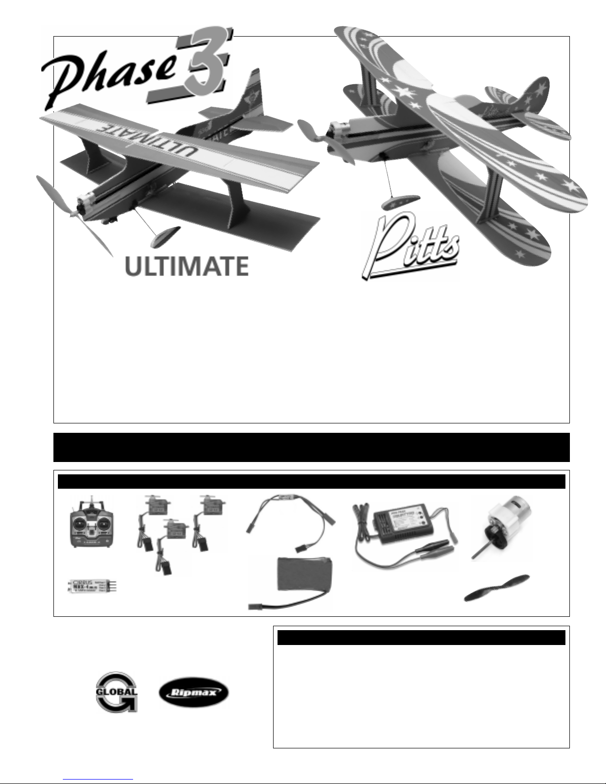
Phase3, the new choice in performance 3D profiles. This new selection of two biplanes for indoor or still-air use brings a fresh look to profile
lightweight foam aircraft. Each is made from a special foam laminate, which provides a strong structure that resists damage and can carry a
dramatic color scheme. By limiting the material to 4.5mm and by using a tissue-light surface to print on, we've managed to keep weight to an
absolute minimum. Unlike so many of these models, the Phase3 designs have a solid color scheme printed on all sides - no single-surface,
transparent colors here!
Each model has factory-installed carbon strip spars and fuselage stiffeners for strength, without the unsightly and heavier wood used in other
models. The undercarriage struts are also made from carbon and secured into molded plastic brackets on reinforced surfaces.
Assembly is simple and easy. You'll need a power system and radio gear. The Cirrus micro servos and receiver are the perfect choice for your
new Phase3 profile, although any lightweight equipment can be used. For the economy minded, we have 370 motors and gear boxes available.
For those who want more spirited performance, small outrigger-style brushless, direct drive motors with 2-3 LiPO cells perform perfectly.
THESE INSTRUCTIONS ARE FOR BOTH THE ULTIMATE AND THE PITTS. RECOMMENDED ITEMS FOR FLIGHT
AND THE RECOMMENDED ITEMS NECESSARY TO BUILD EACH AIRPLANE ARE THE SAME.
INSTRUCTIONS FOR ULTIMATE & PITTS PROFILES
RECOMMENDED ITEMS FOR FLIGHT - For the Recommended Brushless Power System, Please See Page # 2
Phase3 10A
Micro ESC
4 Channel or More
Transmitter
4-6 Gram Micro
Servos (3)
4 Channel or More
Micro Receiver
WattAge 2 Cell 1250mAH
LiPO Battery
The Phase3 Ultimate and Pitts Profile kits are distributed
exclusively in the USA by Global Hobby Distributors
and in the U.K. by Ripmax
All contents copyright © 2005 Global Hobby Distributors
Version V1.0 May 2005
Phase3 370 Motor
w/Gear Box
Quattro LiPO
Battery Charger
*We Don't Recommend Using a 3 Cell Battery
with the 370 Motor and Gear Box Recommended
Propeller to
Suit Power System
Specifications (Ultimate/Pitts)
●
Wing Span: 30.75in. (780mm) Both / 32.25in. (813mm) & 30.75in. (780mm)
●
Wing Area: 345 Square Inches (22.24dm2) / 332 Square Inches (21.42m2)
●
Length: 31 Inches (790mm) / 28.25 Inches (720mm)
●
Weight RTF: ~14 Ounces (400gr) / ~14 Ounces (400gr)
●
Wing Loading: 5 oz/sq.in. (15gr/dm2) / 5.5 oz/sq.in. (16.7gr/dm2)
●
Functions: Ailerons, Elevator, Rudder and Throttle
●
Radio Required: 4 Channel or More w/3 Micro Servos & Micro RX
●
Battery Required: 2 Cell 1250mAH LiPO
1
Kit Product Number (107012 Ultimate and 107011 Pitts)
Page 2
CUSTOMER SERVICE INFORMATION
If you should find a part missing or damaged, or have any questions about assembly, please contact us at the address below:
In the USA:
Global Services
18480 Bandilier Circle
Fountain Valley, CA 92708
Phone: (714) 963-0329
Fax: (714) 964-6236
Email: service@globalhobby.net
In the United Kingdom:
Ripmax LTD.
Ripmax Corner
Green Street
Enfield
EN3-7SJ
United Kingdom
Phone: +44 (0) 20 8282-7210
Fax: +44 (0) 20 8282-7500
Email: mail@ripmax.com
CHECK IT OUT! We urge you to come check out our website at http://globalservices.globalhobby.com. There you will find public message
boards frequented by other Phase3 product owners and the Phase3 support staff. This is a great place to learn about new products, get help
and suggestions for your current Phase3 products or just simply hang out and chat with people that share your same interests.
To enable us to better serve your needs, please include your email address with any correspondence you send to us. Your email
address will be added to our Customer Service Database so you will automatically receive free updates and tech notices for your
particular product. You will also receive repair status updates (if applicable) and other important information about your product
as it becomes available.
IMPORTANT INFORMATION ABOUT YOUR EMAIL ADDRESS
Global Hobby Distributors will not disclose the information it collects to outside parties. Global Hobby Distributors does not sell,
trade, or rent your personal information to others . Your privacy is important to us.
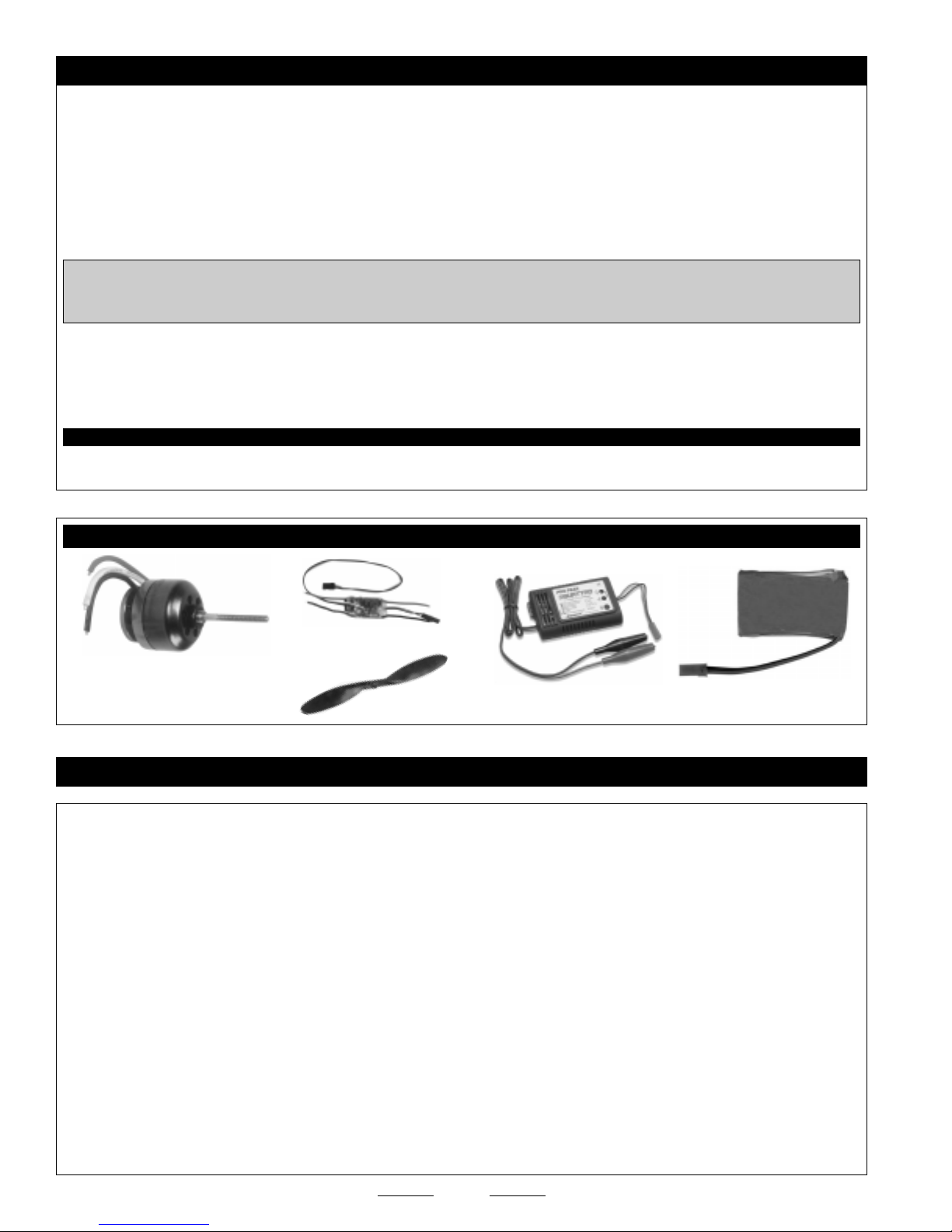
RECOMMENDED ITEMS FOR BRUSHLESS POWER SYSTEM
KMS 18A
Brushless ESC
KMS 2401-9
Brushless Motor
10x3.8 - 10x4.7
Propeller
Quattro LiPO
Battery Charger
WattAge 2-3 Cell 1250mAH
LiPO Battery
LITHIUM POLYMER BATTERY WARNINGS - PLEASE READ
●
LiPO batteries may explode or catch fire. Serious injury can result from misuse.
●
All instructions, warnings and cautions must be followed at all times. Failure to do so can lead to serious injury or fire.
●
Do NOT overcharge. Maximum voltage for each pack must be followed.
●
Do NOT over-discharge. NEVER discharge below minimum volts.
●
Do NOT discharge at a rate greater than the maximum continuous discharge.
●
Do NOT use or charge if the battery is hot.
●
ONLY use a charger made for Lithium Polymer batteries.
●
Do NOT charge at a rate higher than 1C. Example: if the battery’s rating is 340mAH, then the charger’s charge rate must be set at 340mAH or less.
●
Do NOT leave in direct sunlight or in a hot car or storage area.
●
Do NOT get wet or expose to moisture.
●
Do NOT short-circuit the battery.
●
ONLY discharge and charge the battery outdoors or in a fire-safe container.
●
Do NOT charge with reverse polarity.
●
Do NOT leave the battery connected when not in use.
●
Do NOT operate or charge unattended.
●
Do NOT solder to the battery directly and do not get the battery hot in any way.
●
Always let the battery cool and "rest" between uses and charging.
●
Do NOT charge inside your car or inside your house.
●
Inspect the battery before each use for swelling or other malformation. If the cell has ballooned, it MUST be discarded.
●
Set the charger to 1C (charge at 1/2C or less for the first 5 cycles).
●
Check polarity and then connect battery to charger.
●
In use, do not over-discharge or exceed maximum discharge.
●
When handling the battery, remember not to poke, bend or damage the cell. The cell outer casing is soft and can be damaged.
●
Remember, the cells must never exceed 160 degrees Fahrenheit for any reason.
2
Page 3
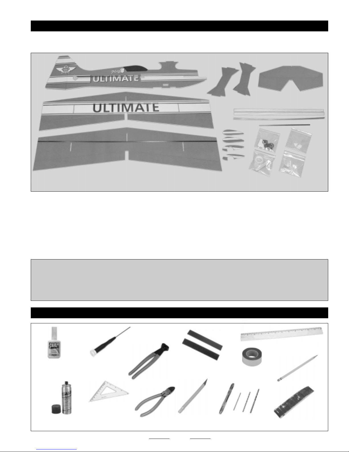
KIT CONTENTS
If you find any parts missing or damaged, please contact us as soon as possible,
using the Customer Service Information on page # 2.
E
A
D
B
N
F
L
G
H
K
C
M
I
J
DEPENDING ON THE KIT YOU HAVE, IT MAY LOOK DIFFERENT FROM THE KIT SHOWN. THE ULTIMATE KIT IS SHOWN.
❑ (A) Fuselage w/Carbon Support Strips - 1
❑ (B) Top Wing and Ailerons w/Carbon Support Strips - 1
❑ (C) Bottom Wing and Ailerons w/Carbon Support Strips - 1
❑ (D) Stabilizer w/Elevator - 1
❑ (E) Rudder - 1
❑ (F) Balsa Triangle Stock - 1
❑ (G) Carbon Landing Gear Struts - 2
❑ (H) Landing Gear Parts Bag - 1
❑ (I) Control Horn and Clevis Bag - 1
❑ (J) Motor Mount and Hinge Tape Bag - 1
❑ (K) Aileron Interlink Connector Bag - 1
❑ (L) Pushrod Wires - 4
❑ (M) Wheel Pant Assemblies - 2
❑ (N) Wing Struts - 2
To save weight and make building time quicker, we suggest using foam-friendly C/A instead of epoxy to assemble the airplane.
If you use C/A, you MUST USE FOAM-FRIENDLY C/A AND FOAM-FRIENDLY C/A "KICKER." If you use C/A and C/A "Kicker"
that is not foam-friendly, the C/A will melt the foam and ruin the airplane.
If you're installing the recommended KMS 2410-9 brushless motor, you will need to make a motor mounting plate out of a piece
of 1/8" plywood. A template and mounting instructions are included on page # 15.
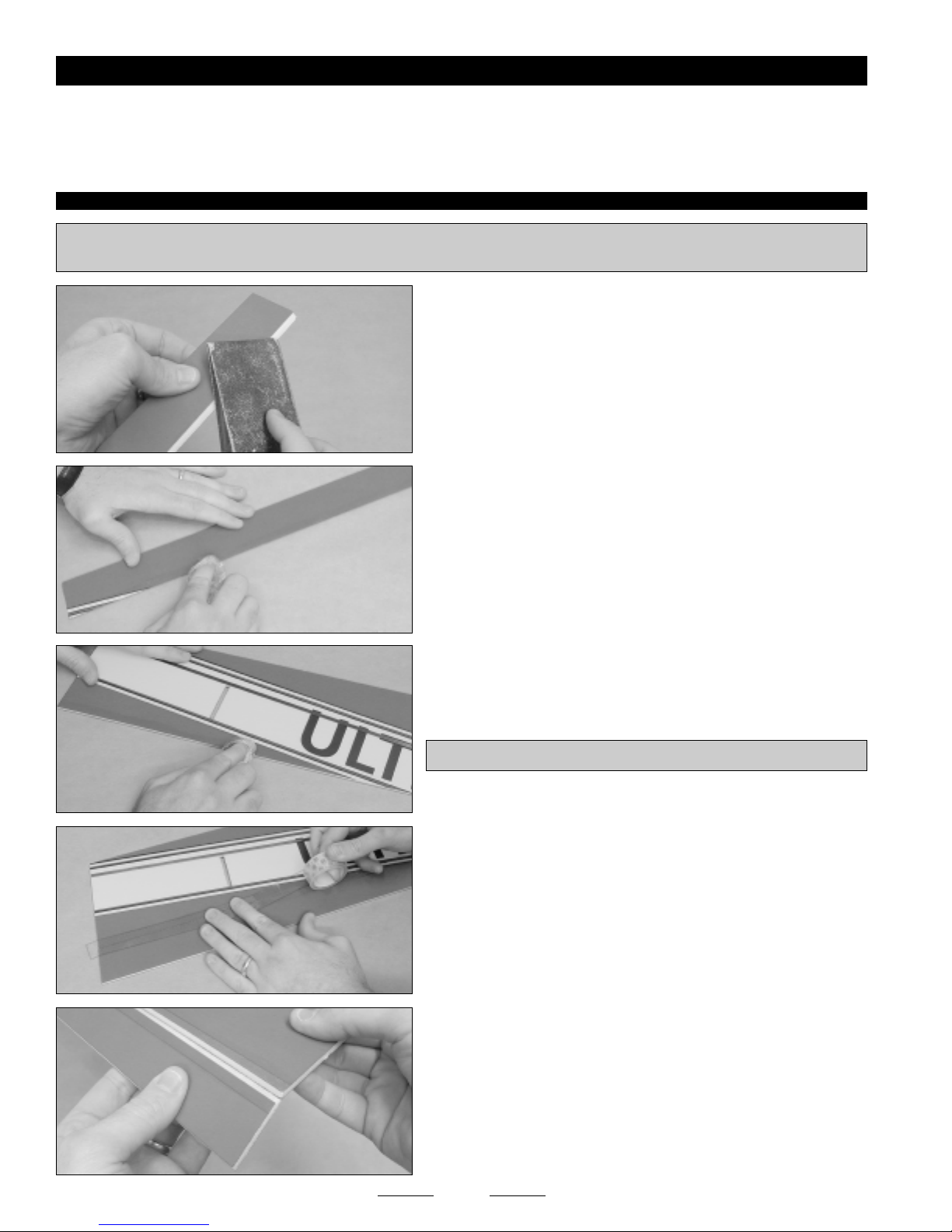
TOOLS AND SUPPLIES REQUIRED
Straight Edge
Ruler
Self-Adhesive
Velcro
Modeling Knife
w/#11 Blade
Double-Sided
Tape
Drill w/Assorted
Drill Bits
Pencil
220 Sandpaper
w/Sanding Block
Pacer Zap-O C/A+
for Foam
Pacer Aerosol Zip-Kicker
Small Phillips Head
Screwdriver
Z-Bend Pliers
Builder's Triangle
or Square
Wire Cutters
3
Page 4
AIRPLANE ASSEMBLY
If you use the Pacer Aerosol Zip-Kicker that is recommended, it is very important that you use it properly to prevent
melting the foam. Always spray a very light "mist" from no less than 12" (305mm) from the surfaces to be glued. After
spraying the surfaces, immediately wipe off any excess with a soft towel. If you spray too much on one area or leave it on
too long, it will melt the foam. All assembly shown is done with foam-friendly C/A and Aerosol Zip-Kicker.
STEP # 1: HINGING THE AILERONS
✦✦
✦IMPORTANT
✦✦
the clear tape stick better to the foam, you should apply a thin layer of foam-friendly C/A to the areas where the clear tape will be applied.
✦✦
✦ To make a strong hinge joint, it's important to apply clear tape to both the top AND bottom of the hinge line. To make
✦✦
❑ Sand a 45º bevel into the bottom leading edge of all four ailerons.
❑ Apply a thin bead of foam-friendly C/A to the top and bottom of the
ailerons (only where the hinge tape will be applied), then spread the
C/A into a thin, even layer, using your finger.
Place your finger in a plastic baggy or wrap plastic wrap around
☞
your finger to prevent getting C/A on your finger.
❑ Apply a thin, even layer of foam-friendly C/A onto the top and bottom
of the wings (only where the hinge tape will be applied).
✦✦
✦IMPORTANT
✦✦
❑ While holding the aileron tight against the wing and level with the top
of the wing, apply a strip of clear tape to the top of the parts to hinge the
aileron into place.
❑ Turn the wing upside down and deflect the aileron up approximately
45º. While holding the aileron up at a 45º angle, apply a strip of clear
tape to the bottom of the hinge line.
❑ Push the clear tape gently into the hinge line, then pivot the aileron up
and down several times to ensure free hinge movement in both directions.
✦✦
✦ Allow the C/A to fully cure before proceeding.
✦✦
❑ Repeat to hinge the remaining three ailerons.
4
Continued On Next Page
☛☛
☛
☛☛
Page 5

STEP # 2: INSTALLING THE BOTTOM WING AND WING STRUTS
❑ Place the bottom wing onto the fuselage. Make sure that the top of
the wing is toward the top of the fuselage.
❑ Use a builder's triangle or square to hold the wing and fuselage
perpendicular to each other, then glue the parts together.
❑ Cut two pieces of balsa triangle stock to a length of 6-1/2" (165mm).
We angled the front and back edges to make a more aerodynamic
☞
shape and for better appearance. This is optional.
❑ Cut a notch on one side of each piece of triangle stock to clear the
carbon strip on the wing.
❑ Glue one piece of triangle stock to each side of the wing and fuselage
to strengthen the joint.
❑ Glue the two wing struts to the top of the wing. Use a builder's
triangle or square to make sure that the wing struts are perpendicular to
the wing.
✦✦
✦IMPORTANT
✦✦
should both be angled forward when viewed from the side.
5
✦✦
✦ Note the direction the wing struts are mounted. They
✦✦
Continued On Next Page
☛☛
☛
☛☛
Page 6

STEP # 3: INSTALLING THE TOP WING
❑ Glue one piece of triangle stock to the inside of each wing strut to
strengthen the joint.
❑ Glue the top wing to the top of the fuselage and wing struts.
❑ Cut and glue pieces of triangle stock to the top wing to strengthen
the glue joints. Glue one piece of triangle stock to the inside of each
wing strut and one piece to each side of the center wing mount.
STEP # 4: INSTALLING THE STABILIZER, ELEVATOR AND RUDDER
❑ Sand a 45º bevel into the bottom leading edge of the elevator.
✦✦
✦IMPORTANT
✦✦
installing the stabilizer. If you don't, it will be impossible to install the elevator after the stabilizer is glued in place.
✦✦
✦ You MUST sand the hinge bevel into the leading edge, then slide the elevator through the fuselage BEFORE
✦✦
❑ Slide the elevator into the fuselage first, then slide the stabilizer into
the fuselage. Make sure that the top of the stabilizer and the top of the
elevator are toward the top of the fuselage.
❑ Align the notches in the front and back of the stabilizer with the
fuselage.
✦✦
✦IMPORTANT
✦✦
of the design, you can simply slide the stabilizer into the fuselage, then hinge the elevator after gluing it into place.
✦✦
✦ If you're building the Pitts, you don't need to sand the bevel in the leading edge of the elevator now. Because
✦✦
6
Continued On Next Page
☛☛
☛
☛☛
Page 7

❑ Use a builder's triangle or square to hold the stabilizer and fuselage
perpendicular to each other, then glue the stabilizer to the fuselage.
❑ Glue one piece of balsa triangle stock to each side of the bottom of
the stabilizer and fuselage joint.
❑ Hinge the elevator to the stabilizer, using the same techniques that
you used to hinge the ailerons to the wing.
✦✦
✦IMPORTANT
✦✦
C/A to the foam, so that the clear tape will stick better.
❑ Sand a 45º bevel into the right side leading edge of the rudder.
❑ Hinge the rudder to the fuselage, using the same techniques that
you used to hinge the elevator to the stabilizer.
✦✦
✦IMPORTANT
✦✦
C/A to the foam, so that the clear tape will stick better.
✦✦
✦ Don't forget to apply a thin layer of foam-friendly
✦✦
✦✦
✦ Don't forget to apply a thin layer of foam-friendly
✦✦
STEP # 5: INSTALLING THE LANDING GEAR STRUTS
❑ Glue one landing gear support plate to each side of the fuselage.
✦✦
✦IMPORTANT
✦✦
positioned as shown. For the Pitts, the front of the support plate
should be even with the angle cut in the bottom of the fuselage.
7
✦✦
✦ For the Ultimate, the support plate should be
✦✦
Continued On Next Page
☛☛
☛
☛☛
Page 8

❑ Drill a 45º angled hole up through the center of one support plate,
through the fuselage and through the other support plate.
❑ Drill a 45º angled hole up through the center of the other side of the
support plate. Position this hole slightly in front of the other hole, so that
the holes don't interfere with each other.
❑ Cut the two carbon struts to a length of 6-1/2" (165mm).
❑ Glue one angled bracket onto one end of one carbon strut.
✦✦
✦IMPORTANT
✦✦
should be away from the end of the carbon strut.
❑ Slide the carbon strut down through one of the holes in the support
plate and push the mounting bracket against the support plate.
❑ Slide a second mounting bracket over the carbon strut (from the
bottom) and push the bracket up against the support plate.
❑ Align the carbon strut so that it's straight (when viewed from the
side), then glue the two mounting brackets and the carbon strut into place.
✦✦
✦ Note the position of the bracket. The angled sides
✦✦
8
Continued On Next Page
☛☛
☛
☛☛
Page 9

❑ Install the second carbon strut and mounting brackets.
STEP # 6: INSTALLING THE WHEELS AND WHEEL PANTS
✦✦
✦IMPORTANT
✦✦
that the ends of both struts line up with each other.
❑ Slide one carbon axle into the axle mounting bracket.
❑ Slide one wheel (flat side first) onto one wheel pant mounting bracket.
✦✦
✦ When you align the second carbon strut, make sure
✦✦
❑ Firmly push the carbon axle into the wheel pant mounting bracket to
secure the assembly together.
Check that the wheel spins freely.
☞
❑ Repeat the previous procedures to make a second wheel and axle
assembly.
❑ Glue the inner wheel pant section to the outer wheel pant section.
✦✦
✦IMPORTANT
✦✦
❑ Glue the wheel pant mounting bracket to the inside of one wheel
pant. The base of the bracket (the straight side) should be even with
the bottom of the wheel pant and the wheel should be centered from
side to side.
✦✦
✦ Make two wheel pants - one right and one left.
✦✦
9
Continued On Next Page
☛☛
☛
☛☛
Page 10

✦✦
✦IMPORTANT
✦✦
are the same length. If one is longer than the other, cut the longer one shorter so that they're both the same length.
❑ Install the second wheel and wheel pant assembly. Before gluing the axle mounting bracket into place, make sure that the wheel
pant points straight ahead and that the wheel pant is even with the other wheel pant when viewed from the side.
STEP # 7: INSTALLING THE ELEVATOR AND RUDDER SERVOS
✦✦
✦ Before gluing the axle mounting bracket to the carbon struts, measure and make sure that both carbon struts
✦✦
❑ Slide the axle mounting bracket onto the end of the carbon strut,
then line up the wheel pant. It should point straight ahead and should
also be level when viewed from the side.
❑ Glue the axle mounting bracket to the carbon strut.
❑ Install the elevator and rudder servos into the fuselage. Use a couple
of drops of foam-friendly C/A to secure them into place. Notice that the
elevator servo is mounted on the left side of the fuselage and the rudder
servo is mounted on the right side of the fuselage.
STEP # 8: INSTALLING THE ELEVATOR PUSHROD
✦✦
✦IMPORTANT
✦✦
of the airplane.
❑ Make a Z-Bend in one end of one pushrod wire.
❑ So that you can adjust the length of the pushrod after it's installed,
make a V-Shaped bend 2" (51mm) behind the Z-Bend.
❑ Install one control horn onto the bottom of the left side of the elevator,
5/8" (16mm) out from the side of the fuselage, using the wood screws
provided.
✦✦
✦ The servo output shafts should be toward the front
✦✦
❑ Attach the Z-Bend into the outermost hole in the servo arm.
10
Continued On Next Page
☛☛
☛
☛☛
Page 11

❑ Center the elevator servo, then attach the servo arm onto the servo,
making sure that it's centered and pointing down.
✦✦
✦IMPORTANT
✦✦
to secure the servo arm to the servo.
❑ Slide one pushrod support (extra control horn) over the end of the
pushrod wire.
✦✦
✦IMPORTANT
✦✦
fuselage yet. Glue it into place AFTER installing the clevis.
❑ Check that the servo arm is still centered, then center the elevator.
❑ Cut the pushrod wire to length and slide one clevis over the end of
the pushrod wire.
❑ Snap the clevis into the outermost hole in the control horn, then glue
the clevis to the pushrod wire.
✦✦
✦ Remember to install the servo arm retaining screw,
✦✦
✦✦
✦ Don't glue the pushrod support to the side of the
✦✦
STEP # 9: INSTALLING THE RUDDER PUSHROD
❑ Center the pushrod support, then glue it to the fuselage side.
❑ Install one control horn onto the right side of the rudder, 1-7/8"
(47.5mm) above the bottom of the rudder.
❑ Make a Z-Bend and V-Shaped bend in one end of one pushrod wire.
❑ Install the Z-Bend into the servo arm, then attach the servo arm onto
the servo, making sure that it's centered and pointing down.
11
Continued On Next Page
☛☛
☛
☛☛
Page 12

❑ Slide one pushrod support (extra control horn) over the end of the
pushrod wire.
❑ Check that the servo arm is still centered, then center the rudder.
❑ Cut the pushrod wire to length, snap the clevis into the outermost
hole in the control horn, then glue the clevis to the pushrod wire.
❑ Center the pushrod support, then glue it to the fuselage side.
STEP # 10: INSTALLING THE AILERON SERVO AND PUSHRODS
❑ Center the aileron servo, then attach the servo arm onto the servo,
making sure that it's centered.
❑ Install the aileron servo to the left side of the fuselage, using a couple
of drops of foam-friendly C/A.
✦✦
✦IMPORTANT
✦✦
of the airplane and the servo arm should be centered in the cutout in
the fuselage.
❑ Install one control horn onto the top of both bottom wing ailerons,
5/8" (16mm) out from the sides of the fuselage.
✦✦
✦ The servo output shaft should be toward the front
✦✦
❑ Make a Z-Bend in one end of two pushrod wires.
❑ Make a V-Shaped bend 1" (25mm) behind the Z-Bends.
12
Continued On Next Page
☛☛
☛
☛☛
Page 13

❑ Check that the servo arm is still centered, then center both ailerons.
❑ Install the Z-Bends into the outermost holes in the servo arm, then
cut the pushrod wires to length, snap the clevises into the outermost
holes in the control horns, and glue the clevises to the pushrod wires.
STEP # 11: INSTALLING THE AILERON INTERLINK PUSHRODS
❑ Glue one plastic pushrod mount to the bottom of each aileron.
Position the pushrod mounts in the center of the ailerons.
❑ Make a Z-Bend in one end of one pushrod wire.
❑ Secure the Z-Bend into the outermost hole in the upper pushrod
mount.
❑ Center the top and bottom ailerons, cut the pushrod wire to length,
snap a clevis into the outermost hole in the lower pushrod mount, and
glue the clevis to the pushrod wire.
❑ Repeat the previous procedures to install the second aileron interlink pushrod.
STEP # 12: INSTALLING YOUR RECEIVER AND ESC
❑ Install your receiver and ESC onto the left side of the fuselage, using
velcro or double-sided tape.
✦✦
✦IMPORTANT
✦✦
receiver. You will also need to make a small hole in front of the ESC for the battery plug. The battery will be mounted on the right
side of the fuselage.
✦✦
✦ You will need to make a small hole through the fuselage so that the rudder servo lead can be plugged into the
✦✦
❑ Extend the antenna along the bottom of the fuselage and hold it in
place using small pieces of clear tape.
13
Continued On Next Page
☛☛
☛
☛☛
Page 14

STEP # 13: INSTALLING YOUR MOTOR, BATTERY AND PROPELLER
❑ Glue the motor mount into the gear box mount.
❑ Temporarily slide the motor mount onto the front of the fuselage.
✦✦
✦IMPORTANT
✦✦
❑ Install your propeller onto your motor. Temporarily set your battery
on top of the wing, over the C/G, then check the balance of the airplane
(refer to page # 15). If the airplane is nose heavy, remove the motor
assembly and cut the motor mount shorter, so that the motor is mounted
further back. Repeat this procedure until the airplane balances. If the
airplane is tail heavy, don't cut the motor mount shorter. Leave it the
standard length. You'll simply need to mount the battery farther forward
when you install it later.
❑ Center the motor mount and double-check that the motor is straight.
When satisfied with the alignment, glue the motor mount to the fuselage.
✦✦
✦ Don't glue the motor mount to the fuselage yet.
✦✦
❑ Mount your battery to the right side of the fuselage, using a piece of
velcro. Position the battery at the location necessary to balance the
airplane.
❑ Install your propeller onto your motor and finish wiring your motor to
your ESC.
14
Continued On Next Page
☛☛
☛
☛☛
Page 15

INSTALLING THE KMS 2410-9 BRUSHLESS MOTOR
❑ Use the template to cut out the motor mount from a piece of 1/8"
plywood (not included).
❑ Slide the motor mounting stick into the fuselage. You may need to
cut the stick shorter so that it's flush with the front of the fuselage.
❑ Center the motor mounting stick and double-check that it is straight.
When satisfied with the alignment, glue the motor mounting stick to the
fuselage.
❑ Mount the motor to the motor mounting plate, using the hardware
provided with the motor.
❑ Glue the motor mounting plate to the motor mounting stick and the
front of the fuselage.
BALANCING AND CONTROL THROWS CAN
BE FOUND ON THE BACK PAGE
REPLACEMENT PARTS
We stock replacement parts for your Phase 3 airplanes. Listed below are the replacement parts that are available along with their
respective part numbers for easy ordering convenience. We suggest ordering directly from your local dealer.
If your dealer does not stock Phase3 products, you can order replacement parts
directly from us, using the Customer Service Information on page # 2.
Ultimate - Complete ....................................................... 107012
Pitts - Complete ............................................................. 107011
Brushed ESC for 2 Cell LiPO ........................................ 109109
Motor and Gear Box ...................................................... 109111
Propeller ......................................................................... 109112
Gear Box Only ............................................................... 109113
Main Gear and Shaft Only for Gear Box ....................... 109114
Landing Gear Assembly ................................................ 109115
Control Horn and Clevis Bag ......................................... 109116
Carbon Support Strips (4).............................................. 109117
2 Cell 1250mAH LiPO Battery ....................................... 128755
Quattro LiPO Charger .................................................... 158370
15
Page 16

BALANCE POINT AND CONTROL THROWS
BALANCE POINT AND CONTROL THROWS FOR ULTIMATE
Balance Point:
2-3/4" - 3-3/4" (70mm - 92mm) back from the leading edge of the TOP wing, at the fuselage sides.
We suggest starting with the balance point at 2-3/4" (70mm), then moving it back as you become more proficient with the
airplane. Moving the balance point back will make the airplane more aerobatic, but less stable.
DO NOT fly the airplane without first balancing it. The airplane should sit level or slightly nose down when you lift it up with your
fingers at the balance point. It might be necessary to move the battery forward or backward to balance the airplane.
Control Throws:
TEST-FLYING
Ailerons: 15º Up & Down
Elevator: 15º Up & Down
Rudder: 15º Right & Left
Control throws are measured from the
widest point of the control surfaces
Ailerons: 40º or More Up & Down
Elevator: 40º or More Up & Down
Rudder: 40º or More Right & Left
3D-FLYING
BALANCE POINT AND CONTROL THROWS FOR PITTS
Balance Point:
3-1/4" - 4-1/2" (82mm - 114mm) back from the leading edge of the TOP wing, at the fuselage sides.
We suggest starting with the balance point at 3-1/4" (82mm), then moving it back as you become more proficient with the
airplane. Moving the balance point back will make the airplane more aerobatic, but less stable.
DO NOT fly the airplane without first balancing it. The airplane should sit level or slightly nose down when you lift it up with your
fingers at the balance point. It might be necessary to move the battery forward or backward to balance the airplane.
Control Throws:
TEST-FLYING
Ailerons: 15º Up & Down
Elevator: 15º Up & Down
Rudder: 15º Right & Left
Control throws are measured from the
widest point of the control surfaces
Ailerons: 40º or More Up & Down
Elevator: 40º or More Up & Down
Rudder: 40º or More Right & Left
3D-FLYING
Phase3 guarantees this kit to be free from defects in both material and workmanship at the date of purchase. This does not cover any
component parts damaged by use, misuse or modification. In no case shall Phase3's liability exceed the original cost of the
purchased kit.
In that Phase3 has no control over the final assembly or material used for final assembly, no liability shall be assumed for any damage
resulting from the use by the user of the final user-assembled product. By the act of using the final user-assembled product, the user accepts
all resulting liability.
OUR GUARANTEE
16
 Loading...