

Global Hobby Global SST 09 ARF Instructions Manual
Electric Conversion Instructions Included
in This Manual - See Page 26 for Details!
INSTRUCTIONS FOR FINAL ASSEMBLY
The Global SST 09 ARF is in no way a primary trainer. If you have not flown an R/C airplane before, please
return this kit to the place of purchase before going any further. The SST 09 is designed for those pilots who are
already skilled at flying a basic trainer or sport airplane. Even though the SST 09 is small, it can be a very high
performance aircraft, depending upon which engine and radio accessories you use. These options are discussed
in further detail to help you make the right choice for your desired style of flying.
T o make your modeling experience totally enjoyable, we recommend that you get experienced, knowledgable
help with assembly and during your first flights. Your local hobby shop has information about flying clubs in
your area whose membership includes qualified instructors. W e also recommend that you contact the AMA at
the address below. They will be able to help you locate a flying field in your area also.
Academy of Model Aeronautics
5151 East Memorial Drive
Muncie, IN. 47302-9252
(800) 435-9262
www.modelaircraft.org
The SST 09 ARF is distributed exclusively by Global Hobby Distributors 18480 Bandilier Circle Fountain Valley, CA 92728
All contents copyright © 2000, Global Hobby Distributors Version V1.2 6/00
1

TABLE OF CONTENTS
Introduction .....................................................3
Kit Contents.....................................................4
Metric Conversion Chart .................................5
Full Size Hardware Drawings .........................6
Additional Items Required ..............................7
Tools and Supplies Needed..............................7
Field Support Equipment Needed ...................7
Wing Mounting................................................8
Installing the Hardwood Dowels ..............8
Aligning the Wing.....................................8
Mounting the Wing...................................8
Horizontal Stabilizer Installation.....................9
Aligning the Horizontal Stabilizer............9
Mounting the Horizontal Stabilizer ........10
Hinging the Elevator...............................10
Vertical Stabilizer Installation ....................... 11
Mounting the Vertical Stabilizer.............11
Tail Skid Installation......................................11
Installing the Tail Skid ............................11
Landing Gear Installation ..............................12
Installing the Landing Gear Wires..........12
Installing the Wheels ..............................12
Engine Mounting ...........................................13
Installing the Exhaust Extension ............13
Aligning the Engine ................................13
Mounting the Engine ..............................13
Installing the Spinner ..............................13
Installing the Throttle Pushrod ...............14
Fuel Tank .......................................................14
Stopper Assembly ...................................14
Installing the Stopper ..............................14
Fuel Tank Installation .............................15
Servo Installation...........................................15
Installing the Servo Rails........................15
Installing the Fuselage Servos ................15
Installing the Aileron Servo Plates .........16
Installing the Aileron Servo....................16
Throttle Servo ................................................17
Installing the Servo Connector ...............17
Elevator Pushrod ...........................................17
Installing the Control Horn .....................17
Installing the Pushrod .............................18
Adjusting the Elevator Pushrod ..............19
Aileron Linkage.............................................19
Hinging the Ailerons...............................19
Installing the Aileron Linkage ................20
Adjusting the Aileron Linkage ...............21
Final Assembly ..............................................21
Installing the Fuel Lines .........................21
Installing the Switch ...............................21
Installing the Battery and Receiver.........21
Balancing .......................................................22
Control Throws..............................................23
Preflight Check ..............................................23
Flying the SST 09 ..........................................23
Glossary of Terms..........................................24
Notes..............................................................25
SST 09 Electric Conversion ..........................26
Trim Chart .....................................................30
Product Evaluation Sheet ..............................31
Global guarantees this kit to be free from defects in both material and workmanship, at the date of purchase.
This does not cover any components parts damaged by use, misuse or modification. In no case shall
Global's liability exceed the original cost of the purchased kit.
In that Global has no control over the final assembly or material used for final assembly , no liability shall be
assumed for any damage resulting from the use by the user of the final user-assembled product. By the act
of using the final user-assembled product, the user accepts all resulting liability .
2

INTRODUCTION
Thank you for choosing the Global SST 09 ARF for your next airplane. The SST 09 ARF is
designed to be powered with either an .09 size engine, like the AP Engines Hornet, or a .15 size
engine, like the AP Engines .15 Yellowjacket. Performance is excellent using either engine. The
smaller engine will allow the SST to be flown slower and in a much smaller space. Using the larger
engine, the SST turns into a high performance sport plane. The airplane uses three channel controlelevator, ailerons and throttle. Standard servos can be used in the fuselage, and a mini servo in the
wing. To make the airplane even lighter, micro servos can be used on all controls.
The SST 09 ARF is completely built up out of balsa and light ply. This really helps keep the weight
down, owing to its excellent performance. The airframe is then covered with lightweight polyester
covering material in an attractive color scheme. Included in the box is a full compliment of hardware,
including prebent main landing gear wires, prebent tail skid, lightweight wheels, wheel collars, fuel
tank, pushrods, and all of the nuts and bolts.
We hope you enjoy final assembly and flying of your new SST 09 ARF as much as we have
enjoyed designing and building it for you. If you have any questions or comments, please feel free
to contact us and let us know. W e have also included a product survey in the back of this instruction
manual. Please take the time to fill it out and send it to us. We always enjoy hearing any comments
or suggestions you may have.
This instruction manual is designed to guide you through the entire assembly process of your new SST 09
ARF in the least amount of time possible. Along the way you'll learn how to properly assemble your new
airplane and also learn many tips that will help you in the future. W e have listed some of our recommendations
below . Please read through them before going any further.
ü Please read through each step before starting assembly. You should find the layout very complete
and simple. Our goal is to guide you through assembly without any of the headaches and hassles you
might expect.
ü When you are ready to glue any parts together, test fit them first without using glue. This will ensure
you have the correct parts and that they fit together properly.
ü There are check boxes next to each step. After you complete a step, check off the box. This will help
you keep from losing your place.
ü If you come across this symbol , it means that this is an important point or an assembly hint.
ü Cover your work table with brown paper or a soft cloth, both to protect the table and to protect the
individual parts.
ü Keep a couple of small bowls or jars handy to put the small parts in after you open the accessory bags.
ü We have included a glossary of terms beginning on page # 24. Check it out if you come across a term
that is unfamiliar to you.
ü We're all excited to get a new airplane in the air, but take your time. This will ensure you build a
straight, strong and great flying airplane.
If you should find a part missing or damaged, or have any questions about assembly , please contact us at the
address below:
Global Hobby Distributors Customer Care
18480 Bandilier Circle
Fountain Valley, CA 92728
Phone: (714) 963-0329
Fax: (714) 964-6236
E-mail: service@globalhobby.com
3
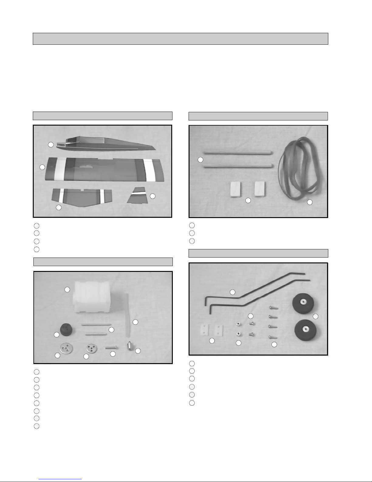
KIT CONTENTS
W e have organized the parts as they come out of the box for easier identification during assembly. Each photo
below represents the parts that are required in a main section of the assembly process. Before you begin
assembly , group the parts like we show . This will ensure you have all of the parts before you begin assembly . It
will also help you become familiar with each part. The corresponding part number is listed first, then the
quantity of that particular part, along with a short description of the part. As you proceed through assembly, you
will notice the same part number listed next to a particular part necessary for that step. If you have any
questions as to what that part might be, refer back to this section.
AIRFRAME ASSEMBLIES
1
2
3
1
q {1} Fuselage w/Pushrod Housing
2
q {1} Wing Assembly w/Ailerons & Hinges
3
q {1} Horizontal Stabilizer w/Elevator & Hinges
4
q {1} V ertical Stabilizer
FUEL TANK ASSEMBLY
5
WING ASSEMBLY
14
4
13
q {2} 3mm x 15mm x 25mm Plywood Plates
14
q {2} 7mm x 110mm Hardwood Dowels
15
q {4} Rubber Bands
13
15
MAIN GEAR ASSEMBLY
16
11
10
5
q {1} 115cc Fuel Tank
6
q {2} Aluminum Tubes
7
q {1} Weighted Fuel Pickup
8
q {1} Silicon Fuel Tubing
9
q {1} 17mm Diameter Rear Plate
10
q {1} 20mm Diameter Front Plate
11
q {1} Rubber Stopper
12
q {1} 3mm x 18mm Machine Screw
9
6
12
8
20
7
16
q {2} Prebent Main Gear Wires
17
q {2} 35mm Diameter Wheels
18
q {2} 3mm Wheel Collars
19
q {2} 3mm x 5mm Machine Screws
20
q {2} Nylon Landing Gear Straps
21
q {4} 3mm x 12mm Wood Screws
19
18
21
17
4
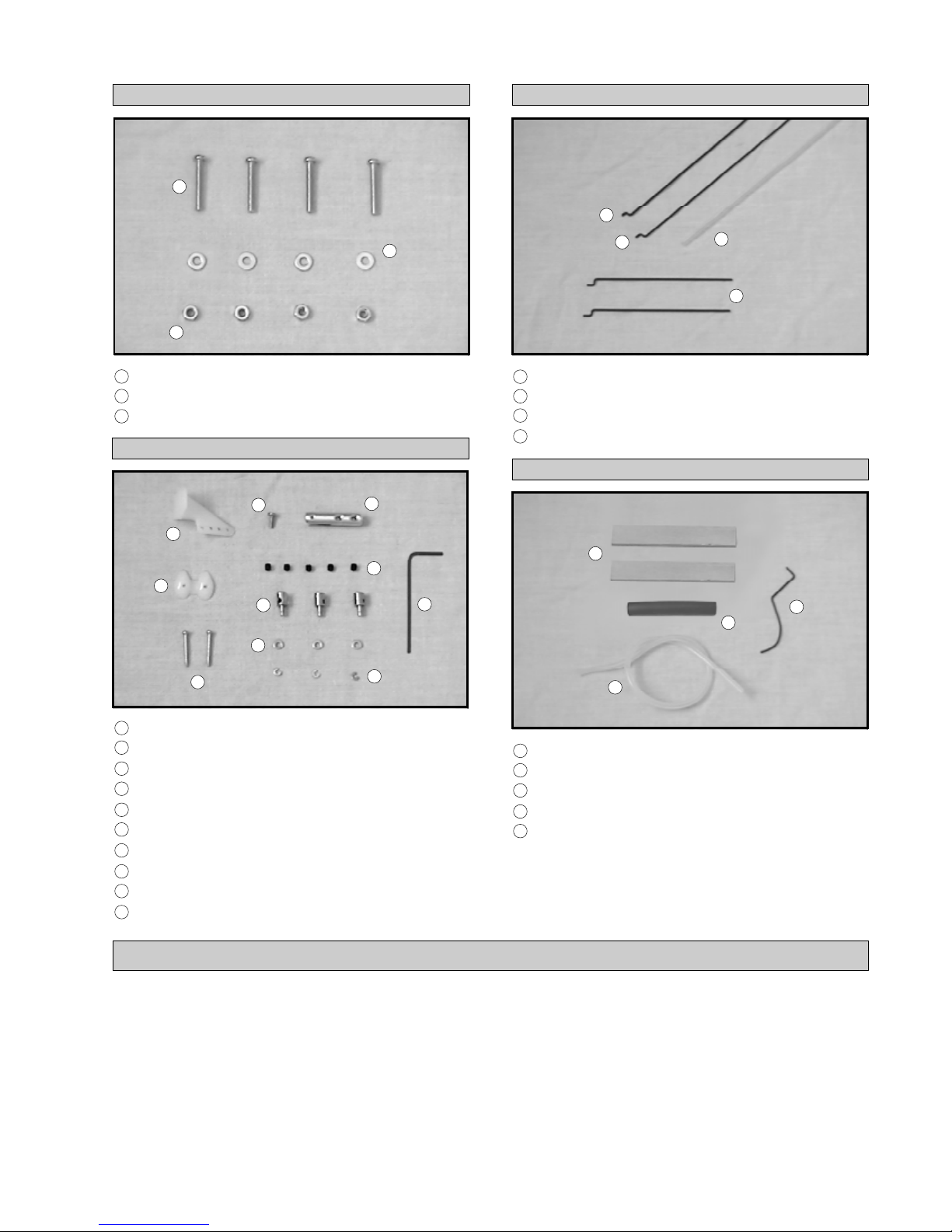
ENGINE MOUNTING
22
24
PUSHROD ASSEMBLIES
35
23
36
38
37
22
q {4} 3mm x 20mm Machine Screws
23
q {4} 3mm Flat Washers
24
q {4} 3mm Hex Nuts
PUSHROD CONNECTOR ASSEMBLIES
30
25
26
28
31
27
25
q {1} Nylon Control Horn
26
q {1} Nylon Control Horn Backplate
27
q {2} 2mm x 15mm Wood Screws
28
q {3} Adjustable Servo Connectors
29
q {1} Adjustable Clevis
30
q {1} 2mm x 6mm Machine Screw
31
q {3} 2mm Flat Washers
32
q {3} 2mm C-Clips
33
q {5} 2mm Set Screws
34
q {1} Allen Wrench
29
33
32
35
q {1} 2mm x 545mm Wire w/Z-Bend
36
q {1} 1.5mm x 330mm Wire w/Z-Bend
37
q {2} 1.5mm x 100mm Wires w/Z-Bends
38
q {1} 4mm x 200mm Nylon Pushrod Tube
MISCELLANEOUS
39
34
42
41
39
q {2} 3mm x 10mm x 65mm Plywood Servo Rails
40
q {1} Prebent Tail Skid
41
q {1} Silicon Fuel Tubing
42
q {1} Exhaust Extension Tube
43
q {1} Spinner Assembly (not pictured)
40
To convert inches into millimeters: Inches x 25.4 = MM
1/64” = .4mm
1/32” = .8mm
1/16” = 1.6mm
3/32” = 2.4mm
1/8” = 3.2mm
5/32” = 4.0mm
3/16” = 4.8mm
1/4” = 6.4mm
3/8” = 9.5mm
1/2” = 12.7mm
5/8” = 15.9mm
3/4” = 19.0mm
METRIC CONVERSION CHART
1” = 25.4mm
2” = 50.8mm
3” = 76.2mm
6” = 152.4mm
12” = 304.8mm
18” = 457.2mm
5
21” = 533.4mm
24” = 609.6mm
30” = 762.0mm
36” = 914.4mm
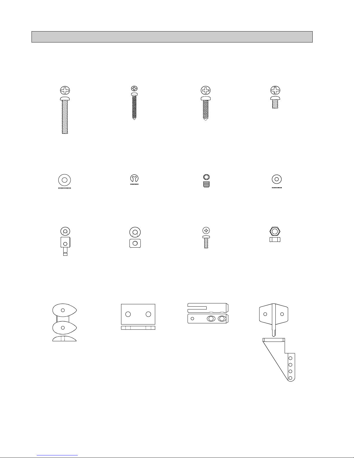
FULL SIZE HARDWARE DRAWINGS
Listed below are full size drawings of the small hardware items included with the SST 09 ARF. Use these
drawings to familiarize yourself with each of these parts. Please refer back to this page to locate the proper
hardware items when they are needed for a particular assembly step. These drawings are especially helpful
when trying to identify the different size screws or nuts used in a particular step.
3mm x 20mm
Machine Screw
3mm Flat
Washer
Adjustable Servo
Connector
2mm x 15mm
Wood Screw
2mm
C-Clip
3mm Wheel
Collar
3mm x 12mm
Wood Screw
2mm Set
Screw
2mm x 6mm
Machine Screw
3mm x 5mm
Machine Screw
2mm Flat
Washer
3mm Hex
Nut
Nylon Control
Nylon Landing
Horn Backplate
Gear Strap
Adjustable
Clevis
Nylon
Control Horn
6
ADDITIONAL ITEMS REQUIRED
q {1} Hitec 4 or More Channel Radio w/2 Stnd. Servos
q {1} Cirrus CS-26 Sub Micro Servo # 444238
q {1}Cirrus 12” Servo Extension # 444713
q {1}Dubro Foam Rubber # 868638
q {1}Dubro Hook & Loop Material # 568906
FOR 2 CYCLE .09 ENGINE
q {1}AP .09 R/C Hornet # 211300
q {1}Master Airscrew 7 x 4 Propeller # 244350
q {1} Thunderbolt R/C Short Glow Plug # 115535
q {1}AP NFX 15% Nitro Fuel # 211115
FOR 2 CYCLE .15 ENGINE
q {1}AP .15 R/C Y ellowjacket # 211315
q {1}Master Airscrew 8 x 4 Propeller # 244459
q {1} Thunderbolt R/C Short Glow Plug # 115535
q {1}AP NFX 15% Nitro Fuel # 211115
q {3}Cirrus CS-20 Micro Servos # 444232
q {1}Cirrus 270Mah Battery Pack # 444603
q {1} Cirrus On-Board Battery Indicator # 444762
q {1} Prather Prop Balancer # 520429
q {1}Dubro In-Line Fuel Filter # 568900
IMPORTANT The part numbers for the Cirrus
servos, On-Board Battery Indicator and battery
pack are for Hitec and JR radio systems. These
items are also available with different connectors
for use with Futaba and Airtronics radio systems.
OPTIONAL ITEMS
Please Read Below -
Important Infor mation
FOR YOUR INFORMATION The SST 09 can be set up a couple of different ways to suit your
particular flying needs. Set up stock using an .09 displacement engine and standard servos, the SST 09 is a
very docile flyer that is not too fast. Set up with a .15 displacement engine and micro servos and battery
pack will make the SST 09 a very fast and aerobatic flyer. Remember, the overall finished weight of the
airplane will be almost 4oz. lighter by using micro servos and a 270Mah battery pack. The lighter the
airplane is, the better it will fly. The SST 09 flies very well using the .09 and standard servos. It's an
extreme flyer using a .15 and micro servos. On page # 26 we have even included a section telling you how
to convert your SST 09 into electric! If you do decide to convert the SST 09 to electric, please read that
section before starting assembly of the airplane. Again, the electric conversion section can be found on
page # 26 along with a complete list of the extra items you'll need.
q Kwik Bond Thin C/A # 887500
q Kwik Bond Thick C/A # 887510
q Kwik Bond 30 Minute Epoxy # 887565
q Dubro T-Pins # 567685
q Electric or Hand Drill
q Assorted Drill Bits
q Excel Modeling Knife # 692808
q Machine Oil or Vaseline
q Phillips Head Screwdriver
q 220 Grit Sandpaper w/Sanding Block
q Ernst Airplane Stand # 223977
q Scissors
TOOLS AND SUPPLIES NEEDED
q W axed Paper
q Pen or Pencil
q Builders Triangle
q 3M Masking Tape # 229685
q Paper Towels
q Rubbing Alcohol
q Wire Cutters
q NHP Epoxy Mixing Sticks # 864204
q NHP Mixing Cups # 864205
q 36” Straight Edge Ruler
q Magnum 1/8” Tubing Bender # 237474
7
WING MOUNTING
PARTS REQUIRED
1
q {1} Fuselage w/Pushrod Housing
2
q {1} Wing Assembly w/Ailerons & Hinges
14
q {2} 7mm x 110mm Hardwood Dowels
15
q {4} Rubber Bands
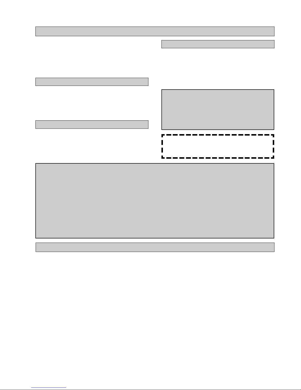
INSTALLING THE HARDWOOD DOWELS
Photo # 2
q 1) Using a modeling knife, carefully remove the
covering from over the four predrilled holes in the
fuselage sides. Two holes are located in front of the
wing saddle, 4-1/8” behind the firewall and 3/8” down
from the top of the fuselage. Two holes are located
in back of the wing saddle, 12-1/2” behind the firewall and 5/16” down from the top of the fuselage.
q 2) Slide one 7mm x 110mm hardwood dowel
through the two predrilled holes in front of the wing
saddle and one dowel through the two predrilled
holes in back of the wing saddle. Center the two
dowels in the fuselage. Both ends of each dowel
should protrude from the fuselage sides equal
amounts. See photo # 1 below.
Photo # 1
These two marks will help you align the wing
when you install it onto the fuselage. Y ou may
wish to make these marks in permanent ink so you
can align the wing correctly each time you install it.
This will ensure the wing is aligned properly every
time you fly the airplane.
q 6) Using a ruler and a pen, locate and mark the
centerline of the wing at both the leading edge and
the trailing edge. See photo # 3 below.
Photo # 3
You may wish to make these marks in perma-
nent ink so you can align the wing correctly
each time you install it.
q 3) With both wing dowels properly positioned,
apply a couple of drops of Kwik Bond Thin C/A to
the joint where each dowel exits the fuselage sides.
Allow the glue to fully cure before proceeding.
The thin C/A will wick into the joint, gluing
the dowels securely in place. Be careful not to
use too much C/A or it may run down the fuselage.
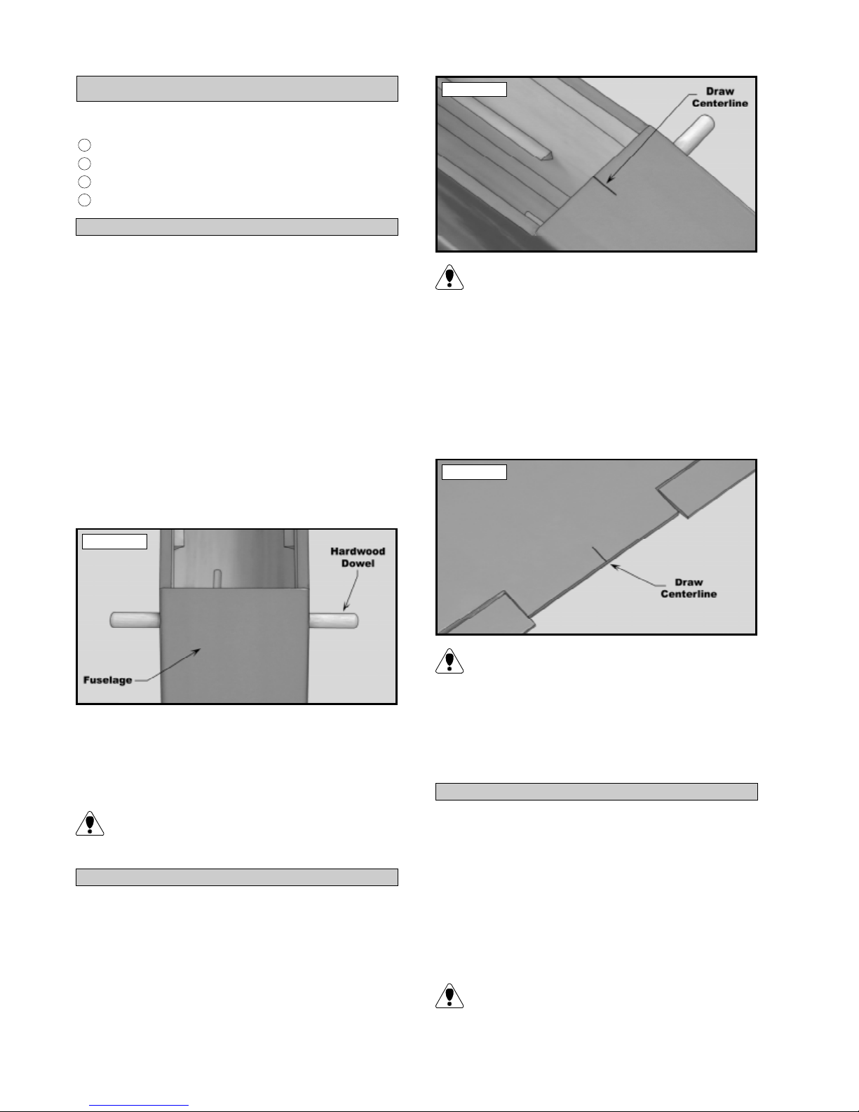
ALIGNING THE WING
q 4) Using a ruler and a pen, locate the centerline
of the fuselage at the front of the wing saddle and
place a mark.
q 5) Using a ruler and a pen, locate the centerline
of the fuselage at the back of the wing saddle and
place a mark. See photo # 2 at top right.
q 7) Place the wing onto the wing saddle. Align
the two centerline marks on the wing with the two
centerline marks on the fuselage.
MOUNTING THE WING
q 8) Temporarily mount the wing to the fuselage
using one rubber band per side. To properly install
the rubber bands, hook one rubber band over one side
of the front wing hold down dowel. Carefully pull it
back over the wing, and under the rear hold down
dowel on the same side, then pull it forward across
the top of the wing and hook it around the front wing
hold down dowel on the same side.
When installing the rubber bands, be careful not
to crush the trailing edge of the wing. Also make
sure that the wing stays centered on the fuselage.
8
HORIZONTAL STABILIZER
INSTALLATION
PARTS REQUIRED
3
q {1} Horizontal Stabilizer w/Elevator & Hinges
q 5) Slide the stabilizer into the mounting slot.
For now, push the leading edge of the stabilizer up
against the front of the slot and carefully align the
two marks at the trailing edge of the stabilizer with
the fuselage sides.
ALIGNING THE HORIZONTAL STABILIZER
q 1) Using a modeling knife, carefully remove
the covering from over the stabilizer mounting slot
in each fuselage side. The front of the slot is 6-3/4”
in front of the back edge of the fuselage and 3/8” up
from the bottom. The slot is about 5” long. See
photo # 4 below.
Photo # 4
q 2) Remove the elevator and hinges from the
horizontal stabilizer and set them aside for now.
q 3) Using a ruler and a pen, locate the centerline
of the horizontal stabilizer, at the trailing edge, and
place a mark. See photo # 5 below.
Photo # 5
q 6) While holding the trailing edge of the stabilizer aligned with the fuselage sides, insert a T-pin
through the bottom of the fuselage and into the stabilizer. This will keep the back of the stabilizer from
moving side-to-side. See photo # 7 below.
Photo # 7
q 7) With the wing still attached to the fuselage
and centered, remove both of the ailerons and hinges.
Set them aside for now.
q 8) Align the stabilizer to the wing. Using a long
ruler, measure from each wing tip to each stabilizer
tip. Both distances should be equal. If they are not,
adjust the stabilizer, making sure the trailing edge
stays centered, until you are satisfied with the alignment. See figure # 1 below.
q 4) Using a ruler and a pen, measure out 3/8”
from each side of the centerline and place a mark.
See photo # 6 below.
Photo # 6
Figure # 1
A=A-1
q 9) When you are satisfied with the alignment,
use several pieces of masking tape to hold the stabilizer firmly in place.
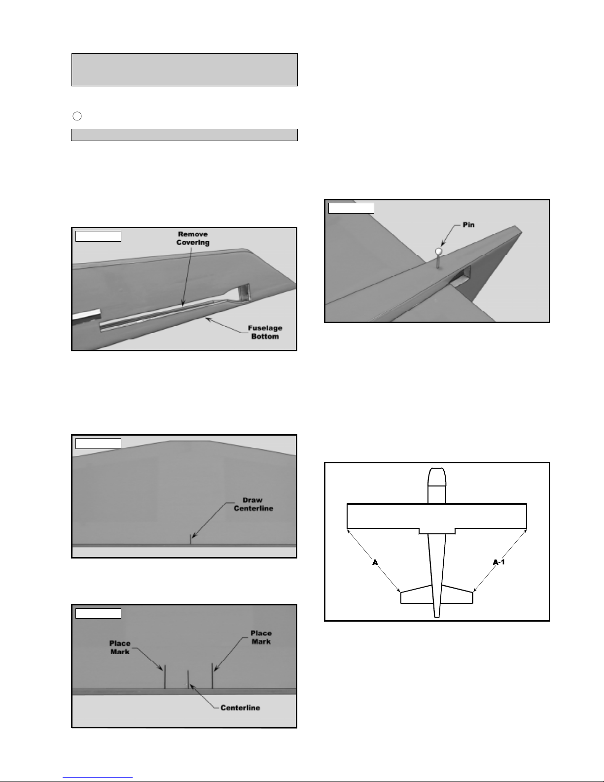
q 10) Now check to ensure that the horizontal stabilizer is level with the wing. When viewed from the
front, the horizontal stabilizer should be level with
the wing. If it is not level, remove the stabilizer and
9
use 220 grit sandpaper, with a sanding block, and sand
down the high side of the stabilizer mounting slot.
Remove small amounts at a time, checking your work
often, until the proper alignment is achieved. See
figure # 2 below.
Figure # 2
B=B-1
MOUNTING THE HORIZONTAL STABILIZER
q 11) With the stabilizer held firmly in place and
properly aligned, use a pen and draw lines onto the
stabilizer, where it and the fuselage sides meet. Do
this on both the right and left sides, on the top and
bottom of the stabilizer.
q 12) Remove the stabilizer from the fuselage.
Using the lines you just drew as a guide, carefully
remove the covering from between them using a
modeling knife. See photo # 8 below.
Photo # 8
Photo # 9
q 14) Carefully slide the elevator through the stabilizer mounting slot, making sure that the hinges are
facing forward and that the colored trim is facing up.
Push the elevator joiner back into the slot as far as
possible and let is set there for now.
q 15) Glue the horizontal stabilizer in place using Kwik Bond 30 Minute Epoxy. Because the
stabilizer has to slide in place through the fuselage,
we suggest you apply a liberal amount of epoxy to
only the gluing surface of the stabilizer. This will
prevent spreading epoxy over the entire length of
one half of the stabilizer when you slide it in place.
After applying the epoxy, slide the stabilizer into
place and realign it. Double check all of your measurements before the epoxy cures. Wipe away any
excess epoxy using paper towels and rubbing alcohol and hold the stabilizer in place using pieces
masking tape.
When cutting through the covering to remove
it, cut with only enough pressure to only cut
through the covering itself. Cutting into the balsa
may weaken the stabilizer.
Please follow the next few steps very closely.
They will lead you through the proper order
for gluing the stabilizer into place. If you don't
follow the order of these steps as they are listed
here, you will not be able to hinge the elevator
to the stabilizer.
q 13) Slide each of the four hinges into the leading edge of the elevator. The hinges should be
centered within each slot. Do not glue them in place
at this time. See photo # 9 at top right.
q 16) After the epoxy has cured, remove the
masking tape and use a small quantity of epoxy to
fill in any gaps that may exist that were not filled
previously.
HINGING THE ELEVATOR
q 17) Carefully push the elevator and its hinges
into the precut hinge slots in the trailing edge of the
stabilizer . Adjust the elevator so the tips are even the
tips of the stabilizer.
q 18) While holding the elevator tight against the
stabilizer, rotate the elevator down as far as it will
go. Apply six drops of Kwik Bond Thin C/A to the
exposed area of each hinge. Turn the fuselage over
and apply six drops of C/A to that side of each hinge.
Allow the C/A to cure for about ten minutes. Once
cured, the elevator may be stiff and difficult to move.
This is normal. Gently move it up and down about
five to ten times to free it up.
10
 Loading...