

Page 1
INSTRUCTIONS FOR FINAL ASSEMBLY
To make your modeling experience totally enjoyable, we recommend that you get experienced, knowledgeable help
with assembly and during your first flights. Your local hobby shop has information about flying clubs in your area
whose membership includes qualified instructors. W e also recommend that you contact the AMA at the address below.
They will be able to help you locate a flying field in your area.
Academy of Model Aeronautics
5151 East Memorial Drive
Muncie, IN 47302-9252
(800) 435-9262
www.modelaircraft.org
Global guarantees this kit to be free from defects in both material and workmanship at the date of purchase. This does
not cover any component parts damaged by use, misuse or modification. In no case shall Global's liability exceed
the original cost of the purchased kit.
In that Global has no control over the final assembly or material used for final assembly, no liability shall be assumed
for any damage resulting from the use by the user of the final user-assembled product. By the act of using the final
user-assembled product, the user accepts all resulting liability.
The Fokker D-VII ARF is distributed exclusively by Global Hobby Distributors
18480 Bandilier Circle, Fountain Valley, CA 92728
All contents copyright © 2000, Global Hobby Distributors Version V1.0 9/00
1
Page 2

TABLE OF CONTENTS
Safety Warning ............................................................... 2
Introduction .................................................................... 3
Kit Contents....................................................................4
Additional Items Required ............................................. 5
Tools and Supplies Required ......................................... 5
Metric Conversion Chart................................................ 5
A Note About Covering ................................................. 6
Bottom Wing Assembly.................................................6
Installing the Dihedral Brace ..................................6
Joining the Wing Halves......................................... 7
Top Wing Assembly....................................................... 7
Installing the Dihedral Brace ..................................7
Joining the Wing Halves......................................... 8
Bottom Wing Mounting ................................................. 9
Aligning the Wing...................................................9
Installing the Blind Nuts ......................................... 9
Installing the Wing Bolt Doubler .........................10
Mounting the Wing ...............................................1 0
Horizontal Stabilizer .................................................... 10
Aligning the Stabilizer .......................................... 10
Mounting the Stabilizer ........................................ 11
Vertical Stabilizer .........................................................12
Aligning the Stabilizer .......................................... 12
Mounting the Stabilizer ........................................ 12
Installing the Triangle Stock................................. 12
Top Wing Mounting .....................................................13
Installing the Cabane Struts ..................................13
Installing the Outer N-Struts................................. 14
Aligning the Top Wing ......................................... 15
Mounting the Top Wing........................................ 15
Control Surface Hinging .............................................. 16
Hinging the Ailerons............................................. 16
Hinging the Elevator .............................................17
Hinging the Rudder............................................... 17
Tail Wheel Installation................................................. 18
Tail Wheel Bracket Assembly .............................. 18
Mounting the Tail Wheel Bracket ........................ 18
Installing the Tail Wheel.......................................19
Main Gear Installation ................................................. 19
Installing the Gear Bracket ................................... 19
Installing the Gear Wing....................................... 20
Installing the Main Gear Wheels ..........................20
Engine Installation ....................................................... 21
Mounting the Engine to the Motor Mounts.......... 21
Aligning the Motor Mount Assembly .................. 21
Mounting the Engine to the Firewall.................... 22
Fuel Tank ......................................................................23
Stopper Assembly ................................................. 23
Installing the Stopper Assembly ..................................23
Installing the Fuel Tank ........................................ 24
Servo Installation ......................................................... 24
Installing the Fuselage Servo Tray .......................24
Installing the Aileron Servo Tray ......................... 24
Installing the Servos ............................................. 25
Throttle Pushrod........................................................... 25
Installing the Servo Connector ............................. 25
Adjusting the Throttle Linkage ............................ 26
Rudder Pushrod............................................................ 27
Installing the Control Horn................................... 27
Installing the Pushrod ........................................... 27
Adjusting the Rudder Pushrod..............................28
Elevator Pushrod .......................................................... 29
Installing the Control Horn................................... 29
Installing the Pushrod ........................................... 29
Adjusting the Elevator Pushrod............................ 30
Aileron Pushrods.......................................................... 31
Installing the Pushrods.......................................... 31
Adjusting the Aileron Pushrods............................32
Windscreen................................................................... 32
Trimming the Windscreen ....................................32
Mounting the Windscreen ..................................... 32
Machine Gun ................................................................33
Joining the Machine Gun Halves ......................... 33
Mounting the Machine Gun.................................. 33
Cowling ........................................................................ 34
Aligning the Cowl................................................. 34
Mounting the Cowl ............................................... 34
Final Assembly............................................................. 35
Installing the Switch ............................................. 35
Installing the Battery and Receiver ...................... 36
Balancing...................................................................... 36
Balancing the Fokker D-VII ................................. 36
Lateral Balancing .................................................. 37
Control Throws ............................................................ 37
Preflight Check.............................................................3 7
Safety............................................................................ 37
Flying the Fokker D-VII .............................................. 38
Notes............................................................................. 38
Product Evaluation Sheet.............................................39
SAFETY WARNING
This R/C airplane is not a toy! If misused, it can cause serious bodily injury and/or damage to property. Fly only
in open areas and preferably at a dedicated R/C flying site. We suggest having a qualified instructor carefully
inspect your airplane before its first flight. Please carefully read and follow all instructions included with this
airplane, your radio control system and your engine.
2
Page 3
INTRODUCTION
Thank you for choosing the Global Fokker D-VII ARF and welcome to the exciting world of WWI R/C
airplanes! W e are sure that you will appreciate the high quality , easy assembly and excellent flight characteristics
of the Fokker D-VII ARF.
The full size Fokker D-VII was a single seat fighter that featured fabric-covered wings with plywood ribs
and plywood leading edges. The fuselage was wire-braced steel tubing, completely fabric-covered except for
the cowling, which was sheet steel. The two most successful engines used in the Fokker D-VII were the
Mercedes 160 H.P. and the BMW 185 H.P. engines. The Fokker D-VII, designed by Reinhold Platz, was a
clean, simple-looking biplane, equipped with two Maxim 08/15 7.92mm machine guns.
The Fokker D-VIIs were so successful that, in August of 1918 alone, they shot down 565 Allied aircraft.
One thing that made the Fokker D-VII such a formidable opponent was the fact that it could hang 45 degrees on
its prop and shoot without stalling. By doing this, the Fokker D-VII could fly up under the bellies of enemy
aircraft and shoot them down. The Fokker D-VII could climb 5000 meters in 16 minutes, fly at a ceiling of
19,685 feet, and had an insurance of 90 minutes. The aircraft had an approximate top speed of 124 mph.
Now you too can feel what that was like with your own Stand-Off Scale R/C model of the Fokker D-VII.
When you open up the box, you'll notice that you won't have much left to do or to purchase to finish your new
airplane. The Fokker D-VII is a complete kit. Wire Spoke wheels, fuel tank, pushrods, clevises and other
hardware are all included. The airframe is completely prebuilt and covered by master craftsmen, who take their
time to ensure that every part is straight and properly glued.
W e hope you enjoy your new Fokker D-VII ARF as much as we have enjoyed designing and building it for
you. If you have any questions or comments, please feel free to contact us. We have also included a product
survey in the back of this manual. Please take the time to fill it out and send it to us. We would enjoy hearing
any comments or suggestions you may have.
This instruction manual is designed to guide you through the entire final assembly process of your new
Fokker D-VII ARF in the least amount of time possible. Along the way you'll learn how to properly
assemble your new airplane and also learn many tips that will help you in the future. We have listed some
of our recommendations below. Please read through them before going any further.
✔ Please read through each step before starting
assembly. You should find the layout very complete and simple. Our goal is to guide you through
assembly without any of the headaches and hassles
you might expect.
✔ There are check boxes next to each step. After
you complete a step, check off the box. This will
help you keep from losing your place.
✔ Cover your work table with brown paper or a
soft cloth, both to protect the table and to protect
the individual parts.
If you should find a part missing or damaged, or have any questions about assembly , please contact us at the
address below:
✔ Keep a couple of small bowls or jars handy to
put the small parts in after you open the accessory
bags.
✔ We're all excited to get a new airplane in the
air, but take your time. This will ensure that you
build a straight, strong and great flying airplane.
✔ If you come across this symbol , it means
that this is an important point or an assembly hint.
☛
Global Hobby Distributors Customer Care
18480 Bandilier Circle
Fountain Valley, CA 92728
Phone: (714) 963-0329
Fax: (714) 964-6236
E-mail: service@globalhobby.net
3
Page 4

KIT CONTENTS
AIRFRAME ASSEMBLIES
❑ {1} Fuselage w/Pushrod Housings
❑ {1} Top Wing - Right & Left Halves
❑ {1} Bottom Wing - Right & Left Halves
❑ {1} Horizontal Stabilizer w/Elevator & Hinges
❑ {1} Vertical Stabilizer w/Rudder & Hinges
❑ {1} Molded Fiberglass Cowl
❑ {1} Molded Clear Windscreen
❑ {1} Molded Plastic Machine Gun
MAIN LANDING GEAR ASSEMBLY
❑ {2} Wire Spoke Main Gear Wheels
❑ {1} Precovered Landing Gear Wing
❑ {1} Wire Landing Gear Strut
❑ {2} Nylon Landing Gear Strap - Small Slot
❑ {2} Nylon Landing Gear Strap - Large Slot
❑ {8} 3mm x 12mm Wood Screws
❑ {2} Nylon Wheel Spacers
❑ {2} Wheel Collars w/3mm x 6mm Machine Screws
❑ {2} Nylon Landing Gear Wing Mounts
❑ {2} 3mm x 6mm Machine Screws
❑ {4} 2mm x 5mm Wood Screws
TAIL WHEEL ASSEMBLY
❑ {1} Prebent Tail Wheel Wire
❑ {1} 25mm Diameter Wheel
❑ {1} Nylon Mounting Bracket
❑ {1} Nylon Steering Arm
❑ {2} 1.5mm Wheel Collars
❑ {2} 3mm x 6mm Machine Screws
❑ {3} 3mm x 12mm Wood Screws
❑ {1} 2mm x 10mm Wood Screw
ELEVATOR CONTROL SYSTEM
❑ {1} Nylon Pushrod Tube
❑ {1} 2mm x 90mm Threaded Wire w/L-Bend
❑ {1} 2mm x 100mm Threaded Wire
❑ {1} Nylon Clevis
❑ {1} Nylon Snap Keeper
❑ {1} Nylon Control Horn w/Backplate
❑ {2} 2mm x 15mm Machine Screws
RUDDER CONTROL SYSTEM
❑ {1} Nylon Pushrod Tube
❑ {1} 2mm x 90mm Threaded Wire w/L-Bend
❑ {1} 2mm x 100mm Threaded Wire
❑ {1} Nylon Clevis
❑ {1} Nylon Snap Keeper
❑ {1} Nylon Control Horn w/Backplate
❑ {2} 2mm x 15mm Machine Screws
AILERON CONTROL SYSTEM
❑ {2} 2mm x 50mm Threaded Wires w/L-Bends
❑ {2} Nylon Clevises
❑ {2} Nylon Snap Keepers
THROTTLE CONTROL SYSTEM
❑ {1} 1.5mm x 350mm Wire w/Z-Bend
❑ {1} Adjustable Servo Connector Assembly
WING STRUT ASSEMBLIES
❑ {4} Aluminum Cabane Struts (2 left & 2 right)
❑ {4} Aluminum Wing Mounts (2 left & 2 right)
❑ {2} Upper Strut Stabilizer Rods (1 left & 1 right)
❑ {2} Lower Strut Stabilizer Rods (1 left & 1 right)
❑ {2} Aluminum Strut Stabilizer Rod Clamps
❑ {2} Precovered Outer N-Struts
❑ {8} 3mm x 12mm Wood Screws
❑ {4} 3mm x 15mm Machine Screws
❑ {4} 3mm Nylon Insert Nuts
❑ {4} 3mm x 10mm Wood Screws
❑ {8} 3mm Blind Nuts
❑ {4} 3mm Split Washers
❑ {12}3mm x 10mm Machine Screws
❑ {12}3mm Flat Washers
MOTOR MOUNT ASSEMBLY
❑ {2} Nylon Motor Mount Beams
❑ {4} 3mm x 20mm Machine Screws
❑ {4} 3mm x 25mm Machine Screws
❑ {4} 3mm Nylon Insert Nuts
❑ {4} 3mm Blind Nuts
❑ {12}3mm Flat Washers
FUEL TANK ASSEMBLY
❑ {1} Molded Fuel Tank
❑ {1} Rubber Stopper
❑ {1} 20mm Diameter Front Plate
❑ {1} 17mm Diameter Back Plate
❑ {1} 3mm x 18mm Machine Screw
❑ {1} Weighted Fuel Pick-Up
❑ {3} Aluminum Tubes
❑ {1} Silicon Fuel Tubing
MISCELLANEOUS ITEMS
❑ {1} Top Wing Dihedral Brace (W-25)
❑ {1} Bottom Wing Dihedral Brace (W-26)
❑ {2} Precovered Triangle Stock (RT-8)
❑ {1} Precovered Square Stock
❑ {1} Wing Bolt Doubler (W-30)
❑ {1} Aileron Servo Tray (W-9C)
❑ {1} Rear Aileron Servo Tray Block (W-9B)
❑ {1} Front Aileron Servo Tray Block (W-9A)
❑ {1} Fuselage Servo Tray (D-38)
❑ {6} 3mm x 6mm Wood Screws
❑ {2} 4mm x 25mm Machine Screws
❑ {2} 4mm Flat Washers
❑ {2} 4mm Blind Nuts
❑ {1} 40mm Clear Tubing
4
Page 5

ADDITIONAL ITEMS REQUIRED
❑ {1} Hitec Focus 4FM Radio w/4 Servos
❑ {1} Dubro 1/4" Foam Rubber # 868638
❑ {1} Global XX-Silicon Fuel Line # 115923
❑ {1} Magnum Fueling Valve # 237500
IF YOU USE A TWO CYCLE ENGINE...
❑ {1} Williams Bros. 2-5/8" Pilot # 592659
❑ {1} Ernst External Charge Jack # 223730
❑ {1} Cirrus On-Board Battery Indicator # 444762
❑ {1} Formula-U Flat Black Paint # 586859
OPTIONAL ITEMS
❑ {1} Goldberg 1/4" Black Trim Tape # 582023
❑ {1} Magnum XL .46ARNV Engine # 210746
❑ {1} APC 11 x 6 Propeller # 608560
❑ {1} Thunderbolt R/C Long Glow Plug # 115493
IF YOU USE A FOUR CYCLE ENGINE...
❑ {1} Magnum XL .52RFS Engine # 210980
❑ {1} APC 12 x 6 Propeller # 608660
The optional Ernst Charge Jack and Cirrus On-Board
Battery Indicator are for use with Hitec and JR Radio
systems. These items are also available for use with
Futaba and Airtronics radio systems. Please check with
your retailer for availability.
❑ {1} Thunderbolt 4-Cycle Glow Plug # 115490
For a more scale appearance we recommend that you paint the aluminum wing strut mount system flat black. If you
decide to do this you should first roughen each part using fine grade sandpaper (400 grit works well) then wash the parts
in soap and warm water to remove any oil residue. Paint the individual parts before mounting them to the airplane.
TOOLS AND SUPPLIES REQUIRED
❑ Kwik Bond Thin C/A # 887500
❑ Kwik Bond Thick C/A # 887510
❑ Kwik Bond 5 Minute Epoxy # 887560
❑ Kwik Bond 30 Minute Epoxy # 887565
❑ Formula-560 Canopy Glue # 339176
❑ Pacer Blue Thread Lock # 339162
❑ Wilhold Silicon Sealant # 335407
❑ Robart Incidence Meter # 561554
❑ Excel Modeling Knife # 692808
❑ Magnum Tubing Bender # 237474
❑ Ernst Airplane Stand # 223977
❑ Masking Tape # 229685
❑ Electric Drill
❑ Assorted Drill Bits
❑ Dremel T ool w/Assorted Bits
❑ Straight Edge Ruler
❑ Phillips Head Screwdriver
❑ Wire Cutters
❑ Needle Nose Pliers
❑ Scissors
❑ Pen or Pencil
❑ Builder's Triangle
❑ 220 Grit Sandpaper w/Sanding Block
❑ Paper T owels
❑ Rubbing Alcohol
❑ W axed Paper
❑ Machine Oil or Vaseline
❑ NHP Epoxy Mixing Sticks # 864204
❑ NHP Mixing Cups # 864205
METRIC CONVERSION CHART
To convert inches into millimeters: Inches x 25.4 = mm
1/64" = .4mm
1/32" = .8mm
1/16" = 1.6mm
3/32" = 2.4mm
1/8" = 3.2mm
5/32" = 4.0mm
3/16" = 4.8mm
1/4" = 6.4mm
3/8" = 9.5mm
1/2" = 12.7mm
5/8" = 15.9mm
3/4" = 19.0mm
1" = 25.4mm
2" = 50.8mm
3" = 76.2mm
6" = 152.4mm
12" = 304.8mm
18" = 457.2mm
21" = 533.4mm
24" = 609.6mm
30" = 762.0mm
36" = 914.4mm
5
Page 6
A NOTE ABOUT COVERING
The covering material used on the Fokker D-VII is a heat shrink polyester material. Because of this, it is
possible with heat and humidity changes that the covering on your airplane may wrinkle or sag. This trait is
inherent in all types of heat shrink material. T o remove the wrinkles you will need to purchase, or borrow from a
fellow modeler, a heat iron. If you need to purchase one, the Global Sealing Iron # 360900 is recommended.
Follow these simple steps to remove the wrinkles:
❑ 1) Plug in and turn on the sealing iron to the medium temperature setting. Allow the iron to heat up for
approximately 5 - 7 minutes.
❑ 2) After the iron has reached temperature, lightly apply the iron to the wrinkled section of the covering. Move the iron slowly over the wrinkled section until the covering tightens and the wrinkles disappear.
You will notice that the color of the covering will darken when it is heated. When the covering cools back
down, it will return to its normal color.
If the color layer smears from any of the seams, the temperature of the iron is too hot. Turn the tempera-
☛
ture dial down and wait about 5 minutes for the iron to adjust to the lower temperature. You can remove any
excess color streaks using a paper towel soaked with a small quantity of acetone.
BOTTOM WING ASSEMBLY
PARTS REQUIRED
❑ {1} Bottom Wing - Right & Left Halves
❑ {1} Bottom Wing Dihedral Brace (W-26)
TOOLS AND SUPPLIES REQUIRED
❑ Kwik Bond 30 Minute Epoxy
❑ Excel Modeling Knife
❑ Masking Tape
❑ Straight Edge Ruler
❑ Pen or Pencil
❑ 220 Grit Sandpaper w/Sanding Block
❑ Paper Towels
❑ Rubbing Alcohol
❑ NHP Epoxy Mixing Sticks
❑ NHP Epoxy Mixing Cups
INSTALLING THE DIHEDRAL BRACE
❑ 1) Look carefully at the surface of each root rib
on both wing halves. Notice how the excess covering material overlaps onto them. Using a modeling
knife, carefully trim and remove the excess from both
of the root ribs, leaving about 1/16" of covering material overlapping so it does not pull away later.
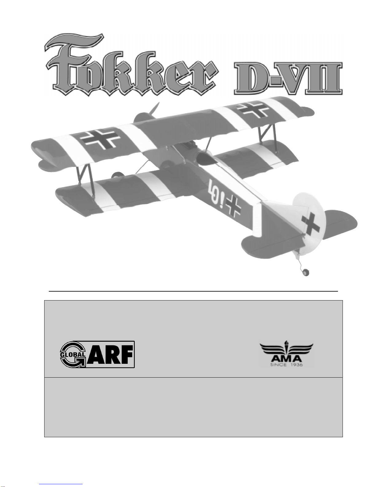
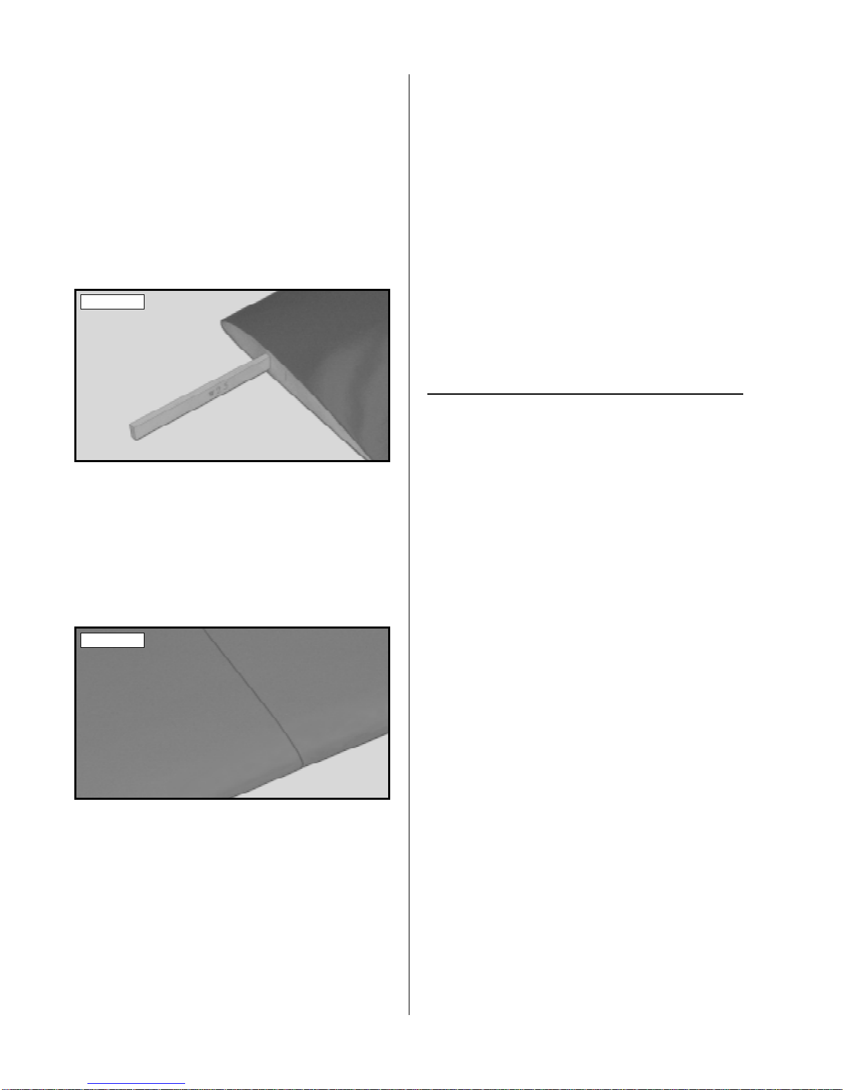
❑ 2) Using a straight edge ruler and a pen, locate
and mark the centerline of the plywood dihedral brace
(W-26). Draw one vertical line, on each side of the
brace, at this location. See photo # 1 below.
Photo # 1
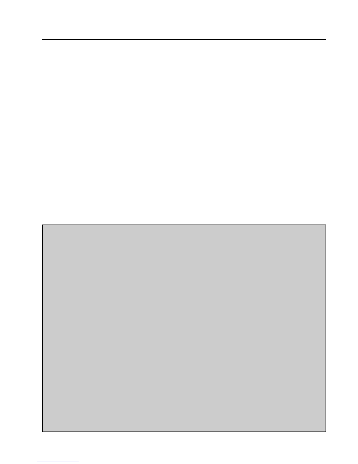
❑ 3) Test fit the plywood dihedral brace into the
plywood dihedral brace box in each wing half. The
brace should slide into each wing half up to its centerline. If it does not, remove the brace and lightly
sand the edges and tips until the proper fit is obtained.
See photo # 2 below.
Photo # 2
Removing most of the covering from the two
☛
root ribs will expose more of the wood. This will
result in a stronger joint when the wing halves are
epoxied together later.
6
Page 7
The dihedral brace is cut in the shape of a "V".
☛
The "V" shape should face the top surface of the wing
when the brace is installed.
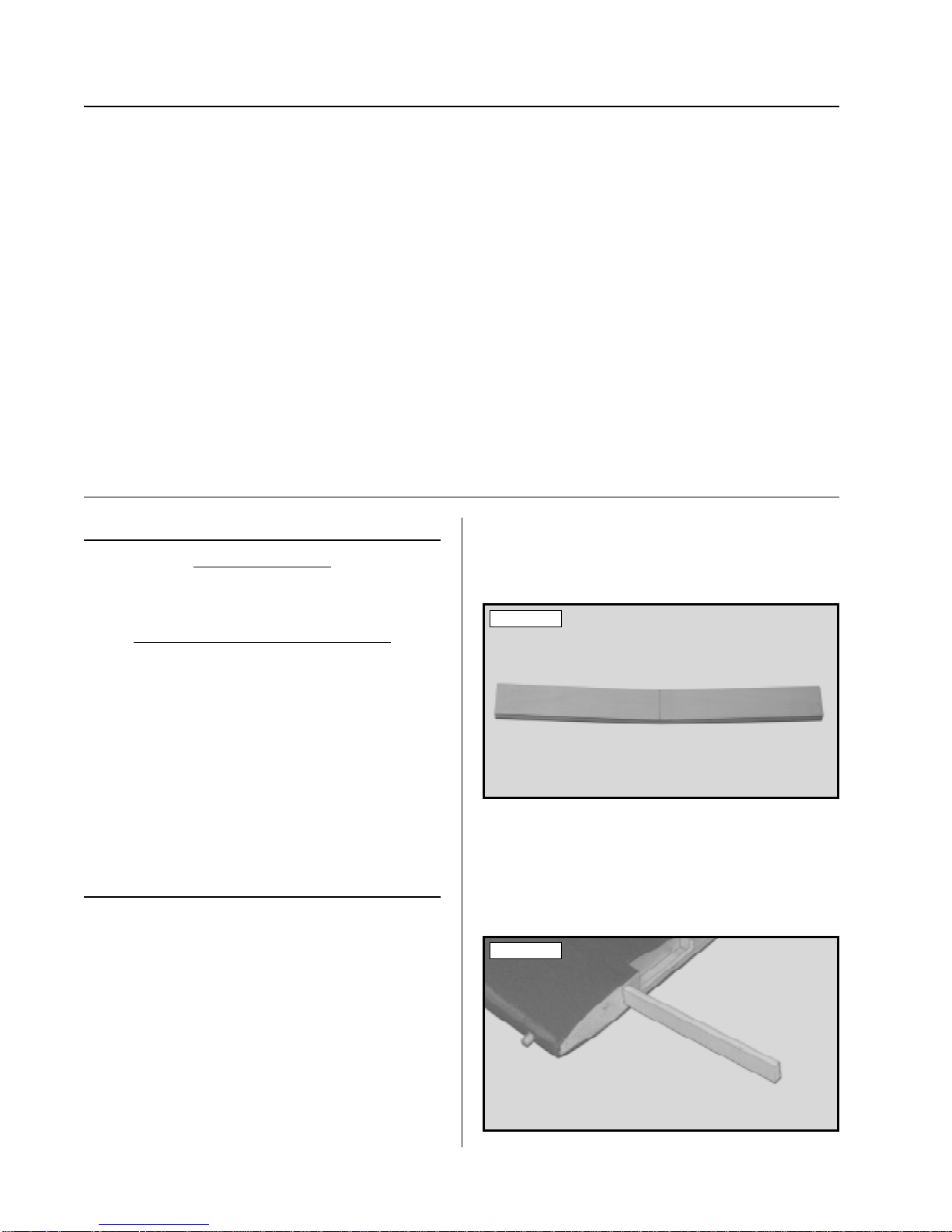
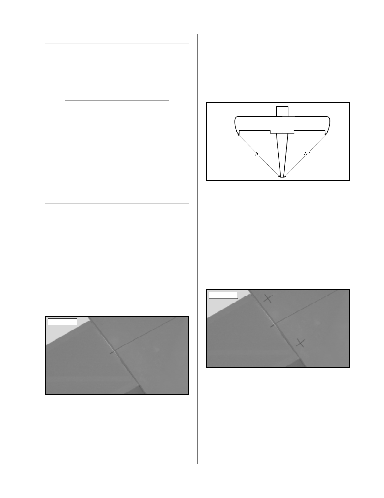
❑ 4) T est fit both of the wing halves together with
the dihedral brace temporarily installed (without using glue). Look carefully at the center section joint:
the wing halves should fit together tightly with few
or no gaps in the joint. See photo # 3 below.
Photo # 3
❑ 10) Mix a generous amount of Kwik Bond 30
Minute Epoxy. Apply a thin layer of epoxy to the
exposed half of the dihedral brace, the inside of the
second wing half, and the entire surface of both root
ribs. Make sure to use enough epoxy to fill any gaps.
❑ 11) Slide the two wing halves together and carefully align them at both the leading and trailing edges.
Wipe away any excess epoxy, using a paper towel
and rubbing alcohol, and use several pieces of masking tape to hold the two wing halves aligned until the
epoxy fully cures.
❑ 12) Once the epoxy has fully cured, doublecheck the center section joint. If any gaps are present,
mix a small amount of Kwik Bond 30 Minute Epoxy
and carefully fill any remaining gaps. Remove any
excess epoxy using a paper towel and rubbing alcohol, and allow the epoxy to thoroughly cure.
❑ 5) If the center section joint is not tight, remove
the wing halves and the dihedral brace, and lightly
sand the edges and tips of the brace. T est fit the wing
halves together with the dihedral brace installed again
and repeat until you are satisfied with the fit. Once
you are satisfied with the fit, remove the wing halves
and the dihedral brace.
It is important that the wing halves fit together
☛
properly. The better the fit, the stronger the center
section joint will be.
❑ 6) Following the instructions on the packaging,
mix a generous amount of Kwik Bond 30 Minute
Epoxy. Mix the epoxy for about 1 minute. This will
ensure that both parts are thoroughly incorporated.
❑ 7) Working with only one wing half for now,
apply a thin layer of epoxy inside the plywood dihedral brace box and to only half of the dihedral brace.
Make sure to cover the top and bottom, as well as the
sides, and use enough epoxy to fill any gaps.
❑ 8) Slide the dihedral brace into the wing half
up to its centerline. Remove any excess epoxy before it dries, using a paper towel and rubbing alcohol.
Allow the epoxy to fully cure before proceeding.
❑ 13) Once the epoxy has fully cured, carefully
remove the masking tape from the wing.
TOP WING ASSEMBLY
PARTS REQUIRED
❑ {1} Top Wing - Right & Left Halves
❑ {1} Top Wing Dihedral Brace (W-25)
TOOLS AND SUPPLIES REQUIRED
❑ Kwik Bond 30 Minute Epoxy
❑ Excel Modeling Knife
❑ Masking Tape
❑ Straight Edge Ruler
❑ Pen or Pencil
❑ 220 Grit Sandpaper w/Sanding Block
❑ Paper Towels
❑ Rubbing Alcohol
❑ NHP Epoxy Mixing Sticks
❑ NHP Epoxy Mixing Cups
INSTALLING THE DIHEDRAL BRACE
❑ 1) Look carefully at the surface of each root rib
on both wing halves. Notice how the excess covering material overlaps onto them. Using a modeling
knife, carefully trim and remove the excess from both
of the root ribs, leaving about 1/16" of covering material overlapping so it does not pull away later.
JOINING THE WING HALVES
❑ 9) Once the epoxy has fully cured, trial fit both
wing halves together again to double check that the
wing halves still fit together properly.
Removing most of the covering from the two
☛
root ribs will expose more of the wood. This will
result in a stronger joint when the wing halves are
epoxied together later.
7
Page 8
❑ 2) Using a straight edge ruler and a pen, locate
and mark the centerline of the plywood dihedral brace
(W-25). Draw one vertical line, on each side of the
brace, at this location.
❑ 6) Following the instructions on the packaging,
mix a generous amount of Kwik Bond 30 Minute
Epoxy . Mix the epoxy for about 1 minute. This will
ensure that both parts are thoroughly incorporated.
❑ 3) Test fit the plywood dihedral brace into the
plywood dihedral brace box in each wing half. The
brace should slide into each wing half up to its centerline. If it does not, remove the brace and lightly
sand the edges and tips until the proper fit is obtained.
See photo # 4 below.
Photo # 4
The dihedral brace is cut straight, so it doesn't
☛
matter which direction it is installed into the wing.
❑ 4) Test fit both of the wing halves together with
the dihedral brace temporarily installed (without using glue). Look carefully at the center section joint:
the wing halves should fit together tightly with few
or no gaps in the joint. See photo # 5 below.
Photo # 5
❑ 7) Working with only one wing half for now,
apply a thin layer of epoxy inside the plywood dihedral brace box and to only half of the dihedral brace.
Make sure to cover the top and bottom, as well as the
sides, and use enough epoxy to fill any gaps.
❑ 8) Slide the dihedral brace into the wing half
up to its centerline. Remove any excess epoxy before it dries, using a paper towel and rubbing alcohol.
Allow the epoxy to fully cure before proceeding.
JOINING THE WING HALVES
❑ 9) Once the epoxy has fully cured, trial fit both
wing halves together again to double check that the
wing halves still fit together properly.
❑ 10) Mix a generous amount of Kwik Bond 30
Minute Epoxy. Apply a thin layer of epoxy to the
exposed half of the dihedral brace, the inside of the
second wing half, and the entire surface of both root
ribs. Make sure to use enough epoxy to fill any gaps.
❑ 11) Slide the two wing halves together and carefully align them at both the leading and trailing edges.
Wipe away any excess epoxy using a paper towel
and rubbing alcohol and use several pieces of masking tape to hold the two wing halves aligned until the
epoxy fully cures.
❑ 5) If the center section joint is not tight, remove
the wing halves and the dihedral brace, and lightly
sand the edges and tips of the brace. T est fit the wing
halves together with the dihedral brace installed again
and repeat until you are satisfied with the fit. Once
you are satisfied with the fit, remove the wing halves
and the dihedral brace.
It is important that the wing halves fit together
☛
properly. The better the fit, the stronger the center
section joint will be.
8
❑ 12) Once the epoxy has fully cured, doublecheck the center section joint. If any gaps are present,
mix a small amount of Kwik Bond 30 Minute Epoxy
and carefully fill any remaining gaps. Remove any
excess epoxy , using a paper towel and rubbing alcohol, and allow the epoxy to thoroughly cure.
❑ 13) After the epoxy has fully cured, carefully
remove the masking tape from the wing. If any residue is left from the tape, it can be removed using a
paper towel soaked with a small amount of rubbing
alcohol.
Page 9
BOTTOM WING MOUNTING
PARTS REQUIRED
❑ 6) Remove the two ailerons from the wing and
set them aside for now.
❑ {1} Wing Bolt Doubler (W-30)
❑ {2} 4mm x 25mm Machine Screws
❑ {2} 4mm Flat Washers
❑ {2} 4mm Blind Nuts
TOOLS AND SUPPLIES REQUIRED
❑ Kwik Bond Thick C/A
❑ Excel Modeling Knife
❑ Ernst Airplane Stand
❑ Masking Tape
❑ Electric Drill
❑ 5/32" & 7/32" Drill Bits
❑ Straight Edge Ruler
❑ Phillips Head Screwdriver
❑ Needle Nose Pliers
❑ Pen or Pencil
ALIGNING THE WING
❑ 1) Set the fuselage upside down in your airplane
stand and place the bottom wing into the wing saddle.
Align the two hardwood dowels in the leading edge
of the wing with the two predrilled holes in the
fuselage's forward bulkhead.
❑ 2) Carefully slide the wing forward, making
sure that the two hardwood dowels fully engage the
two predrilled holes in the forward bulkhead.
❑ 3) Using a ruler and a pen, locate the centerline of the fuselage, at the back edge of the wing
saddle, and place a mark. See photo # 6 below.
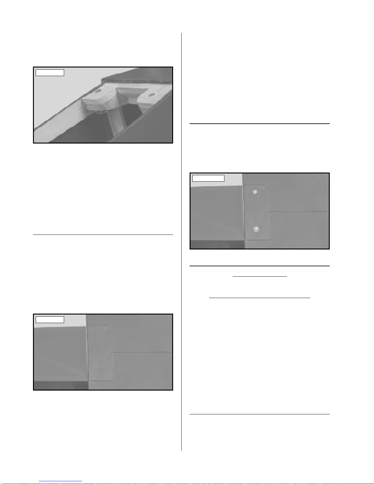
❑ 7) Check that the wing is square to the fuselage. To do this use a ruler and carefully measure
from the trailing edge of each wing tip to the back
edge of the fuselage. Both of these measurements
should be the same. See figure # 1 below.
Figure # 1
A = A-1
❑ 8) If the two measurements are not the same,
carefully lift the masking tape and adjust the back of
the wing until they are. When you are satisfied with
the alignment, reattach the masking tape to hold the
wing securely in place.
INSTALLING THE BLIND NUTS
❑ 9) Using a ruler and a pen, measure 3/8" in front
of the trailing edge of the wing and place two marks,
one on each side of the centerline. Now measure
1-9/32" out from each side of the centerline and place
two marks. See photo # 7 below.
Photo # 7
Photo # 6
❑ 4) The joint where the two wing halves were
glued together is the centerline of the wing. Align
the centerline of the wing with the centerline you drew
on the bottom of the fuselage.
❑ 5) While holding the wing in alignment, use a
couple of pieces of masking tape to hold the wing
securely to the fuselage.
❑ 10) Using a drill with a 5/32" drill bit, carefully
drill two holes into the wing and down through the
plywood wing hold down block inside the fuselage.
Angle the drill bit so that the holes will be per-
☛
pendicular to the bottom of the wing.
❑ 11) Remove the wing from the wing saddle.
Using a drill with a 7/32" drill bit, enlarge only the
two holes in the plywood mounting block.
9
Page 10
❑ 12) Install the two 4mm blind nuts into the bottom of the plywood mounting plate. Use a pair of
needle nose pliers to squeeze the blind nuts up into
place. See photo # 8 below.
Photo # 8
A balsa filler block has been preinstalled onto
☛
the bottom of the plywood plate to make it easier to
install the blind nuts.
❑ 18) Apply a generous amount of Kwik Bond
Thick C/A to the bottom of the doubler. Set the doubler back into place and realign it. Hold the doubler
firmly in place until the C/A fully cures.
❑ 19) Remove the wing from the wing saddle.
Using a drill with a 5/32" drill bit, drill the two wing
mounting screw holes through the wing bolt doubler.
Use the holes you drilled through the wing as a guide.
MOUNTING THE WING
❑ 20) Place the wing back into the wing saddle
and bolt it in place using the two 4mm x 25mm machine screws and two 4mm flat washers. Tighten the
screws firmly using a phillips head screwdriver. See
photo # 10 below.
❑ 13) With the blind nuts fully seated, carefully
apply a bead of Kwik Bond Thick C/A around the
bottom of each blind nut to lock them into place. Be
careful not to get any glue into the threads and allow
the C/A to fully cure before proceeding.
INSTALLING THE WING BOLT DOUBLER
❑ 14) Place the wing back into the wing saddle
and realign it. Use a couple of pieces of masking
tape to hold it in place.
❑ 15) Set the wing bolt doubler (W-30) in place
on the bottom of the wing. The back edge of the
doubler should be about 1/16" in front of the trailing
edge and the sides of the doubler should be even with
the sides of the fuselage. See photo # 9 below.
Photo # 9
❑ 16) While holding the wing bolt doubler in
place, use a pen and outline the doubler onto the wing.
Photo # 10
HORIZONTAL STABILIZER
PARTS REQUIRED
❑ {1} Horizontal Stabilizer w/Elevator & Hinges
TOOLS AND SUPPLIES REQUIRED
❑ Kwik Bond 30 Minute Epoxy
❑ Excel Modeling Knife
❑ Ernst Airplane Stand
❑ Masking Tape
❑ Straight Edge Ruler
❑ Pen or Pencil
❑ Builder's Triangle
❑ 220 Grit Sandpaper w/Sanding Block
❑ Paper Towels
❑ Rubbing Alcohol
❑ NHP Epoxy Mixing Sticks
❑ NHP Epoxy Mixing Cups
ALIGNING THE STABILIZER
❑ 17) Remove the doubler from the wing. Using
a modeling knife, carefully remove the covering from
inside the outline you drew.
10
❑ 1) Remove the elevator and hinges from the
horizontal stabilizer and set them aside for now.
Page 11
❑ 2) Using a ruler and a pen, locate and mark the
centerline of the horizontal stabilizer, at the trailing
edge, and place a mark. Using a builder's triangle,
extend this mark from front to back across the top
and bottom of the stabilizer.
❑ 3) Using a modeling knife, carefully remove the
covering from the tops of the stabilizer mounting sides
on the fuselage. See photo # 11 below.
Photo # 11
❑ 4) Mount the bottom wing to the fuselage. With
the fuselage securely in your airplane stand, set the
stabilizer onto the stabilizer mounting sides. The trailing edge of the stabilizer should be even with the
back edge of the fuselage.
❑ 5) Align the centerline mark on the trailing edge
of the stabilizer with the center of the back edge of
the fuselage. When that is aligned, hold the trailing
edge of the stabilizer in that position using a piece of
masking tape.
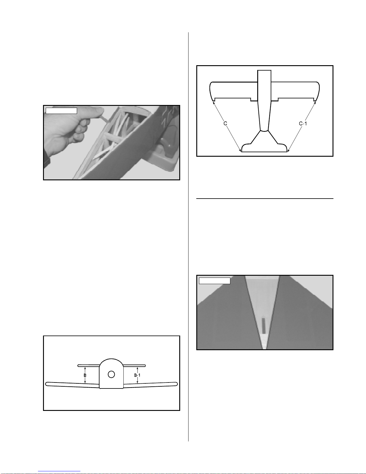
stabilizer tip on the same side. Do this for both
sides. When the stabilizer is aligned properly , both
of these measurements should be the same. See
figure # 3 below.
Figure # 3
C = C-1
❑ 8) When you are satisfied with the alignment,
hold the stabilizer firmly in place using a couple of
pieces of masking tape. Do not use glue yet!
MOUNTING THE STABILIZER
❑ 9) With the stabilizer held firmly in place, use a
pen to draw lines onto the bottom of the stabilizer
where it and the fuselage sides meet. Do this on both
the right and left sides.
❑ 10) Remove the stabilizer from the fuselage.
Using the lines you just drew as a guide, carefully
remove the covering from between them using a
modeling knife. See photo # 12 below.
❑ 6) With the stabilizer in place, look carefully
from the front of the fuselage at both the wing and
the stabilizer. When aligned properly, the stabilizer
should be level with the wing. If it is not level, use
220 grit sandpaper and a sanding block to sand down
the higher stabilizer mounting side until the correct
alignment is achieved. See figure # 2 below.
Figure # 2
B = B-1
❑ 7) Now check to make sure that the tips of the
stabilizer are equal distances from the tips of the wing.
Use a ruler and measure from one wing tip to the
Photo # 12
When cutting through the covering to remove
☛
it, cut with only enough pressure to cut through only
the covering itself. Cutting into the balsa will weaken
the stabilizer.
❑ 11) Mix a generous amount of Kwik Bond 30
Minute Epoxy. Apply a thin layer to the mounting
area on the bottom of the stabilizer and to the tops of
the stabilizer mounting sides and cross-member on
the fuselage.
11
Page 12
❑ 12) Set the stabilizer back into place and realign
it, double checking all of your measurements once
more. When satisfied with the alignment, hold the
stabilizer in place using several pieces of masking
tape and remove any excess epoxy using a paper towel
and rubbing alcohol before it cures. Allow the epoxy
to fully cure before proceeding.
VERTICAL STABILIZER
PARTS REQUIRED
❑ {1} Vertical Stabilizer w/Rudder & Hinges
❑ {2} Precovered Triangle Stock (RT-8)
TOOLS AND SUPPLIES REQUIRED
❑ Kwik Bond Thick C/A
❑ Kwik Bond 30 Minute Epoxy
❑ Excel Modeling Knife
❑ Ernst Airplane Stand
❑ Masking Tape
❑ Pen or Pencil
❑ Builder's Triangle
❑ Paper Towels
❑ Rubbing Alcohol
❑ NHP Epoxy Mixing Sticks
❑ NHP Epoxy Mixing Cups
lines you drew and from the bottom edge of the stabilizer. Also remove the covering from inside the
outline you drew on top of the horizontal stabilizer.
See photo # 13 below.
Photo # 13
When cutting through the covering to remove
☛
it, cut with only enough pressure to cut through only
the covering itself. Cutting into the balsa will weaken
the structure.
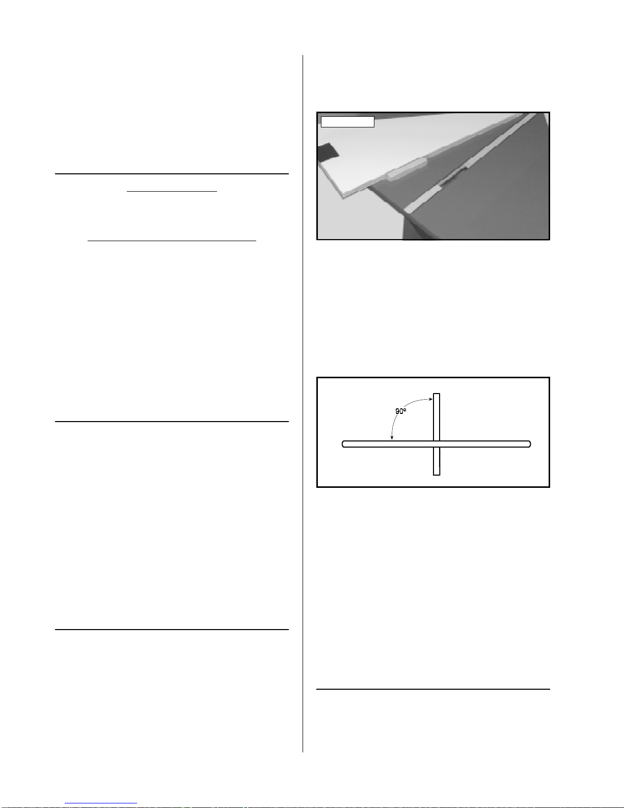
❑ 6) Set the vertical stabilizer back into place and
realign it. Using a builder's triangle, check to ensure
that the vertical stabilizer is aligned 90º to the horizontal stabilizer. See figure # 4 below.
Figure # 4
ALIGNING THE STABILIZER
❑ 1) Remove the rudder and the hinges from the
stabilizer and set them aside for now.
❑ 2) Using a modeling knife, remove the covering from over the top of the precut slot in the
horizontal stabilizer.
❑ 3) Set the vertical stabilizer in place, making
sure that the tab in the bottom of the stabilizer is
pushed down firmly into the precut slot. The front
of the stabilizer should also be lined up with the
centerline you drew previously on the horizontal
stabilizer.
MOUNTING THE STABILIZER
❑ 4) While holding the vertical stabilizer firmly
in place, use a pen to draw a line on each side of it
where it meets the top of the horizontal stabilizer.
Also draw a line on top of the horizontal stabilizer
around the base of the vertical stabilizer.
❑ 5) Remove the stabilizer. Using a modeling
knife, carefully remove the covering from below the
❑ 7) Mix a generous amount of Kwik Bond 30
Minute Epoxy. Apply a thin layer to the mounting
slot in the horizontal stabilizer and to the sides and
bottom of the vertical stabilizer mounting area. Also
apply epoxy to the top of the horizontal stabilizer.
❑ 8) Set the stabilizer back into place and realign
it, double checking all of your measurements. Hold
the stabilizer in place using several pieces of masking tape and remove any excess epoxy using a paper
towel and rubbing alcohol. Allow the epoxy to fully
cure before proceeding.
INSTALLING THE TRIANGLE STOCK
❑ 9) Using a modeling knife, remove the covering that overlaps onto the inner edges of the two pieces
of precovered triangle stock.
12
Page 13

❑ 10) W orking with one piece of triangle stock for
now, align it in the joint between the horizontal and
vertical stabilizers. When it's properly aligned, the
triangle stock should be even with the trailing edges
of the stabilizers. See photo # 14 below.
Photo # 14
❑ 11) When satisfied with the alignment, hold the
triangle stock in place and trace around it using a
pen.
❑ 12) Remove the triangle stock. Using a modeling knife, carefully remove the covering from inside
the outline you drew.
❑ 13) Glue the triangle stock into place using
Kwik Bond Thick C/A. Allow the C/A to cure completely before proceeding.
The triangle stock adds a lot of strength to the
☛
joint between the stabilizers. It is important that it be
glued in securely.
TOOLS AND SUPPLIES REQUIRED
❑ Kwik Bond 30 Minute Epoxy
❑ Pacer Blue Thread Lock
❑ Robart Incidence Meter
❑ Excel Modeling Knife
❑ Ernst Airplane Stand
❑ Masking Tape
❑ Electric Drill
❑ 5/64" & 1/8" Drill Bits
❑ Straight Edge Ruler
❑ Phillips Head Screwdriver
❑ Needle Nose Pliers
❑ Pen or Pencil
❑ NHP Epoxy Mixing Sticks
❑ NHP Epoxy Mixing Cups
INSTALLING THE CABANE STRUTS
Setting the proper wing incidence is important
☛
in any airplane; however, wing incidence is critical
in a biplane to achieve good flight performance. Incidence is the angle at which the flying surfaces (i.e.,
wings and stabilizer) flow through the air. The Fokker
D-VII should be set up with the stabilizer at 0º, the
bottom wing at 0º and the top wing at either 0º or -1º
incidence. We highly recommend that you use an
incidence meter to help you make these measurements. See figure # 5 below .
Figure # 5
❑ 14) Repeat steps # 10 - # 13 to install the second piece of triangle stock on the opposite side.
TOP WING MOUNTING
PARTS REQUIRED
❑ {4} Aluminum Cabane Struts (2 left & 2 right)
❑ {4} Aluminum Wing Mounts (2 left & 2 right)
❑ {2} Upper Strut Stabilizer Rods (1 left & 1 right)
❑ {2} Lower Strut Stabilizer Rods (1 left & 1 right)
❑ {2} Aluminum Strut Stabilizer Rod Clamps
❑ {2} Precovered Outer N-Struts
❑ {8} 3mm x 12mm Wood Screws
❑ {4} 3mm x 15mm Machine Screws
❑ {4} 3mm Nylon Insert Nuts
❑ {4} 3mm x 10mm Wood Screws
❑ {8} 3mm Blind Nuts
❑ {4} 3mm Split Washers
❑ {12}3mm x 10mm Machine Screws
❑ {12}3mm Flat Washers
❑ 1) Using a modeling knife, remove the cover-
ing from over the four predrilled holes in each side
of the fuselage. The first hole is located 5/8" back
from the firewall and 5/8" up from the bottom of the
fuselage. The second hole is located 5/8" back from
the firewall and 2-5/8" up from the bottom of the fuselage. The third and fourth holes are located 6-3/4"
and 11-1/2" back from the firewall and 5/8" down
from the start of the curve on the fuselage side.
❑ 2) Using a modeling knife, remove the covering from over the two predrilled holes in both ends
of each outer N-strut and the two predrilled holes in
each outer N-strut mounting tab on the bottom wing.
13
Page 14

The top wing does not have predrilled outer
☛
N-Strut mounting tabs.
❑ 3) Thread the two upper strut stabilizer rods
(shorter rods) into the two upper holes (one on each
side) in the front of the fuselage. Thread the rods
completely into place. When positioned properly the
bend in the top end of each rod should point down.
❑ 6) Install one aluminum wing mount onto each
of the two rear cabane struts using two 3mm x 10mm
machine screws, two 3mm split washers and two 3mm
nylon insert nuts. Do not completely tighten the
screws at this time.
Install the wing mounts on the outside of the
☛
cabane struts.
If the bends in the tops of the rods point up then
☛
the rods are on the wrong side of the fuselage.
❑ 4) Thread the two lower strut stabilizer rods
(longer rods) into the two lower holes (one on each
side) in the front of the fuselage. Thread the rods
completely into place. When positioned properly,
the bend in the top end of each rod should point up.
See photo # 15 below.
Photo # 15
❑ 5) Install the four aluminum cabane struts (2 left
& 2 right) onto the fuselage sides using four 3mm x
15mm machine screws and four 3mm flat washers.
Thread the screws through the elongated holes in each
strut and into the fuselage, but do not completely
tighten the screws at this time.
When installed properly, the cabane struts
☛
should be angled forward toward the firewall and
out from the fuselage sides. When you look at the
tops of the struts from the front of the fuselage the
struts should be nearly parallel with the fuselage
sides. If they are not, you may have them on the
wrong side. See figure # 6 below.
Figure # 6
❑ 7) Connect the two stabilizer strut rods on each
side of the fuselage to the two aluminum strut rod
clamps.
❑ 8) Install the two remaining aluminum wing
mounts to the two front cabane struts, along with the
two strut rod clamp assemblies. Use two 3mm x
10mm machine screws, two 3mm split washers and
two 3mm nylon insert nuts to secure them into place.
Do not completely tighten the screws at this time.
See photo # 16 below.
Photo # 16
INSTALLING THE OUTER N-STRUTS
❑ 9) Test fit the outer N-struts to the mounting
tabs on the bottom wing. The struts are universal
from right to left, but there is a difference between
the top and the bottom. If the holes in the mounting
tabs do not line up with the holes in the N-strut, turn
the N-strut over.
The N-struts should be installed on the inside of
☛
the mounting tabs.
❑ 10) When satisfied with the alignment, bolt the
outer N-struts to the bottom wing using four 3mm x
10mm machine screws, four 3mm flat washers and
four 3mm blind nuts. Tighten the screws firmly to
draw the blind nuts into place.
14
The blind nuts should be installed on the inside
☛
of the N-struts.
Page 15

ALIGNING THE TOP WING
❑ 11) Install the bottom wing onto the fuselage.
Set the fuselage in your airplane stand and use a
couple of large rubber bands or small weights to hold
the airplane firmly in place. It's important that the
fuselage not move during the remaining wing alignment process.
It may be necessary to bend or change the angle
☛
of the cabane struts to help align the wing.
❑ 15) At this point the top wing should be cen-
tered on the fuselage and parallel with the bottom
wing. Double check the incidence of the top wing.
It should be between 0º and -1º.
❑ 12) Attach your incidence meter to the bottom
wing. Adjust the airplane stand and/or fuselage until
the incidence meter reads 0º. See photo # 17 below.
Photo # 17
It may be necessary to use a block of wood or a
☛
book to prop up one end of the airplane stand. If you
need to prop it up, make sure it is secure. It's important that the stand doesn't move.
❑ 13) Set the top wing onto the cabane struts and
the outer N-struts. Use clothespins or small clamps
to hold the tops of the N-struts to the N-strut mounting tabs on the top wing. Pieces of masking tape will
work, too.
Make sure the N-struts are located on the inside
☛
of the strut mounting tabs.
❑ 14) Attach your incidence meter to the top wing.
Carefully adjust the cabane struts and aluminum
wing mounts until the incidence meter reads approximately 0º. When satisfied with the alignment,
tighten the cabane strut mounting screws only tight
enough so that the struts won't move easily. See
photo # 18 below.
Photo # 18
MOUNTING THE TOP WING
❑ 16) When satisfied with the alignment, use a pen
to mark the locations of the four N-Strut mounting
holes onto the mounting tabs on the top wing.
❑ 17) Remove the top wing and lay it upside down
on your work table. Using a 1/8" drill bit, carefully
drill the four holes through the N-strut mounting tabs.
Lay a towel over the wing to protect it while
☛
you drill the holes.
❑ 18) Set the top wing back into place and realign
it. Bolt the N-struts into place using four 3mm x
10mm machine screws, four 3mm flat washers and
four 3mm blind nuts. Tighten the screws firmly to
draw the blind nuts into place.
The blind nuts should be installed on the inside
☛
of the N-struts.
❑ 19) Reattach the incidence meter to the top
wing and double check the incidence. It should still
be between 0º and -1º. If it is not, remove the Nstruts and make small adjustments to the mounting
holes in the N-strut mounting tabs until the alignment is correct.
Wing alignment is important, but the integrity
☛
of the joints is also important. Be careful not to enlarge the N-strut mounting holes any more than
necessary. If there is too much play, the wing could
shift during flight.
❑ 20) With the top wing bolted to the N-struts, use
a pen and mark the screw locations of the four aluminum wing mounts onto the bottom of the wing.
❑ 21) Remove the top wing. Using a drill with a
5/64" drill bit, drill eight pilot holes into the wing at
the locations you marked.
Be careful not to drill through the top of the
☛
wing!
15
Page 16

❑ 22) One at a time, remove the aluminum wing
mounts from the cabane struts and install them into
their proper positions on the wing. Use eight 3mm x
12mm wood screws to secure them into place. See
photo # 19 below.
❑ 28) Mix a small quantity of Kwik Bond 30
Minute Epoxy. One at a time, remove the wood
screws that hold the aluminum wing mounts to the
top wing, apply a dab of epoxy to the screws, then
reinstall and tighten them securely .
Photo # 19
❑ 23) Install the top wing and check the alignment
one more time using your incidence meter. If the
wing is out of alignment loosen the four machine
screws that hold the cabane struts to the fuselage sides.
Adjust the cabane struts until you are satisfied with
the alignment and retighten the screws.
❑ 24) When you're satisfied with the alignment,
remove the four screws (one at a time) and reinstall
them using a couple of drops of Pacer Thread Lock.
Tighten the screws firmly to secure them in place.
Do not apply any thread lock to the outer N-strut
☛
mounting screws or to the screws that hold the aluminum wing mounts to the cabane struts.
❑ 25) Using a 5/64" drill bit, drill four pilot holes
into the fuselage sides using the predrilled holes in
the cabane struts (above the elongated holes) as a
guide.
The epoxy will secure the screws in place and
☛
prevent any chance of them loosening during flight.
CONTROL SURFACE HINGING
TOOLS AND SUPPLIES REQUIRED
❑ Kwik Bond Thin C/A
❑ Kwik Bond 30 Minute Epoxy
❑ Excel Modeling Knife
❑ Scissors
❑ Waxed Paper
❑ NHP Epoxy Mixing Sticks
❑ NHP Epoxy Mixing Cups
HINGING THE AILERONS
❑ 1) Locate the precut hinge slots in the trailing
edge of each half of the wing and the leading edge of
each aileron.
❑ 2) Using a modeling knife, carefully remove any
excess covering material from over each of the hinge
slots.
❑ 3) T est fit the C/A hinges into the hinge slots in
one aileron. Each hinge should be inserted far enough
into the slots so that the centerline of the hinges is
flush with the leading edge of the aileron. If the hinges
cannot be inserted deeply enough, use a modeling
knife and carefully cut the hinge slots deeper.
❑ 26) Install four 3mm x 10mm wood screws
through the predrilled holes in the cabane struts and
into the fuselage sides. Tighten the screws firmly.
These wood screws will lock the cabane struts
☛
in place, preventing them from moving back and forth
after you have removed the top wing.
❑ 27) Remove the top wing. T o do this properly,
first remove the four machine screws from the upper
N-strut mounts, then remove the four machine screws
and nylon insert nuts that hold the aluminum wing
mounts to the cabane struts.
16
❑ 4) With each of the hinges centered in the hinge
slots, apply 3-4 drops of Kwik Bond Thin C/A to the
joint where the hinges and the aileron meet. Allow a
few seconds between drops for the C/A to wick into
the hinges, then turn the aileron over and repeat this
procedure on the other side of each hinge. Let the
C/A dry for about 10 minutes before proceeding.
❑ 5) Using a pair of scissors, cut out a small
piece of waxed paper. Working with one wing half
for now, slide the waxed paper between the aileron torque rod and the trailing edge of the wing.
See photo # 20 at top right.
Page 17

Photo # 20
The waxed paper will prevent epoxy from glu-
☛
ing the torque rod to the trailing edge of the wing.
❑ 6) Using a modeling knife, carefully remove
the covering from over the predrilled hole and the
precut groove in the leading edge of the aileron.
❑ 7) Mix a small quantity of Kwik Bond 30
Minute Epoxy. Apply a thin layer of epoxy to the
aileron torque rod, and pack epoxy into the predrilled
hole and the precut groove in the leading edge of
the aileron.
❑ 8) Slide the aileron and its hinges into the hinge
slots in the trailing edge of the wing, making sure
that the torque rod is firmly seated in the leading edge
of the aileron. Adjust the aileron so the ends of the
aileron don't rub against the wing.
❑ 9) While holding the aileron tight against the
wing, rotate the aileron down about 45º. Apply 3-4
drops of Kwik Bond Thin C/A to the exposed area
of each hinge. Turn the wing over and repeat for
the other side of the hinges. Allow the C/A and
epoxy to fully cure. Once cured, the aileron may be
stiff and difficult to move. This is normal. Gently
move the aileron up and down about five to ten times
to free it up.
❑ 10) Repeat steps # 3 - # 9 to install the second
aileron onto the other half of the wing.
HINGING THE ELEVATOR
q 13) Test fit the C/A hinges into the hinge slots in
the elevator. Each hinge should be inserted far enough
into the slots so that the centerline of the hinges are
flush with the leading edge. If the hinges cannot be
inserted deeply enough, use a modeling knife to carefully cut the hinge slots deeper.
❑ 14) With each of the hinges centered, apply 3-4
drops of Kwik Bond Thin C/A to the joint where the
hinges and the elevator meet. Allow a few seconds
between drops for the C/A to wick into the hinges,
then turn the elevator over and repeat this procedure
on the other side. Let the C/A dry for about 10 minutes before proceeding.
❑ 15) Slide the elevator and its hinges into the
precut hinge slots in the trailing edge of the stabilizer. Adjust the elevator so that the elevator tips are
even with the stabilizer tips.
❑ 16) While holding the elevator tight against the
stabilizer, rotate the elevator down about 45º. Apply
3-4 drops of Kwik Bond Thin C/A to the exposed
area of each hinge. Turn the fuselage over and repeat for the other side of the hinges. Allow the C/A
to cure for about 10 minutes. Once cured, the elevator may be stiff and difficult to move. This is normal.
Gently move it up and down about five to ten times
to free it up.
HINGING THE RUDDER
❑ 17) Locate the precut hinge slots in the trailing
edge of the vertical stabilizer and the leading edge of
the rudder. A hinge slot is also located in the back
edge of the fuselage, below the horizontal stabilizer.
❑ 18) Test fit the C/A hinges into the hinge slots
in the rudder. Each hinge should be inserted far
enough into the hinge slots so that the centerline of
the hinges are flush with the leading edge. If the
hinges cannot be inserted deeply enough, use a modeling knife to carefully cut the hinge slots deeper.
❑ 11) Locate the precut hinge slots in the trailing
edge of the horizontal stabilizer and the leading edge
of the elevator.
❑ 12) Using a modeling knife, carefully remove
any excess covering material from over each of the
hinge slots.
❑ 19) With each of the hinges centered, apply 3-4
drops of Kwik Bond Thin C/A to the joint where the
hinges and the rudder meet. Allow a few seconds
between drops for the C/A to wick into the hinges,
then turn the rudder over and repeat this procedure
on the other side. Let the C/A dry for a few minutes
before proceeding.
17
Page 18

❑ 20) Using a modeling knife, remove the covering from over the precut notch in the leading edge of
the rudder. This notch allows room for the rudder to
clear the elevator joiner.
❑ 21) Slide the rudder and its hinges into the precut hinge slots in the trailing edge of the vertical
stabilizer. Adjust the height of the rudder so it does
not rub against the top of the vertical stabilizer.
Check that when you move the elevator up and
☛
down and the rudder right and left, the notch in the
rudder does not interfere with the elevator joiner.
❑ 22) While holding the rudder tight against the
stabilizer, rotate the rudder to the side about 45º.
Apply 3-4 drops of Kwik Bond Thin C/A to the exposed area of each hinge. Turn the fuselage over
and repeat for the other side of the hinges. Allow
the C/A to cure for about ten minutes. Once cured,
the rudder may be stiff and difficult to move. This
is normal. Gently move it back and forth about five
to ten times to free it up.
TAIL WHEEL INSTALLATION
PARTS REQUIRED
❑ {1} Prebent Tail Wheel Wire
❑ {1} 25mm Diameter Wheel
❑ {1} Nylon Mounting Bracket
❑ {1} Nylon Steering Arm
❑ {2} 1.5mm Wheel Collars
❑ {2} 3mm x 6mm Machine Screws
❑ {3} 3mm x 12mm Wood Screws
❑ {1} 2mm x 10mm Wood Screw
TOOLS AND SUPPLIES REQUIRED
❑ Ernst Airplane Stand
❑ Masking Tape
❑ Electric Drill
❑ 1/16" & 5/64" Drill Bits
❑ Phillips Head Screwdriver
❑ Wire Cutters
❑ Pen or Pencil
❑ 2) Thread one 3mm x 6mm machine screw
through the side of the nylon arm and into the wheel
collar. Do not tighten the screw at this time.
❑ 3) Slide the prebent tail wheel wire up through
the bottom of the nylon bracket, then slide the nylon
steering arm over the wire. Make sure that the mounting clasp is facing the bottom of the bracket. See
photo # 21 below.
Photo # 21
❑ 4) Push the tail wheel wire into the bracket until the bend in the wire fits into the recessed area in
the bracket, and adjust the wire so that it is parallel
with the steering arm.
❑ 5) When satisfied with the alignment, tighten
the 3mm x 6mm machine screw to secure the wire in
place. Cut off the excess wire flush with the top of
the steering arm, using a pair of wire cutters.
MOUNTING THE TAIL WHEEL BRACKET
❑ 6) T est fit the tail wheel bracket assembly onto
the bottom of the fuselage. To align the bracket
properly , be sure that the tail wheel wire is even with
the rudder hinge line and that the nylon bracket is
aligned with the centerline of the fuselage. The nylon clasp in the steering arm slides over the bottom
of the rudder.
It will be necessary to bend the nylon steering arm
☛
down so the clasp will engage the rudder properly.
❑ 7) While holding the mounting bracket in place,
use a pen to mark the locations of the three mounting
holes onto the bottom of the fuselage.
TAIL WHEEL BRACKET ASSEMBLY
❑ 1) Insert one 1.5mm wheel collar into the top
of the nylon steering arm, making sure that the
threaded hole in the side of the wheel collar lines up
with the predrilled hole in the side of the nylon arm.
18
❑ 8) Remove the bracket. Using a drill with a
5/64" drill bit, drill three pilot holes through the bottom of the fuselage at the marks you made. Set the
bracket back into place and secure it to the fuselage
using three 3mm x 12mm wood screws.
Page 19

❑ 9) Place a couple of pieces of masking tape between the rudder and the vertical stabilizer to hold
the rudder centered. Using a drill with a 1/16" drill
bit, carefully drill a hole through the rudder to accept the mounting screw for the nylon clasp. Use the
predrilled holes in the clasp as a guide.
It will be necessary to bend the nylon steering arm
☛
down so the clasp will engage the rudder properly.
❑ 10) To secure the steering arm to the rudder , use
one 2mm x 10mm wood screw threaded into the predrilled hole in one side of the clasp, through the
rudder, and into the predrilled hole in the opposite
side of the clasp. Tighten the screw , but do not overtighten it. Y ou don't want to crush the wood or break
the clasp. See photo # 22 below.
Photo # 22
INSTALLING THE TAIL WHEEL
MAIN GEAR INSTALLATION
PARTS REQUIRED
❑ {2} Wire Spoke Main Gear Wheels
❑ {1} Precovered Landing Gear Wing
❑ {1} Wire Landing Gear Strut
❑ {2} Nylon Landing Gear Strap - Small Slot
❑ {2} Nylon Landing Gear Strap - Large Slot
❑ {8} 3mm x 12mm Wood Screws
❑ {2} Nylon Wheel Spacers
❑ {2} Wheel Collars w/3mm x 6mm Set Screws
❑ {2} Nylon Landing Gear Wing Mounts
❑ {2} 3mm x 6mm Machine Screws
❑ {4} 2mm x 5mm Wood Screws
❑ {1} Precovered Square Stock
TOOLS AND SUPPLIES REQUIRED
❑ Kwik Bond 5 Minute Epoxy
❑ Robart Incidence Meter
❑ Excel Modeling Knife
❑ Ernst Airplane Stand
❑ Electric Drill
❑ 1/16" & 5/64" Drill Bits
❑ Straight Edge Ruler
❑ Phillips Head Screwdriver
❑ Pen or Pencil
❑ Paper Towels
❑ Rubbing Alcohol
❑ NHP Epoxy Mixing Sticks
❑ NHP Epoxy Mixing Cups
❑ 11) Slide the 25mm diameter tail wheel onto the
tail wheel wire. Thread one 3mm x 6mm machine
screw into the wheel collar, then slide the wheel collar up against the tail wheel.
❑ 12) Slide the wheel collar on enough so it is up
against the tail wheel, but not so tight that the tail
wheel won't turn. The tail wheel should rotate without binding. When you are satisfied with the
alignment, securely tighten the machine screw using
a phillips screwdriver. See photo # 23 below.
Photo # 23
INSTALLING THE GEAR BRACKET
❑ 1) Place the wire landing gear bracket onto the
bottom of the fuselage. To align the bracket properly, the larger diameter wire should be toward the
front of the fuselage and the smaller diameter rear
wire should be positioned 11/16" in front of the wing
saddle.
❑ 2) While holding the gear bracket in position,
place the two nylon small-slot landing gear straps over
the rear wire and the two large-slot landing gear
straps over the front wire. Adjust them so that the
center of each strap is 1/2" in from the fuselage sides.
❑ 3) Using a pen, mark the locations of the eight
mounting holes onto the bottom of the fuselage.
❑ 4) Remove the nylon straps and the gear bracket.
Using a 5/64" drill bit, drill pilot holes through the
fuselage at the eight locations you marked.
19
Page 20

❑ 5) Set the gear bracket back into place and realign it. Install the four nylon straps using eight
3mm x 12mm wood screws. Tighten the screws
firmly to secure the gear bracket into place. See
photo # 24 below.
Photo # 24
INSTALLING THE GEAR WING
❑ 6) Using a modeling knife, remove the covering from over the precut slot in the top of the gear
wing. Also remove the covering from over both ends
of the slot. See photo # 25 below.
Photo # 25
❑ 10) Remove the gear wing from the wire. Using a drill with a 1/16" drill bit, drill four pilot holes
into the ends of the gear wing at the four locations
you marked previously.
❑ 11) Place the gear wing back onto the wire and
realign it. Secure the two nylon mounts to the ends
of the gear wing using four 2mm x 5mm wood
screws. See photo # 26 below.
Photo # 26
❑ 12) Partially thread two 3mm x 6mm machine
screws into the bottoms of the two nylon gear wing
mounts.
❑ 13) Using your incidence meter, carefully set the
incidence of the gear wing to 0º or -1º. When satisfied with the alignment, tighten the machine screws
in the nylon mounts to secure the gear wing into position.
❑ 7) Set the gear wing onto the wire between the
two landing gear axles, making sure that the slot in
the gear wing faces up.
❑ 8) Slide one nylon gear wing mount onto each
landing gear axle and push them up against the ends
of the gear wing.
Make sure the flat sides of both nylon mounts
☛
are up against the edges of the gear wing and that the
holes for the set screws are facing the bottom of the
gear wing.
❑ 9) Adjust the nylon mounts so that the two
mounting holes are parallel to the bottom of the wing.
While holding the mounts in place, use a pen and
mark the locations of the mounting holes onto the
edges of the gear wing.
❑ 14) Mix a small amount of Kwik Bond 5 Minute
Epoxy . Apply a thin layer of epoxy to the precovered
square stock and press the stock into the slot in the
top of the gear wing. Remove any excess epoxy using a paper towel and rubbing alcohol and allow the
epoxy to cure before proceeding.
INSTALLING THE MAIN GEAR WHEELS
❑ 15) Push one nylon spacer onto each of the two
landing gear axles. Push the spacers up against the
nylon gear wing mounts.
❑ 16) Slide one wheel onto each axle. Push the
wheels up against the nylon spacers, then slide one
wheel collar onto each axle and push them up against
the wheels. Adjust the depths of the wheel collars
until the wheels spin without binding, then tighten
the machine screws using a phillips screwdriver.
You may wish to apply a thin layer of grease to
☛
the axles to prevent the wheels from squeaking.
20
Page 21

ENGINE INSTALLATION
PARTS REQUIRED
❑ {2} Nylon Motor Mount Beams
❑ {4} 3mm x 20mm Machine Screws
❑ {4} 3mm x 25mm Machine Screws
❑ {4} 3mm Nylon Insert Nuts
❑ {4} 3mm Blind Nuts
❑ {12} 3mm Flat Washers
❑ {1} 1.5mm x 350mm Wire w/Z-Bend
TOOLS AND SUPPLIES REQUIRED
❑ Ernst Airplane Stand
❑ Electric Drill
❑ 1/8", 5/32" and 1/4" Drill Bits
❑ Straight Edge Ruler
❑ Phillips Head Screwdriver
❑ Needle Nose Pliers
❑ Pen or Pencil
❑ 4) Install the engine onto the mounting beams
using four 3mm x 25mm machine screws, eight 3mm
flat washers and four 3mm lock nuts. Tighten the
screws and nuts completely to hold the engine firmly
in place.
ALIGNING THE MOTOR MOUNT
Whether you are using a two or a four cycle
☛
engine, the engine will be mounted at an angle (as
described below) so that the muffler assembly will
clear the side of the fuselage.
❑ 5) Using a ruler and a pen, draw a vertical
centerline on the firewall.
❑ 6) Using a ruler and a pen, measure up from the
bottom of the firewall 2-1/16" and draw a horizontal
line at this point.
MOUNTING THE ENGINE TO THE
MOTOR MOUNT BEAMS
❑ 1) Using a clamp or a vise, align the two nylon
motor mount beams and clamp them together. The
beam halves are universal and the webbing should
face the outside edges. It's also important that the
back edges of both beams be perfectly even. See
photo # 27 below.
Photo # 27
❑ 2) Using a ruler and a pen, mark the locations
of the four engine mounting holes onto the two beams.
So that the engine will line up properly with the front
of the cowl (when it is installed later), it is important
that the front edge of the engine's drive washer be
4-1/4" in front of the rear edge of the mounting beams.
The point at which these two lines intersect is
☛
the crankshaft centerline point.
❑ 7) Using a ruler and pen, measure up 5/8" from
the horizontal line (at the right side of the fuselage)
and place a mark. Measure down 5/8" from the horizontal line (at the left side of the fuselage) and place
a mark. Draw a straight line connecting these two
marks. See photo # 28 below.
Photo # 28
❑ 8) Using a ruler and pen, draw a line through
the crankshaft centerline point, perpendicular to the
angled line you just drew. See photo # 29 below.
Photo # 29
❑ 3) When satisfied with the alignment, remove
the beams from the clamp. Using a drill with a 1/8"
drill bit, drill four holes through the mounting beams
at the marks you made.
Make sure that you drill the holes straight down
☛
through the beams and not at an angle.
21
Page 22

❑ 9) Using a ruler and a pen, measure up 3/16"
from the angled horizontal line you drew and draw a
line parallel to it.
❑ 14) Hold the motor mount/engine assembly up
to the firewall (the motor is mounted upright). Double
check that the four predrilled holes in the motor mount
beams line up with the four intersecting lines.
❑ 10) Using a ruler and a pen, measure 1/8" to the
right of the perpendicular line you drew and draw a
line parallel to it. See photo # 30 below.
Photo # 30
❑ 11) Using a ruler and a pen, measure 15/32" up
from the second angled horizontal line and draw a
line parallel to it. Now measure down 1-7/16" from
the second angled horizontal line and draw a second
line parallel to it.
❑ 12) Using a ruler, measure the width between
the predrilled mounting holes in the backs of the two
motor mount beams. See photo # 31 below.
Notice that the motor assembly is offset from
☛
the centerline to compensate for the built-in right and
down thrust in the firewall. Offsetting the engine
ensures that the crankshaft lines up with the cowl.
MOUNTING THE ENGINE
TO THE FIREWALL
❑ 15) When satisfied with the alignment, use a
drill with a 5/32" drill bit and drill four holes through
the firewall for the motor mount screws.
❑ 16) Hold the motor mount/engine assembly up
to the firewall and align it with the mounting holes.
Using a pencil, mark the location of the throttle pushrod exit hole onto the firewall.
If you are using a 2 cycle engine, the throttle
☛
pushrod exit hole should be about 1/4" above the top
motor mount hole. If you are using a 4 cycle engine,
the throttle pushrod exit hole should be right behind
the throttle arm.
Photo # 31
❑ 13) Divide the measurement found in step # 12
in half. Using a ruler and a pen, measure this resulting distance and draw one line to the right and
one to the left of the second angled vertical line.
See photo # 32 below.
Photo # 32
❑ 17) Using a drill with a 1/4" drill bit, drill a hole
through the firewall for the throttle pushrod wire at
the mark you made.
❑ 18) Attach the Z-bend in the 1.5mm x 350mm
throttle pushrod wire into the outermost hole in the
engine's throttle arm.
❑ 19) Slide the plain end of the pushrod wire
through the pushrod exit hole and install the motor
mount/engine assembly using four 3mm x 20mm
machine screws, four 3mm flat washers and four 3mm
blind nuts. Tighten the screws firmly to draw the
blind nuts into place. See photo # 33 below.
Photo # 33
22
Page 23

FUEL TANK
❑ 5) Using the Magnum Tubing Bender, carefully
bend the longer of the two tubes up at a 45º angle.
PARTS REQUIRED
❑ {1} Molded Fuel Tank
❑ {1} Rubber Stopper
❑ {1} 20mm Diameter Front Plate
❑ {1} 17mm Diameter Back Plate
❑ {1} 3mm x 18mm Machine Screw
❑ {1} Weighted Fuel Pick-Up
❑ {3} Aluminum Tubes
❑ {1} Silicon Fuel Tubing
TOOLS AND SUPPLIES REQUIRED
❑ Wilhold Silicon Sealant
❑ Magnum Tubing Bender
❑ Straight Edge Ruler
❑ Phillips Head Screwdriver
❑ Scissors
❑ 220 Grit Sandpaper w/Sanding Block
STOPPER ASSEMBLY
❑ 1) The fuel tank assembly incudes 3 different
length aluminum tubes. Discard the shortest of the
three tubes. It will not be used.
When the stopper assembly is installed in the
☛
fuel tank, the top of the vent tube should rest inside
the bubble in the top of the tank.
❑ 6) Secure one end of the silicon fuel tubing onto
the end of the weighted fuel pick-up.
❑ 7) Slide the silicon fuel tubing, with the fuel
pick-up attached, onto the end of the aluminum fuel
pick-up tube (straight tube). While holding the aluminum tube in place, adjust the length of the silicon
tubing until the fuel pick-up is 4-3/8" back from the
rear of the stopper assembly. See photo # 35 below .
Photo # 35
❑ 2) Using 220 grit sandpaper, carefully smooth
each end of the two remaining tubes. This will prevent the fuel tubing from being accidentally cut when
it is installed later.
❑ 3) Push the two aluminum tubes through the
rubber stopper. Slide the 20mm diameter front plate
over the tubes at the front of the stopper and slide the
17mm diameter back plate over the tubes at the rear
of the stopper.
❑ 4) Using a ruler, measure the distance that the
two aluminum tubes protrude from the front of the
stopper assembly. This distance should be 3/8". If it
is not, adjust the tubes by pushing them forward or
backward until you are satisfied with the alignment.
See photo # 34 below.
Photo # 34
❑ 8) Push the 3mm x 18mm machine screw
through the center hole in the front of the stopper
assembly and partially thread it into the metal stopper back plate. See photo # 36 below.
Photo # 36
INSTALLING THE STOPPER ASSEMBLY
❑ 9) Carefully push the stopper assembly into the
molded hole in the front of the fuel tank. Gently rotate the stopper assembly until the aluminum vent
tube rests inside the molded bubble in the top of the
fuel tank.
If you have trouble seeing the vent tube, hold
☛
the fuel tank assembly up to a bright light. This will
illuminate the inside of the tank.
23
Page 24

❑ 10) When satisfied with the alignment of the
stopper assembly, tighten the machine screw using a
phillips screwdriver until the rubber stopper expands
and seals the fuel tank opening. Do not overtighten
the screw. This could cause the front of the fuel tank
to split.
INSTALLING THE FUEL TANK
❑ 11) Carefully apply a generous bead of silicon
sealant onto the front of the fuel tank.
❑ 12) Slide the fuel tank into place, making sure
that the stopper assembly fits into the predrilled hole
in the firewall. When aligned properly, the front of
the tank should be pushed firmly against the back of
the firewall and the bottom of the tank should rest on
the fuel tank support floor.
When installing the fuel tank, make sure that
☛
the molded bubble in the top of the tank faces the top
of the fuselage.
the two preinstalled balsa support rails glued to the
fuselage sides. Position the tray so that the front edge
of the tray is 1-1/2" behind the forward bulkhead.
See photo # 37 below.
Photo # 37
❑ 2) When satisfied with the fit, use a pencil and
mark the location of the servo tray . Remove the tray
and apply a thick bead of Kwik Bond Thick C/A to
the top of the two balsa support rails only where the
servo tray will be glued.
❑ 13) Using a pair of scissors, cut out large
pieces of Dubro Foam Rubber. With the fuel tank
aligned, wedge the pieces of foam rubber between
the fuel tank and the fuselage to secure the fuel tank
into position.
Make sure that the foam rubber does not inter-
☛
fere with the throttle pushrod wire.
SERVO INSTALLATION
PARTS REQUIRED
❑ {1} Aileron Servo Tray (W-9C)
❑ {1} Rear Aileron Servo Tray Block (W-9B)
❑ {1} Front Aileron Servo Tray Block (W-9A)
❑ {1} Fuselage Servo Tray (D-38)
TOOLS AND SUPPLIES REQUIRED
❑ Kwik Bond Thick C/A
❑ Excel Modeling Knife
❑ Ernst Airplane Stand
❑ Electric Drill
❑ 1/16" Drill Bit
❑ Straight Edge Ruler
❑ Phillips Head Screwdriver
❑ Pen or Pencil
❑ 3) Set the servo tray back into place and realign
it. Hold the servo tray firmly in place until the C/A
fully cures.
INSTALLING THE AILERON SERVO TRAY
❑ 4) Position the two aileron servo tray mounting blocks onto the bottom wing. Block W-9A is
for the front and block W-9B is for the back. Both
blocks should be centered from side-to-side and their
inside edges should be even with the edges of the
servo opening. See photo # 38 below.
Photo # 38
Notice that one side of block W-9B is cut at an
☛
angle. The taller side of the block should be toward
the trailing edge of the wing.
INSTALLING THE FUSELAGE SERVO TRAY
❑ 1) Test fit the fuselage servo tray (D-38) onto
24
❑ 5) When satisfied with the alignment, hold both
mounting blocks in place and trace around them using a pen.
Page 25

❑ 6) Remove both of the blocks. Using a modeling knife, carefully remove the covering material from
inside the two outlines you drew.
❑ 7) Apply a generous amount of Kwik Bond
Thick C/A onto the bottoms of each mounting block.
Set the blocks back into place and realign them. Hold
the blocks firmly in place until the C/A fully cures.
❑ 8) Set the aileron servo tray (W-9C) on top of
the two mounting blocks. To align the servo tray
properly, be sure that the cutout in the tray is centered over the cutout in the wing.
❑ 9) Remove the servo tray and apply a thick bead
of Kwik Bond Thick C/A onto the tops of the two
mounting blocks. Set the servo tray back into place
and realign it. Hold the tray in place until the C/A
fully cures.
INSTALLING THE SERVOS
❑ 10) Locate the four servos you intend to use for
the elevator, rudder, throttle and aileron controls.
❑ 11) Carefully install the four rubber grommets
and four brass collets onto each of the servo mounting lugs.
For proper vibration reduction, the brass collets
☛
should be inserted into the rubber grommets with the
flanges facing the bottom of the servo mounting lugs.
See figure # 7 below.
Photo # 39
❑ 13) Using a drill with a 1/16" drill bit, drill
twelve pilot holes through the servo tray , one for each
of the servo mounting screws (included with your
radio system). Using a phillips screwdriver, install
and tighten the mounting screws to hold the servos
in place.
❑ 14) Position the remaining servo into the aileron servo tray, noting the position of the servo output
shaft. It should face the trailing edge of the wing.
When installing the servo, make sure that you
☛
run the servo wire out between the servo tray and the
wing.
❑ 15) Using a drill with a 1/16" drill bit, drill four
pilot holes through the servo tray, one for each of the
mounting screws (included with your radio system).
Using a phillips screwdriver, install and tighten the
mounting screws to hold the servo in place.
Figure # 7
❑ 12) Position three servos into the fuselage servo
tray, making sure that you run the servo wires below
the tray and out toward the front of the fuselage.
Pay close attention to the positions of the servo
☛
output shafts. They should face the directions shown
in the photo. See photo # 39 at top right.
THROTTLE PUSHROD
PARTS REQUIRED
❑ {1} Adjustable Servo Connector Assembly
TOOLS AND SUPPLIES REQUIRED
❑ Kwik Bond Thin C/A
❑ Ernst Airplane Stand
❑ Electric Drill
❑ 5/64" Drill Bit
❑ Phillips Head Screwdriver
❑ Wire Cutters
INSTALLING THE SERVO CONNECTOR
❑ 1) Locate one plastic "4-poi nt" servo horn that
came with your servo. Each of the arms should have
at least four holes in them.
25
Page 26

❑ 2) Install one adjustable servo connector
through the third hole out from the center of one of
the arms. When you thread on the nut, don't tighten
it completely. You don't want the connector loose,
but you do want it to be able to rotate without binding too much. See figure # 8 below .
Figure # 8
You will have to enlarge the hole in the servo
☛
arm using a 5/64" drill bit so that the servo connector will fit through without binding.
❑ 3) Apply a drop or two of Kwik Bond Thin C/A
to the connector nut and allow the glue to fully cure.
This will prevent the connector from loosening during flight.
❑ 4) Per your radio system guide, plug the battery
into the switch, the switch into the receiver, and the
throttle servo lead into the proper slot in the receiver.
Turn on the radio system.
❑ 5) Check to ensure that the throttle servo output
shaft is moving in the correct direction. When the
throttle control stick on the transmitter is moved forward, from idle to full throttle, the servo output shaft
should rotate counterclockwise.
If the servo output shaft does not rotate coun-
☛
terclockwise, flip the servo reversing switch on your
transmitter to change the direction. Please refer to
your radio system guide for more information on this
function.
❑ 6) Position the throttle stick and the throttle trim
lever on your transmitter at their lowest positions.
Slide the adjustable servo connector/servo horn assembly over the plain end of the throttle pushrod wire.
output shaft. The servo connector should be pointing toward the rudder servo. See photo # 40 below.
Photo # 40
❑ 8) With the carburetor barrel fully closed, use
a phillips screwdriver to tighten the machine screw
in the adjustable servo connector.
❑ 9) Using a phillips screwdriver, install and
tighten the servo arm retaining screw , provided with
your servo, to secure the servo horn into place.
ADJUSTING THE THROTTLE LINKAGE
❑ 10) When your throttle linkage is adjusted properly , the carburetor barrel should be fully closed when
the throttle stick and the throttle trim lever are at their
lowest positions. Moving the throttle trim lever up
should open the carburetor barrel about 25%. Moving the throttle stick all the way forward should open
the throttle barrel completely .
All of these movements should be done without
☛
any binding in the linkage.
❑ 11) Sometimes the servo will bind at the fully
closed and/or the fully opened throttle positions. If
this happens, and your radio is equipped with End
Point Adjustments (EPA), make those adjustments
using the transmitter (see your radio guide for further details). If your radio does not have this feature
you can still adjust the linkage manually. For more
travel, move the adjustable servo connector to a hole
farther out from the center of the servo horn. For
less travel, move the servo connector to a hole closer
to the center of the servo horn. Ideally, you don't
want the servo to bind while at idle or full throttle.
❑ 7) Push the carburetor barrel fully closed using your fingers. Angle the servo horn back about
45º from center and attach the servo horn to the servo
26
Page 27

RUDDER PUSHROD
PARTS REQUIRED
❑ {1} Nylon Pushrod Tube
❑ {1} 2mm x 90mm Threaded Wire w/L-Bend
❑ {1} 2mm x 100mm Threaded Wire
❑ {1} Nylon Clevis
❑ {1} Nylon Snap Keeper
❑ {1} Nylon Control Horn w/Backplate
❑ {2} 2mm x 15mm Machine Screws
❑ {1} 40mm Clear Tubing
TOOLS AND SUPPLIES REQUIRED
❑ Kwik Bond Thin C/A
❑ Excel Modeling Knife
❑ Ernst Airplane Stand
❑ Masking Tape
❑ Electric Drill
❑ 5/64" Drill Bit
❑ Straight Edge Ruler
❑ Phillips Head Screwdriver
❑ Wire Cutters
❑ Needle Nose Pliers
❑ Scissors
❑ 4) Place the nylon backplate onto the machine
screws, aligning the two holes in the backplate with
the two screws. Using a phillips screwdriver,
evenly tighten both machine screws to draw the
backplate into place. Be careful not to overtighten
the screws. You don't want to crush the wood.
INSTALLING THE PUSHROD
❑ 5) Slide the plain end of one 2mm x 100mm
threaded wire into one end of the nylon pushrod tube,
up to the wire's threads.
❑ 6) Thread the wire into the nylon tube until 5/8"
of wire extends past the end of the tube. Apply a
couple of drops of Kwik Bond Thin C/A to the wire
where it exits the nylon tube. Allow about 30 seconds for the glue to penetrate, then apply a couple
more drops. Allow the C/A to fully cure before proceeding. See figure # 10 below .
Figure # 10
INSTALLING THE CONTROL HORN
❑ 1) Position the nylon control horn on the lower,
right side of the rudder. To properly align the control horn, be sure it is perpendicular to the rudder
hinge line and that its centerline is 3/4" below the
horizontal stabilizer, at the hinge line. The clevis
attachment holes should be directly over the hinge
line. See figure # 9 below.
Figure # 9
❑ 2) When satisfied with the alignment, use a drill
with a 5/64" drill bit, and the control horn as a guide,
and drill the two mounting holes through the rudder.
It is important to glue the threaded wire into the
☛
nylon pushrod tube. This will prevent the wire from
turning or pulling out during flight.
❑ 7) After the C/A has fully cured, pull on the
threaded wire to check that it is glued firmly in place.
❑ 8) Using a modeling knife, carefully cut off both
nylon pushrod housings (inside the servo compartment) 1-5/8" in front of the rear bulkhead.
❑ 9) Using a pair of scissors, cut one 1/4" long
piece out of the 40mm clear tubing. Slide the piece
of tubing onto the base of one nylon clevis.
❑ 10) Thread the nylon clevis 3/8" onto the
threaded end of the pushrod assembly. Hold the wire
with a pair of pliers to keep it from turning.
❑ 3) Set the control horn back into place and realign it. Push two 2mm x 15mm machine screws into
the base of the control horn and through the rudder.
❑ 11) Using a modeling knife, remove the covering from over the rudder pushrod exit hole in the back
of the fuselage. The hole is located on the right side
of the fuselage, 3" in front of the rudder hinge line
and 5/8" down from the horizontal stabilizer.
27
Page 28

❑ 12) Slide the plain end of the rudder pushrod
assembly into the nylon pushrod housing (from the
back) until the clevis lines up with the control horn.
❑ 13) Using needle nose pliers, carefully make a
bend in the pushrod assembly so that the clevis lines
up with the control horn.
❑ 14) Snap the clevis into the outermost hole
in the control horn and slide the piece of clear
tubing up over the clevis to secure it in place. See
photo # 41 below.
Photo # 41
❑ 20) Plug the battery into the switch and the
switch into the receiver. Plug the rudder servo lead
into the proper slot in the receiver and turn on the
radio system. Make sure the rudder control stick and
the rudder trim lever are centered.
❑ 21) Thread the pushrod wire (with the servo arm
attached) into the end of the nylon pushrod tube.
Continue to thread the wire in until the servo horn
lines up with the servo output shaft. Attach the servo
horn to the output shaft, making sure that the servo
horn is centered and points toward the fuselage side.
See photo # 42 below.
Photo # 42
❑ 15) Use a couple of pieces of masking tape,
taped between the vertical stabilizer and the rudder,
to hold the rudder centered.
❑ 16) Locate a plastic "4-point" servo horn that
came with your servo. Each of the arms should have
at least four holes in it. Using a pair of wire cutters,
remove all but one of the arms.
❑ 17) Using a 5/64" drill bit, enlarge the third hole
out from the center of the arm.
❑ 18) Insert the L-bend in the 2mm x 90mm wire
down through the hole. Place a nylon snap keeper
over the wire to hold it securely to the servo arm.
See figure # 11 below.
Figure # 11
❑ 19) Using a modeling knife, cut off the nylon
pushrod tube 5/16" in front of the pushrod housing.
❑ 22) Using a phillips screwdriver, install and
tighten the servo arm retaining screw , provided with
your servo, to secure the servo horn in place.
❑ 23) Remove the masking tape from the rudder
and double check that the rudder and the rudder servo
are both still centered.
ADJUSTING THE RUDDER PUSHROD
❑ 24) With your radio system plugged in and
turned on, check the direction the rudder control surface moves and the amount of deflection. T o do this
push right on the rudder control stick. The rudder
should move right. If it does not, flip the servo reversing switch on your transmitter to change the
direction. (Refer to your radio guide for more information on this function.)
❑ 25) Push right completely on the rudder control
stick. While holding the control stick fully right, use
a ruler and measure the amount the trailing edge of
the rudder moves right. This measurement should
be 3/4".
❑ 26) If the control surface deflection is more or
less than 3/4" it must be changed. If your radio is
28
Page 29

equipped with End Point Adjustments (EPA), make
those adjustments using the transmitter . (Refer to your
radio guide for further details.) If your radio does not
have this feature, you can still make the adjustments
to the pushrod manually.
control horn, it should be angled in about 1/16" toward the fuselage side and its centerline should be
1-1/2" from the fuselage side, at the hinge line. The
clevis attachment holes should be directly over the
hinge line. See figure # 13 below.
❑ 27) If the rudder is moving more than 3/4",
move the clevis in one hole toward the center of the
servo horn to decrease the control deflection. If the
rudder is moving less than 3/4", move the clevis one
hole closer to the base of the control horn to increase
the control deflection. When adjusted properly, the
rudder should move 3/4" both right and left. See
figure # 12 below.
Figure # 12
ELEVATOR PUSHROD
PARTS REQUIRED
❑ {1} Nylon Pushrod Tube
❑ {1} 2mm x 90mm Threaded Wire w/L-Bend
❑ {1} 2mm x 100mm Threaded Wire
❑ {1} Nylon Clevis
❑ {1} Nylon Snap Keeper
❑ {1} Nylon Control Horn w/Backplate
❑ {2} 2mm x 15mm Machine Screws
❑ {1} 40mm Clear Tubing
TOOLS AND SUPPLIES REQUIRED
Figure # 13
❑ 2) When satisfied with the alignment, use a
drill with a 5/64" drill bit, and the control horn as a
guide, and drill the two mounting holes through the
elevator.
❑ 3) Set the control horn back into place and realign it. Push two 2mm x 15mm machine screws into
the base of the control horn and through the elevator.
❑ 4) Place the nylon backplate onto the machine
screws, aligning the two holes in the backplate with
the two screws. Using a phillips screwdriver, evenly
tighten both machine screws to draw the backplate
into place. Be careful not to overtighten the screws.
You don't want to crush the wood.
INSTALLING THE PUSHROD
❑ 5) Slide the plain end of one 2mm x 100mm
threaded wire into one end of the nylon pushrod tube,
up to the wire's threads.
❑ Kwik Bond Thin C/A
❑ Excel Modeling Knife
❑ Ernst Airplane Stand
❑ Masking Tape
❑ Electric Drill
❑ 5/64" Drill Bit
❑ Straight Edge Ruler
❑ Phillips Head Screwdriver
❑ Wire Cutters
❑ Needle Nose Pliers
❑ Scissors
INSTALLING THE CONTROL HORN
❑ 1) Position the nylon control horn on the bottom left side of the elevator. To properly align the
❑ 6) Thread the wire into the nylon tube until 5/8"
of wire extends past the end of the tube. Apply a
couple of drops of Kwik Bond Thin C/A to the wire
where it exits the nylon tube. Allow about 30 seconds for the glue to penetrate, then apply a couple
more drops. Allow the C/A to fully cure before proceeding. See figure # 14 below .
Figure # 14
29
Page 30

It is important to glue the threaded wire into the
☛
nylon pushrod tube. This will prevent the wire from
turning or pulling out during flight.
❑ 7) After the C/A has fully cured, pull on the
threaded wire to check that it is glued firmly in place.
❑ 8) Using a pair of scissors, cut one 1/4" long
piece out of the remaining length of clear tubing.
Slide the piece of tubing onto the base of one nylon
clevis.
❑ 9) Thread the nylon clevis 3/8" onto the
threaded end of the pushrod assembly. Hold the wire
with a pair of pliers to keep it from turning.
❑ 16) Insert the L-bend in the 2mm x 90mm wire
down through the hole. Place a nylon snap keeper
over the wire to hold it securely to the servo arm.
See figure # 15 below.
Figure # 15
❑ 17) Using a modeling knife, cut off the nylon
pushrod tube 5/16" in front of the pushrod housing.
❑ 10) Using a modeling knife, remove the covering from over the elevator pushrod exit hole in the
back of the fuselage. The hole is located on the left
side of the fuselage, 3" in front of the rudder hinge
line and 5/8" down from the horizontal stabilizer.
❑ 11) Slide the plain end of the elevator pushrod
assembly into the nylon pushrod housing (from the
back) until the clevis lines up with the control horn.
❑ 12) Snap the clevis into the third hole out
from the base of the control horn and slide the
piece of clear tubing up over the clevis to secure
it in place. See photo # 43 below.
Photo # 43
❑ 18) Plug the battery into the switch and the
switch into the receiver. Plug the elevator servo lead
into the proper slot in the receiver and turn on the
radio system. Make sure the elevator control stick
and the elevator trim lever are centered.
❑ 19) Thread the pushrod wire (with the servo arm
attached) into the end of the nylon pushrod tube.
Continue to thread the wire in until the servo horn
lines up with the servo output shaft. Attach the servo
horn to the output shaft, making sure that the servo
horn is centered and points toward the fuselage side.
❑ 20) Using a phillips screwdriver, install and
tighten the servo arm retaining screw , provided with
your servo, to secure the servo horn in place.
❑ 21) Remove the masking tape from the elevator
and double check that the elevator and the elevator
servo are still centered.
ADJUSTING THE ELEVATOR PUSHROD
❑ 13) Use a couple of pieces of masking tape,
taped between the horizontal stabilizer and the elevator, to hold the elevator centered.
❑ 14) Locate a plastic "4-point" servo horn that
came with your servo. Each of the arms should have
at least four holes in it. Using a pair of wire cutters,
remove all but one of the arms.
❑ 15) Using a 5/64" drill bit, enlarge the third hole
out from the center of the arm.
30
❑ 22) With your radio system plugged in and
turned on, check the direction the elevator control
surface moves and the amount of deflection. T o do
this pull back on the elevator control stick. The elevator should move up. If it does not, flip the servo
reversing switch on your transmitter to change the
direction. (Refer to your radio guide for more information on this function.)
❑ 23) Pull back completely on the elevator control stick. While holding the control stick fully back,
use a ruler and measure the amount the trailing edge
of the elevator moves up. This measurement should
be 3/8".
Page 31

❑ 24) If the control surface deflection is more or
less than 3/8" it must be changed. If your radio is
equipped with End Point Adjustments (EPA), make
those adjustments using the transmitter . (Refer to your
radio guide for further details.) If your radio does not
have this feature, you can still make the adjustments
to the pushrod manually.
❑ 25) If the elevator is moving more than 3/8",
move the clevis in one hole toward the center of the
servo horn to decrease the control deflection. If the
elevator is moving less than 3/8", move the clevis one
hole closer to the base of the control horn to increase
the control deflection. When adjusted properly, the
elevator should move 3/8" both up and down. See
figure # 16 below.
Figure # 16
their final positions. They should both be 1" above
the top surface of the wing. See figure # 17 below.
Figure # 17
❑ 2) Locate a plastic "4-point" servo horn that
came with your servo. Each of the arms should have
at least four holes in it. Using a pair of wire cutters,
remove one of the arms.
❑ 3) Using a 5/64" drill bit, enlarge the third hole
out from the center of the arm to the right of the one
you cut off. Do the same in the arm directly opposite
the first one.
❑ 4) Insert the L-bends in the two 2mm x 50mm
aileron pushrod wires up through the two holes. Place
a nylon snap keeper over each wire to hold them securely to the servo arms.
AILERON PUSHRODS
PARTS REQUIRED
❑ {2} 2mm x 50mm Threaded Wires w/L-Bends
❑ {2} Nylon Clevises
❑ {2} Nylon Snap Keepers
❑ {1} 40mm Clear Tubing
TOOLS AND SUPPLIES REQUIRED
❑ Kwik Bond Thin C/A
❑ Excel Modeling Knife
❑ Ernst Airplane Stand
❑ Masking Tape
❑ Electric Drill
❑ 5/64" Drill Bit
❑ Straight Edge Ruler
❑ Phillips Head Screwdriver
❑ Wire Cutters
❑ Needle Nose Pliers
❑ Scissors
INSTALLING THE PUSHRODS
❑ 1) Two nylon adjustable control horns have
been partially threaded onto the two aileron torque
rods. Carefully thread the control horns into
❑ 5) Using a pair of scissors, cut two 1/4" long
pieces from the remaining length of clear tubing. Slide
the tubing onto the base of two nylon clevises.
❑ 6) Plug the battery into the switch and the switch
into the receiver. Plug the aileron servo lead into the
proper slot in the receiver and turn on the radio system. Make sure the aileron control stick and aileron
trim lever are centered.
❑ 7) Attach the servo horn onto the aileron
servo output shaft, making sure that the servo horn
is centered.
❑ 8) Use a couple of pieces of masking tape, taped
between the wing tips and the ailerons, to hold the
ailerons centered.
❑ 9) Thread the two nylon clevises onto the
threaded ends of the two aileron pushrod wires until
the pin in each clevis lines up with the hole in each
adjustable control horn. Use a pair of pliers to hold
the wires and keep them from turning.
31
Page 32

❑ 10) Snap the clevises into the adjustable control horns and carefully slide the pieces of clear tubing
up over the clevises to secure them in place. See
photo # 44 below.
Photo # 44
❑ 11) Using a phillips screwdriver, install and
tighten the servo arm retaining screw, provided with
your servo, to secure the servo horn into place.
❑ 12) Remove the masking tape from both ailerons
and double check that both ailerons, and the aileron
servo, are still centered.
ADJUSTING THE AILERON PUSHRODS
❑ 13) With your radio system plugged in and
turned on, check the direction the aileron control surfaces move and amount of deflection. To do this,
push right on the aileron control stick. The aileron
on the right side of the wing should move up and the
aileron on the left side should move down (looking
at the wing right side up, from the rear). If they do
not, flip the servo reversing switch on your transmitter to change the direction. (Refer to your radio guide
for more information on this function.)
❑ 14) Push right completely on the aileron control stick. While holding the control stick fully right,
use a ruler and measure the amount the trailing edge
of each aileron moves. This measurement should
be 3/8".
❑ 15) If the control surface deflection is more or
less than 3/8" it must be changed. If your radio is
equipped with End Point Adjustments (EPA), make
those adjustments using the transmitter. (Refer to your
radio guide for further details.) If your radio does not
have this feature, you can still make the adjustments
to the pushrods manually.
❑ 16) If the ailerons are moving more than 3/8",
move both snap keepers in one hole toward the center of the servo horn to decrease the control deflection.
If the ailerons are moving less than 3/8", thread both
adjustable control horns down about 1/4". This will
increase the control deflection. When adjusted properly, both ailerons should move 3/8" both up and
down. See figure # 18 below.
Figure # 18
WINDSCREEN
PARTS REQUIRED
❑ {1} Molded Clear Windscreen
TOOLS AND SUPPLIES REQUIRED
❑ Formula-560 Canopy Glue
❑ Masking Tape
❑ Straight Edge Ruler
❑ Scissors
❑ Pen or Pencil
❑ 220 Grit Sandpaper w/Sanding Block
TRIMMING THE WINDSCREEN
❑ 1) Using a pair of scissors, carefully cut out the
wind screen along only the lower scribe line for now .
❑ 2) Test fit the windscreen to the fuselage. The
front of the windscreen should be approximately 1/4"
in front of the cockpit cutout and the windscreen
should be centered on the fuselage.
❑ 3) When satisfied with the alignment, remove
the windscreen and use scissors to cut out the
windscreen along the upper scribe line.
❑ 3) Using 220 grit sandpaper with a sanding
block, carefully sand the edges of the windscreen
smooth.
MOUNTING THE WINDSCREEN
❑ 4) Apply a thin bead of Formula-560 Canopy
Glue to the base of the windscreen. Set the wind
screen back into place and realign it. Use a couple of
32
Page 33

pieces of masking tape to hold it securely in place
until the glue fully cures. See photo # 45 below.
Photo # 45
❑ 5) Test fit the two machine gun halves together .
The edges of each half should be even with each other
and there should be little or no gaps between the two
halves. Make any adjustments necessary , using 220
grit sandpaper with a sanding block.
❑ 6) When satisfied with the alignment, mix a
small quantity of Kwik Bond 5 Minute Epoxy and
glue the two halves together. Use pieces of masking
tape to hold the two halves together until the epoxy
fully cures.
MACHINE GUN
PARTS REQUIRED
❑ {1} Molded Plastic Machine Gun
TOOLS AND SUPPLIES REQUIRED
❑ Kwik Bond 5 Minute Epoxy
❑ Formula-560 Canopy Glue
❑ Masking Tape
❑ Straight Edge Ruler
❑ Scissors
❑ Pen or Pencil
❑ 220 Grit Sandpaper w/Sanding Block
❑ Rubbing Alcohol
❑ Paper Towels
❑ NHP Epoxy Mixing Sticks
❑ NHP Epoxy Mixing Cups
JOINING THE MACHINE GUN HALVES
❑ 1) Using a pair of scissors, carefully cut apart
the two machine gun halves. Trim each half, leaving
about a 1/16" lip around the perimeter of both.
❑ 2) Using a pair of scissors, cut out two pieces
of heavy cardstock (yellow file folder works well)
slightly larger than the machine gun halves.
❑ 3) Mix a small quantity of Kwik Bond 5 Minute
Epoxy. Without distorting the shape of the machine
gun halves, glue one piece of cardstock to each machine gun half. Use enough epoxy so it forms a small
fillet on the inside edges. This will strengthen the
joints.
❑ 4) After the epoxy has fully cured, use a pair of
scissors to trim the cardstock flush with the outer
edges of the machine gun halves.
❑ 7) After the epoxy has cured, remove the masking tape and sand the seam smooth using 220 grit
sandpaper. See photo # 46 below.
Photo # 46
❑ 8) Lightly sand the entire machine gun using
220 grit sandpaper, and wipe away any dust. Paint
the machine gun flat black and allow the paint to dry
completely before proceeding.
MOUNTING THE MACHINE GUN
❑ 9) T est fit the machine gun to the top of the fuselage. The back edge of the machine gun should be
about 1" in front of the wind screen and the machine
gun should be centered on the fuselage.
❑ 10) Using a pair of scissors, carefully trim the
base of the machine gun to match the contour of the
fuselage. Work slowly, checking the fit often.
❑ 11) When satisfied with the fit, apply a generous bead of Formula-560 Canopy Glue around the
base of the machine gun. Set the machine gun back
into place and realign it. Use pieces of masking tape
to hold the machine gun securely in place until the
glue fully cures.
❑ 12) After the glue has fully cured, remove the
masking tape.
33
Page 34

COWLING
PARTS REQUIRED
❑ {1} Molded Fiberglass Cowl
❑ {6} 3mm x 6mm Wood Screws
TOOLS AND SUPPLIES REQUIRED
❑ Kwik Bond Thin C/A
❑ Ernst Airplane Stand
❑ Masking Tape
❑ Electric Drill
❑ 5/64", 1/8", 5/16" and 3/8" Drill Bits
❑ Dremel Tool w/Assorted Bits
❑ Straight Edge Ruler
❑ Phillips Head Screwdriver
❑ Pen or Pencil
❑ Scissors
❑ 220 Grit Sandpaper w/Sanding Block
ALIGNING THE COWL
❑ 1) Remove the muffler from your engine and
plug any openings in the engine using small pieces
of paper towel. This will prevent debris from getting
into the engine.
top screw should be centered down the middle of the
cowl and the two holes on each side of the cowl should
be spaced equally between the top and bottom.
❑ 5) All five cowl mounting screws will be located 1/4" behind the front of the firewall. Remove
the cowl and measure forward from the marks you
made on the fuselage sides in step # 3.
❑ 6) Using a ruler and pencil, measure forward
from the back edge of the cowl the distance you found
in step # 5. Place five marks on the cowl intersecting
the marks you made on the cowl in step # 4.
❑ 7) Slide the cowling over the engine and realign it around the crankshaft and with the marks
you made previously on the fuselage. Use several
pieces of masking tape to hold the cowl securely in
place. See photo # 48 below.
Photo # 48
❑ 2) Slide the cowl into place over the engine. To
properly align the cowl, center the cutout in the front
of the cowl around the engine crankshaft and push
the cowl back until the front of the engine's drive
washer is 1/8" in front of the cowl. When satisfied
with the alignment, use a couple of pieces of masking tape, taped between the cowl and the fuselage, to
hold the cowl in place.
❑ 3) With the cowl properly aligned, use a pencil
and place several marks on the fuselage right at the
back edge of the cowl. See photo # 47 below.
Photo # 47
❑ 4) Using a ruler and a pencil, mark the general
locations of the five mounting screws on the cowl.
One screw will be located on top of the cowl and two
screws will be located on each side of the cowl. The
MOUNTING THE COWL
❑ 8) Using a drill with a 1/16" drill bit, drill five
pilot holes through the cowl and into the fuselage.
Be careful not to drill into the fuel tank.
☛
❑ 9) Remove the cowl. Using a drill with a 1/8"
drill bit, enlarge only the pilot holes in the cowl.
Enlarging the holes in the cowl will allow the
☛
wood screws to slide through the cowl easily, preventing the cowl from cracking when the screws are
tightened.
❑ 10) Using a Dremel Tool with cutting disc and
sanding drum attachments, carefully cut out the airflow exit on the bottom of the cowl and the two
air-intake holes on the front of the cowl. Work
slowly, taking care not to remove too much material at one time.
34
Page 35

❑ 11 ) Slide the cowl back into place and realign
it. Using a ruler and a pencil, measure and mark
the areas that will need to be removed for glow
plug, muffler and high and low speed needle valve
clearances.
❑ 16) Mount the Magnum Fuel Filler Valve onto
the cowl and tighten the retaining nut to hold it in
place. Install the fuel lines onto the fuel tank and
connect them to the carburetor, muffler and fuel filler
valve.
❑ 12) Remove the cowl. Using a Dremel Tool
with cutting disc and sanding drum attachments,
make the cutout for the muffler and glow plug.
Using a drill with a 5/16" drill bit, drill two holes
for the high and low speed needle valves. See
photo # 49 below.
Photo # 49
If you are using a two cycle engine, we rec-
☛
ommend cutting out the cowl all the way to its rear
edge to clear the muffler. This will make it much
easier to install the cowl. If you're using a four
cycle engine, this isn't necessary.
If you do cut out the cowl for a two cycle muf-
☛
fler, use the extra 3mm x 6mm wood screw to hold
down the cowl in this area.
❑ 13) Using a drill with a 3/8" drill bit, drill a hole
in an inconspicuous area of the cowl to mount the
Magnum Fuel Filler Valve.
❑ 14) If you want to make the cowl more scale in
appearance, you can paint the area between the two
intake holes flat black. You can also glue fine black
screen over the two intake holes (from the inside).
❑ 17) Slide the cowl back into place and realign
it. Mount the cowl to the fuselage using five 3mm x
6mm wood screws. Tighten the screws firmly to hold
the cowl firmly in place.
❑ 18) Install the propeller onto the engine and
tighten the propeller nut securely. The full-scale
Fokker D-VII did not use a spinner assembly.
FINAL ASSEMBLY
TOOLS AND SUPPLIES REQUIRED
❑ Excel Modeling Knife
❑ Ernst Airplane Stand
❑ Masking Tape
❑ Electric Drill
❑ 5/64" Drill Bit
❑ Straight Edge Ruler
❑ Phillips Head Screwdriver
❑ Wire Cutters
❑ Scissors
❑ Pen or Pencil
INSTALLING THE SWITCH
❑ 1) Remove the two machine screws and faceplate from the switch harness that was included with
your radio system.
❑ 2) The switch can be mounted in the very front
of the cockpit area. This will allow clearance for an
optional pilot and will also keep the switch hidden.
Use the faceplate of the switch to mark the cutout
and the two mounting holes.
We recommend using black screendoor mate-
☛
rial which is available at your local hardware store.
❑ 15) Apply a couple of drops of Kwik Bond Thin
C/A to each of the cowl mounting holes in the fuselage. Apply only enough C/A to allow it to soak into
the wood. Y ou don't want to plug the holes with C/A.
Soaking Thin C/A into the holes will reinforce
☛
the wood surrounding the hole.
❑ 3) Using a modeling knife, make the cutout for
the switch. Use a drill with a 5/64" drill bit to drill
the two mounting holes.
❑ 4) Mount the switch using the faceplate and two
machine screws you removed previously. Use a
phillips screwdriver to tighten the screws and secure
the switch in place.
35
Page 36

INSTALLING THE BATTERY & RECEIVER
BALANCING
❑ 5) Using a pair of scissors, cut out two pieces
of Dubro Foam Rubber large enough to wrap around
the receiver and the battery pack.
❑ 6) Plug the three servo leads and the switch lead
into their proper slots in the receiver. Plug the battery pack lead into its proper switch lead.
W e also recommend using an aileron extension
☛
lead to make it easier to plug in the aileron servo lead
when the wing is installed.
❑ 7) Wrap the receiver and battery pack in foam
rubber, using a couple of long pieces of masking tape
wrapped around the receiver and battery pack to hold
the foam rubber in place.
❑ 8) Place the receiver onto the fuselage floor,
right in front of the servos. To hold the receiver in
place, use a scrap piece of balsa placed over the receiver and glued to the fuselage sides.
❑ 9) Using a drill with a 5/64" drill bit, drill a hole
through the left side of the fuselage, across from the
receiver. Unwrap the receiver antenna and feed it
out through the hole.
❑ 10) Using wire cutters, carefully make an antenna mount out of an extra servo horn. Cut the arm
into the shape shown. See figure # 19 below .
Figure # 19
❑ 11) Secure the antenna to the side of the vertical stabilizer using a small rubber band, a push pin,
and the modified servo arm. Use wire cutters to cut
the push pin shorter, so it doesn't stick through the
other side of the stabilizer.
❑ 12) Place the battery pack onto the fuselage
floor behind the servos. It should be held in place
using the same technique as the receiver; however,
don't permanently install it at this time. You may
need to move it forward or backward to balance the
airplane.
TOOLS AND SUPPLIES REQUIRED
❑ Masking Tape
❑ Straight Edge Ruler
❑ Pen or Pencil
BALANCING THE FOKKER D-VII
❑ 1) It is critical that your airplane be balanced
correctly . Improper balance will cause your airplane
to lose control and crash.
The center of gravity is located 2-3/8"
back from the leading edge of the TOP
wing, at the center section.
This location is recommended for initial test flying
and trimming. There is a 3/8" margin forward and
aft. It is not recommended that the center of gravity
be located any farther back than 2-3/4".
Balance the Fokker D-VII ARF right side up
☛
with the fuel tank empty.
❑ 2) Mount both of the wings to the fuselage.
Place a couple of pieces of masking tape, on the bottom of the TOP wing, 2-3/8" back from the leading
edge, at the center section.
❑ 3) Place your fingers on the masking tape and
carefully lift the airplane. If the nose of the airplane
falls, the airplane is nose heavy . T o correct this, move
the battery pack back in the fuselage just far enough
to bring the airplane into balance. If the tail of the
airplane falls, the airplane is tail heavy. To correct
this, move the battery pack forward only enough to
bring the airplane into balance. When balanced correctly, the airplane should sit level or slightly nose
down when you lift it up with your fingers.
Once you have flown and trimmed the Fokker
☛
D-VII, the balance point (C.G.) can be moved forward or aft up to 3/8" to change the flight
performance. Moving the balance point back will
cause the airplane to be more responsive, but less
stable. Moving the balance point forward will cause
the airplane to be more stable, but less responsive.
Do not f ly th e Fokker D-VII beyond the recommended balance range or an uncontrollable crash
could result!
36
Page 37

LATERAL BALANCING
☛While not absolutely necessary, lateral balanc-
ing will make the airplane easier to trim and will make
it track better in the air. You should have an extra
person to help you do this.
❑ 4) Turn the airplane upside down and tie one
length of heavy cord to the engine's crankshaft and
one length to the tail wheel wire.
❑ 5) With a person helping you, carefully lift the
airplane up by the two pieces of cord. Watch how
the wings react. If one side of the wings drop, that
side is heavier than the other. To correct this, add a
small amount of self adhesive lead weight to the underside of the bottom wing on the lighter side.
❑ 6) Repeat the procedure a couple of more times
to double check your findings. When done properly
the wings should stay level when you lift the airplane.
CONTROL THROWS
❑ 1) W e recommend setting up the Fokker D-VII
using the control throws that were recommended in
the pushrod installation steps. Those control throws
are suggested for initial test flying. If you haven't set
up the control throws yet, we have listed them here
again, along with a set of control throws recommended for aerobatics. Please refer back to these
pages for the proper technique for adjusting the control throws.
TEST FLYING AND TRIMMING
❑ 2) Check every bolt and every glue joint in the
Fokker D-VII to ensure that everything is tight and
well bonded. This should include all of the control
surface hinges as well.
❑ 3) Double check the balance of the airplane. Do
this with the fuel tank empty.
❑ 4) Check the control surfaces. They should all
move in the correct direction and not bind.
❑ 5) If your radio transmitter is equipped with dual
rate switches, double check that they are on the low
rate setting for your first few flights.
❑ 6) Check to ensure that the control surfaces are
moving the proper amount in both the low and the
high rate settings.
❑ 7) Check the receiver antenna. It should be fully
extended and not coiled up inside the fuselage.
❑ 8) Properly balance the propeller. An out-ofbalance propeller will cause excessive vibration which
can lead to engine and/or airframe failure. To balance the propeller we recommend using the Prather
Prop Balancer. The part number is 520429.
SAFETY
The following are our guidelines for your safety and
the safety of others. Please read and understand these
safety guidelines before going out to the flying field
for the first time.
Ailerons: 3/8" up 3/8" down
Elevator: 3/8" up 3/8" down
Rudder: 3/4" right 3/4" left
AEROBATICS
Ailerons: 5/8" up 5/8" down
Elevator: 5/8" up 5/8" down
Rudder: 1-1/8" right 1-1/8" left
Do not use the Aerobatic
settings for Test Flying.
PREFLIGHT CHECK
❑ 1) Completely charge the radio transmitter and
receiver batteries before your first day of flying.
q 1) Do not test fly your model for the first time
without first having it safety-checked by an experienced modeler.
❑ 2) Do not fly your model higher than approximately 400 feet within 3 miles of an airport without
having an observer with you. The observer should
tell you about any full size aircraft in your vicinity;
you should always give the right of way to full scale
aircraft.
❑ 3) When flying at a flying field with established
rules, you should abide by those rules. You should
not deliberately fly your model in a reckless and/or
dangerous manner.
37
Page 38

❑ 4) While flying, you should not deliberately fly
behind the flight line. If your model should inadvertently fly behind the flight line, you should change
course immediately.
❑ 5) Don't drink and fly. Consuming alcoholic
beverages prior to flying, or while you are flying, is
a big no-no.
When it is time to land, gradually reduce altitude
and power. It is not a good habit to chop the throttle
and dive the airplane to the runway. When you are
about 5 or 6 feet above the runway, reduce power to
idle and allow the airplane to settle onto the runway .
Y ou will find that the airplane lands easier if you come
in slightly faster and land on the main gear rather
than trying to slow down to do a three point landing.
❑ 6) You should complete a successful range
check of your radio equipment prior to each new
day of flying, or prior to the first flight of a new or
repaired model.
❑ 7) You should perform your initial turn after
takeoff away from the flightline and/or spectator area.
❑ 8) Y ou should not knowingly operate your R/C
radio system within 3 miles of a preexisting model
club flying field without a frequency sharing agreement with that club.
FLYING THE FOKKER D-VII
The Fokker D-VII is designed for those pilots
who are experienced flying sport models. It is not a
trainer. If you do not feel comfortable that you are
able to test fly the airplane, don't hesitate to ask someone for some help test flying and trimming it.
Flying the Fokker D-VII is much like flying any
other sport airplane. It is important to let the airplane get up to flying speed before lifting off the
ground. Lifting the airplane off the ground too fast
will cause the airplane to stall and crash. Y ou should
allow the airplane to roll out until the tail is completely off the ground and flying. Allow the airplane
to roll out on its main wheels about 50 feet more and
then gently pull it off the ground and into a shallow
climb. Because of the torque of the engine, the airplane will have a natural tendency to pull to the left
when it is accelerating down the runway. You will
need to compensate for this by applying and holding
right rudder during the takeoff roll. Once the airplane lifts off the ground, you can release the right
rudder.
In the air the Fokker D-VII is a very smooth
flyer. Set up with low rate settings, the airplane
behaves very gently. It will fly very smooth and
stable throughout the entire flight envelope. With
high rate control settings, basic aerobatics are possible. Loops, rolls, immelmann turns and more can
be done with ease.
NOTES
______________________________________
______________________________________
______________________________________
______________________________________
______________________________________
______________________________________
______________________________________
______________________________________
______________________________________
______________________________________
______________________________________
______________________________________
______________________________________
______________________________________
______________________________________
______________________________________
______________________________________
______________________________________
______________________________________
______________________________________
______________________________________
______________________________________
______________________________________
______________________________________
______________________________________
______________________________________
______________________________________
______________________________________
______________________________________
______________________________________
______________________________________
______________________________________
______________________________________
______________________________________
______________________________________
______________________________________
______________________________________
______________________________________
______________________________________
______________________________________
38
Page 39

PRPR
PR
PRPR
PRPR
PR
PRPR
Telling us what you like and don't like determines what model kits we make and how we make them. We
would appreciate it if you would take a few minutes of your time to answer the following questions about
this kit. Simply fold this form on the dotted lines, seal with tape and mail it to us. Do not use staples and
make sure our address faces out.
ODUCT EVODUCT EV
ODUCT EV
ODUCT EVODUCT EV
ODUCT EVODUCT EV
ODUCT EV
ODUCT EVODUCT EV
ALUALU
ALU
ALUALU
ALUALU
ALU
ALUALU
AA
TION SHEETTION SHEET
A
TION SHEET
AA
TION SHEETTION SHEET
AA
TION SHEETTION SHEET
A
TION SHEET
AA
TION SHEETTION SHEET
1) Kit: FOKKER D-VII ARF
2) Where did you learn about this kit?
q Magazine Ads q Friend
q Hobby Shop q Other
q Internet
3) What influenced you the most to buy this kit?
q Magazine Ads q Price
q Type of Model q Box Art
q Recommendation q Other
q Internet
4) Did you have any trouble understanding the
written instructions? If yes, please explain.
q Yes q No
_____________________________________
_____________________________________
_____________________________________
_____________________________________
5) Did you have any trouble understanding any of
Cut Along Dotted Line
the photographs? If yes, please explain.
q Yes q No
_____________________________________
_____________________________________
_____________________________________
_____________________________________
6) Were any of the kit parts:
q Damaged q Wrong Size
q Missing q Wrong Shape
If you checked any of the boxes above, did you
contact our Customer Service Department to re
solve the problem?
q Yes q No
7) Was any of the assembly difficult for you? If
yes, please explain.
q Yes q No
_____________________________________
_____________________________________
_____________________________________
_____________________________________
8) What did you like most about this kit?
q Assembly Manual q Parts Fit
q Hardware Supplied q Price
q Other
_____________________________________
_____________________________________
_____________________________________
9) What did you like least about this kit?
q Assembly Manual q Parts Fit
q Hardware Supplied q Price
q Other
_____________________________________
_____________________________________
_____________________________________
10) Are you satisfied with the finished model? If
no, please explain.
q Yes q No
_____________________________________
_____________________________________
_____________________________________
_____________________________________
11) How does this kit compare to similar kits by
other manufacturers?
q Better Than q As Good
q Not as Good
Additional Comments: ______________________________________________________________
_________________________________________________________________________________
_________________________________________________________________________________
_________________________________________________________________________________
_________________________________________________________________________________
39
Page 40

Fold along dotted line
___________________________
___________________________
___________________________
(Return Address Here)
Post Office
will not
deliver
without
proper
postage
Global Hobby Distributors
Attn: Customer Care
18480 Bandilier Circle
Fountain Valley CA 92728-8610
Fold along dotted line
40
 Loading...