

Global Gravity TubeLock User Manual
02
17-01-2019
User manual TubeLock®
MJN
KSH
VCS
KSH
01
05-07-2016
User manual TubeLock®
MJN
KSH
VCS
KSH
Rev:
Date:
Description:
Prepared by:
Checked by:
QA Approval:
Final Approval:
Document no.:
Global Gravity – User manual
Global Gravity
TubeLock
®
User manual
Responsible:
KSH
Global Gravity ApS ● Lillebæltsvej 37 ● DK 6715 Esbjerg N ● CVR: 33950705
www.globalgravity.dk

User manual
- 2 -
Global Gravity ApS ● Lillebæltsvej 37 ● DK 6715 Esbjerg N ● CVR: 33950705
Rev. 02
www.globalgravity.dk
Table of contents
1 General information ............................................................................................................................................................................. 3
1.1 Introduction ............................................................................................................................................................................................ 3
1.2 Purpose ................................................................................................................................................................................................. 3
1.3 Contact .................................................................................................................................................................................................. 3
2 Personal protective equipment (recommended by Global Gravity) ................................................................................................. 4
3 System data ......................................................................................................................................................................................... 5
4 Layout ................................................................................................................................................................................................... 6
4.1 Package assembly ................................................................................................................................................................................. 6
4.2 Packing configuration – Empty spaces .................................................................................................................................................. 7
4.3 Packing configuration – Different pipe length ......................................................................................................................................... 8
4.4 Exploded view ....................................................................................................................................................................................... 9
4.5 Component overview ........................................................................................................................................................................... 10
5 Packing instruction ........................................................................................................................................................................... 11
6 Slings / Stacking ................................................................................................................................................................................ 16
7 Placing on the drilling rig .................................................................................................................................................................. 18
8 Service ................................................................................................................................................................................................ 21
9 Handling ............................................................................................................................................................................................. 22

User manual
- 3 -
Global Gravity ApS ● Lillebæltsvej 37 ● DK 6715 Esbjerg N ● CVR: 33950705
Rev. 02
www.globalgravity.dk
1 General information
1.1 Introduction
TubeLock® is a transport, lifting and storage device designed for safe handling of drill pipes, casing and tubular normally called OCTG (Oil
Country Tubular Goods).
This system is designed for use with:
• Forklift
• Lorry
• Vessels
• Cranes
• Drilling rigs
1.2 Purpose
The purpose of instruction manual is to ensure that the TubeLock® will be assembled correctly and used in the right way for both lifting, storage
and general handling.
1.3 Contact
Global Gravity ApS
Lillebæltsvej 37
6715 Esbjerg N, Denmark
CVR 33950705
Main number: +45 71 99 20 10
Mail address: support@globalgravity.dk
Homepage: www.globalgravity.dk
User manual
- 4 -
Global Gravity ApS ● Lillebæltsvej 37 ● DK 6715 Esbjerg N ● CVR: 33950705
Rev. 02
www.globalgravity.dk
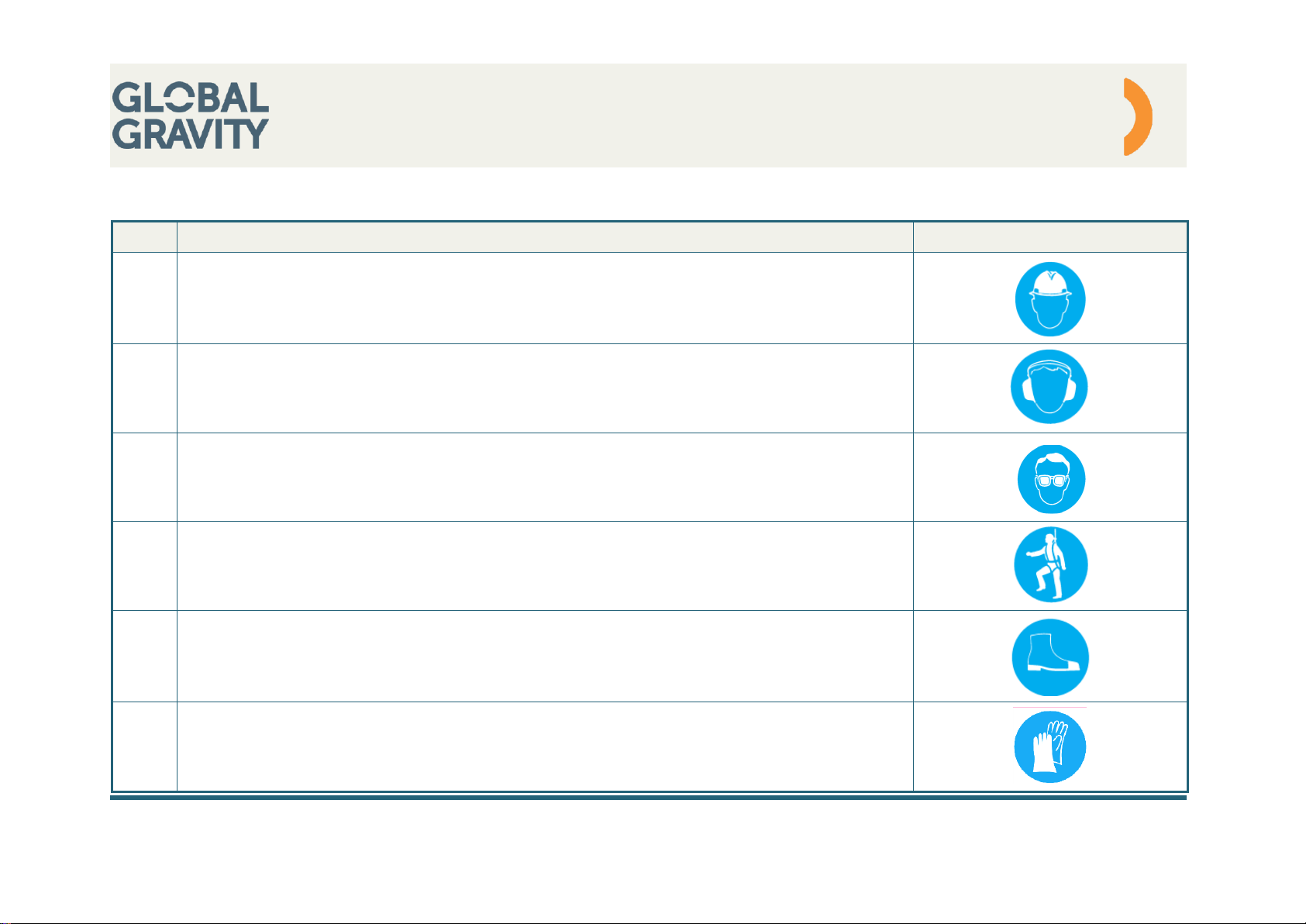
2 Personal protective equipment (recommended by Global Gravity)
Item:
Description:
PPE
01
Safety helmet during crane handling due to:
• Falling objects
• Personal hazards
• Mechanical hazards
02
According to local regulation
03
According to local regulation
04
Fall protection equipment when using TubeLock® in heights due to:
• Fall hazards
05 Safety shoes due to:
• Mechanical hazards
• Falling objects
• Personal hazards
06
Gloves due to:
• Personal hazards
User manual
- 5 -
Global Gravity ApS ● Lillebæltsvej 37 ● DK 6715 Esbjerg N ● CVR: 33950705
Rev. 02
www.globalgravity.dk
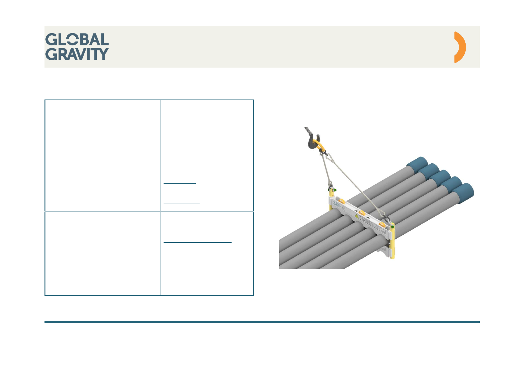
3 System data
Configuration
2⅜ - 14”
Tubing
Range 1-3
SWL
6,0 ton
Load test
2 x SWL
DNV certification
DNVGL-ST-0378
CE marked
Yes
Slings standard
Wire sling:
EN13414-1
Chain sling:
EN 818-4
Lifting poles
System with 3 frames:
3 left + 3 right / package
System with 4 frames:
4 left + 4 right / package
Shackles
Green pin 4,75 ton
Material
Profiles: Aluminum
Poles: Steel
Bolt tensioning (M 20)
150 Nm
User manual
- 6 -
Global Gravity ApS ● Lillebæltsvej 37 ● DK 6715 Esbjerg N ● CVR: 33950705
Rev. 02
www.globalgravity.dk
4 Layout
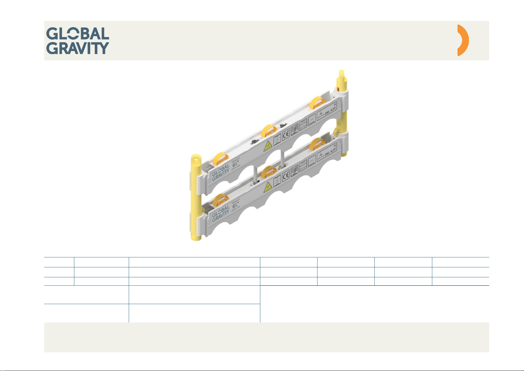
4.1 Package assembly
Standard assembly
Includes 3 sets of profiles
Optional assembly
Includes 4 sets of profiles
User manual
- 7 -
Global Gravity ApS ● Lillebæltsvej 37 ● DK 6715 Esbjerg N ● CVR: 33950705
Rev. 02
www.globalgravity.dk
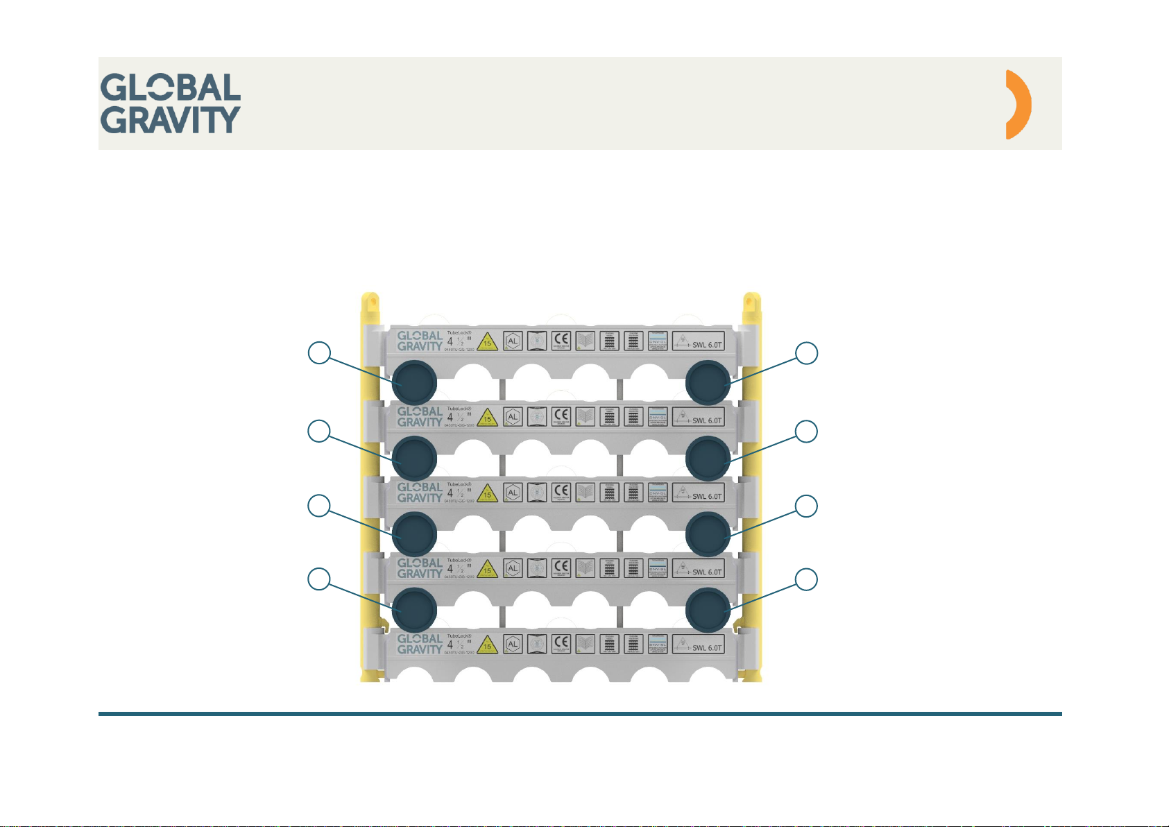
4.2 Packing configuration – Empty spaces
There must always be at least one pipe in each side, per layer, in the position closest to lifting poles. Pipes A & B must be in full length, and go
through all the frames.
Pipe placement is applicable for all sizes and systems.
A
B
A
B
AB A
B
User manual
- 8 -
Global Gravity ApS ● Lillebæltsvej 37 ● DK 6715 Esbjerg N ● CVR: 33950705
Rev. 02
www.globalgravity.dk
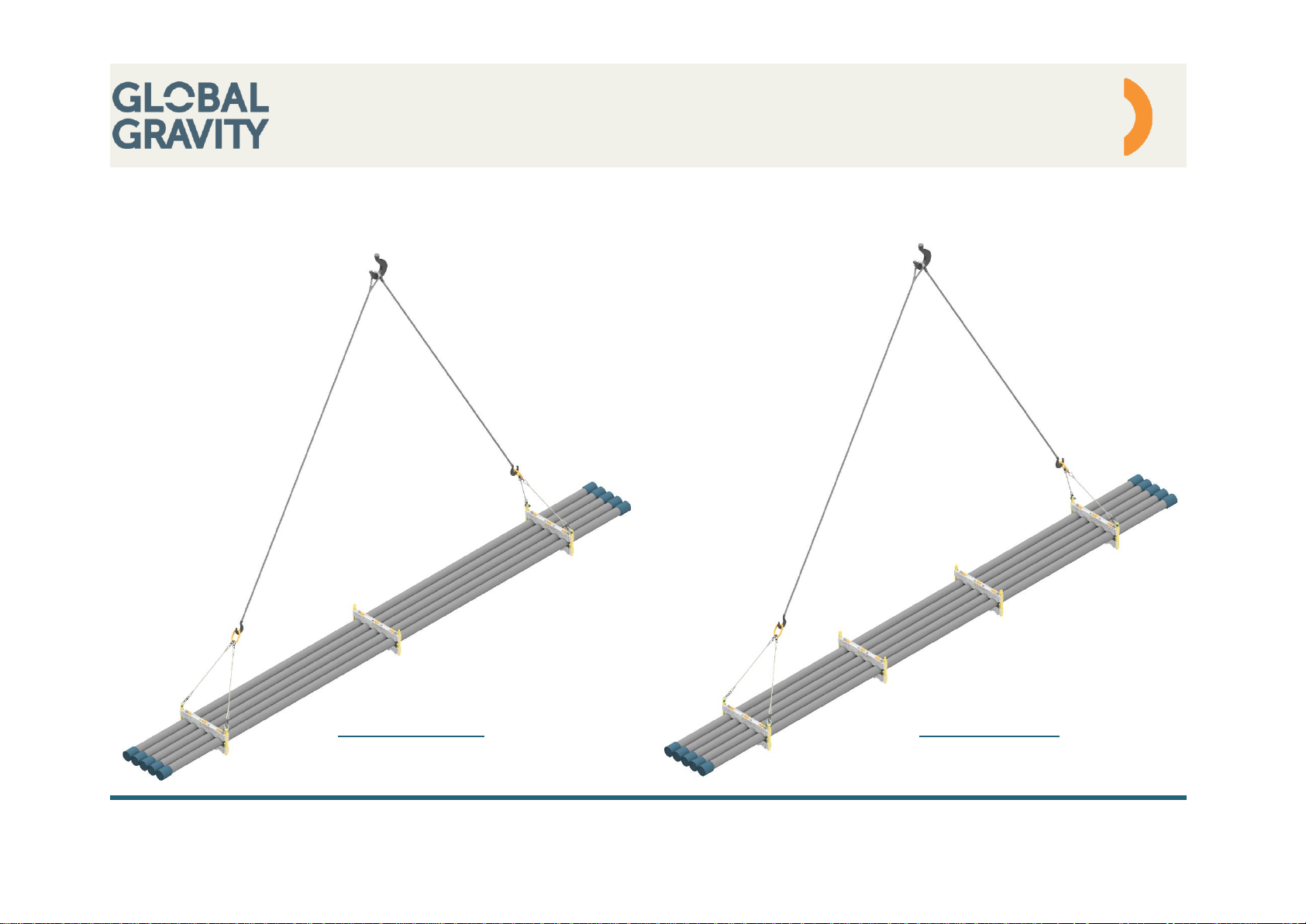
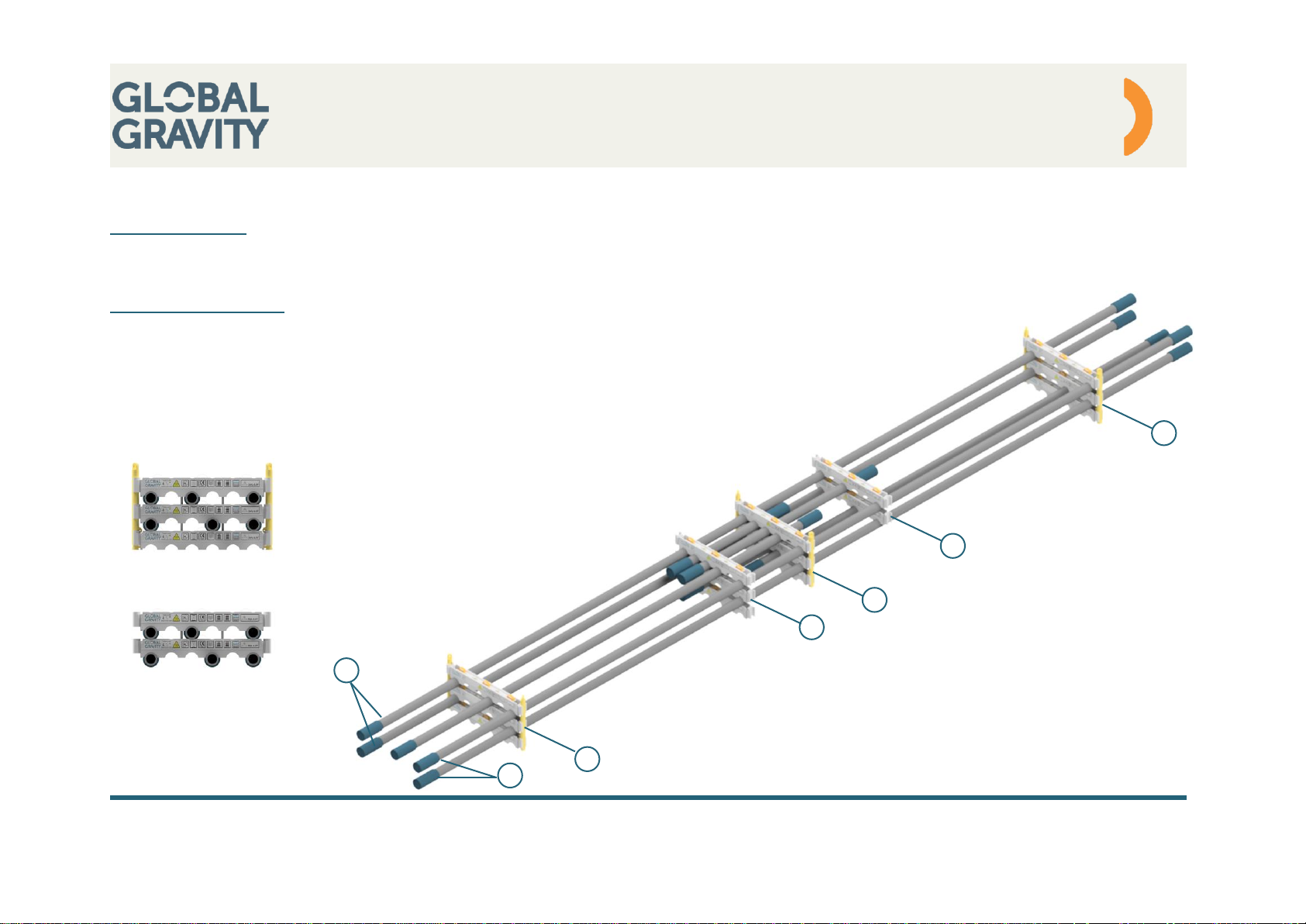
4.3 Packing configuration – Different pipe length
Placement of pipe
Pipe A & B must be full length, and go through all frames. There must be as a minimum, of one pipe in each side per layer, in the position
closest to lifting poles
Securing of short pipes
Extra frames must be placed where it is necessary.
The weight of additional frames and pipes, must be placed even on both sides of centerline.
Lifting poles must be installed in frame assembly 1, but can be avodided in frame assembly 2
For further informations of special configurations, please contact Global Gravity for advise.
A
B
Frame assembly 1
Frame assembly 2
1
122
1
 Loading...