

Global garden products Autoclip 325, Autoclip 145, Autoclip 500, Autoclip 700, Alpina AR2 Technical Manual
...Page 1

1
TTeecchhnniiccaall M
Maannuuaall
LLaaw
wnn
M
Moo
w
weerr
R
Roobboott
TTrroouubblleesshhoooottiinngg
R
Reevviissiioonn 22
Autoclip 140, 145, 125, 127, 325, 500, 700
Alpina AR2 400, 600, 1200
Lizard S1, S14, S2, M4, M440, M480, M485, Q6
Page 2

2
1. Summary
1. Summary ....................................................................................................................................... 2
2. Connections .................................................................................................................................. 3
3. Troubleshooting ............................................................................................................................ 3
3.1.1 Boder signal issues .................................................................................................................... 7
3.1.1.1 General information ................................................................................................................... 7
3.1.1.2 Displayed messages and robot behaviour .................................................................................. 8
3.1.1.3 Causes and resolution ................................................................................................................ 8
3.1.1.4 Border wire impedance – Standard values and measurement ................................................. 11
3.1.1.5 Wire interruption research with interruption finder tool ......................................................... 11
3.1.2 Recharging issues .................................................................................................................... 12
3.1.2.1 Recharge process description .................................................................................................. 12
3.1.2.2 Errors identification ................................................................................................................. 13
3.1.2.3 Batteries nominal voltage level (Lithium) ............................................................................... 16
4. Troubleshooting – Robot model 140,145,S ................................................................................ 17
4.1 Errors identification ............................................................................................................. 17
4.2 Errors resolution .................................................................................................................. 19
Page 3

3
2. Connections
Robots architecture and devices connections are reported in the “Robot architecture” document.
Each device (motherboard, receiver, display, etc…) has a LED that provides indications about the status of
the device.
The device is correctly working if and only if the LED is blinking (50% period ON and 50% period OFF).
Note: Correct blinking of the LED does not guarantee correct functioning of the device for all its functions.
So, correct blinking of the LED is a necessary condition for proper functioning of the device (and therefore
of the robot), but it is not a sufficient condition.
3. Troubleshooting
Note: The new 125, 127, 325 - AR2 400, 600, 1200 model has the same architecture of 500, M, series
machines. Therefore, troubleshooting methods are the same.
Excel file "Error_messages_ENG" provides complete list of error messages and error codes for such robot
models.
Error messages and error codes provide complete description of the occurred fault and / or behavior of the
robot that caused the STOP. The table has to be used as a starting point for troubleshooting.
Tables in the following provide troubleshooting information both for errors that are automatically detected
by the robot and not automatically detected. Description of the errors automatically identified by the robot
and showed on the display is provided in italics format in the table below.
BUS Error
Bus Error is showed in case there is a communication error between the motherboard and
the slave devices. The problem can occur in different modes:
• During normal functioning, the robot shows the message for a few and then it is
removed. The robot continues working well. This is just a warning message. Nothing
has to be done.
• As soon as the robot is turned ON. Check fuse F1. If it is not burned, it is necessary
to disconnect the following devices: motors, receiver, bluetooth, alarm.
o Try to turn robot ON. If the error is still present, the motherboard or the
display are failed.
o Connect one at a time the devices previously disconnected. Try each time to
turn the robot ON and verify if the error is showed.
• As soon as the robot exits the base. When the robot exits the base, it starts the
communication with the display. If the error is showed in this moment, it could be
caused by the flat connecting the motherboard to the display or by a failure in the
motherboard or display.
Out of Border
Probable causes:
- Problems related to correct detection and measurement of the border signal
- The charger (power supply) enter temperature protection mode. In this case, try to
increase the distance between the transmitter and the power supply and install them
in a more fresh and ventilated area
- Slope is too high near the border wire. Solution could be the installation of clawed
wheels; set a lower movement speed for robots with this setting available; increase
the distance between the border wire and the border of the lawn.
Page 4

4
- Bump sensors blocked or not functioning. Check robot functioning after a bump.
Check robot functioning with “No perimeter” setting, raised wheels and verify it does
not drive back as it detected a bump. Verify absence of “Bump error”
- Disturbance to wheel motors. If all the other causes above have been excluded, try to
replace wheel motors.
Low Battery
Reuced working time
with respect to nominal
one
Reduced working time with respect to nominal value can be caused by various causes,
including problems related to the recharging process.
So, verify that the recharging process is performed in the correct way and that the batteries
are in good status (Test Battery). See paragraph Errore. L'origine riferimento non è stata
trovata..
In any case, it is first of all suggested to perform the following verifications:
- On user menu, turn autosetup OFF and verify if the robot works in accordance with
the nominal working time or in accordance with the working schedule set on user
menu
- On user menu, turn rain sensor OFF and verify. In addition, verify that the robot is
not in recharging base with wrong “RAIN” indication
- Clean and sharpen the blade
- Check and clean recharging plates and bolts
- Leave the robot on recharge all the night and verify the first working cycle of the day
- Verify that blade motor speed is correct (test motors or debug during nornmal
functioning)
Robot devices that could decrease working time due to anomalous power consumption are:
- Blade motor
- Blade
When the robot is turned
ON, robot setup (date,
time, working times, …)
is lost
If checksum error is not shwed:
Check backup battery on motherboard: voltage should be about 3.3V. Change battery or the
complete motherboard.
E01 – E02 – E03.
Motor error: right wheel,
left wheel, blade
The display (second line) shows the reason of motor error:
• CURR = Too high current consumption
• RPM = Motor blocked or unable to measure the speed
• WDOG = Communication error
• FAIL = Internal motor error (probable issue on wiring)
Probable causes:
- Failed motor
- Failed encoder
- Damaged brushes
- Driver on motherboard
- Fuse F1 on motherboard
- Grass or mud on blade or blade motor shaft
- Wirings
Use Test motors (service menu) to perform accurate tests.
Use debug to show current consumption on display during normal functioning.
First of all check wirings and fuses.
If the problem is still present, for blade motor try to replace it in order to understand if the
problem is the motor or the motherboard (use Test motors to actuate the motor and verify
motor turns and the speed is correctly showed).
For wheel motors:
1. Disconnect connectors on motherboard of the motor for which the error is showed
and connect in place of the other motor connectors
2. From Test motor menu, actuate wheel motors and verify if the motor identified as
failed is working or not (turning correctly and speed is correctly read)
a. If the motor works, the motherboard is failed
b.
If the motor does not work or speed is not measured, the motor is failed
Page 5
5
The other solution, easier if spare parts are available, is to replace one at a time the
components.
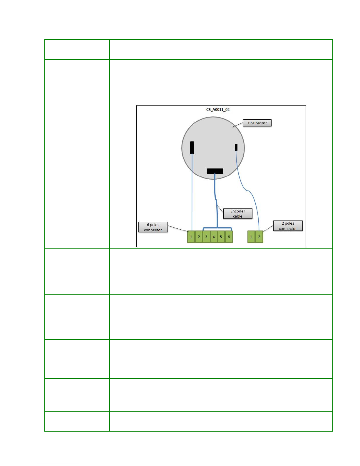
Brushed blade motor
wiring
Pay attention to blade motor wiring.
The correct wiring is showed in the figure below.
Wire color is not important, but only the connections between motor contacts and connectors
are to be considered.
Contacts on motor have different shape, so it is not possible to invert the wiring on the
motor.
Tall grass
- Grass is really tall
- There is some material (grass, mud, etc…) on the blade or blade motor shaft
preventing the motor to correctly turn
- Damaged blade motor bearing
- Damaged blade motor encoder
- Failed motherboard
Bump Error
Robot does not identify
bumps
Probable causes:
- Verify proper positioning and fixing or the cover
- Using service menu, Test bump, verify which is the damaged bump sensor
- Verify that no springs are damaged inside the bump groups
- Verify wirings and connections
- Failed bump board
Safety handle does not
work (blade is not turned
OFF when the handle is
touched)
Verify:
- On user menu, the safety handle feature is enabled
- Turn robot OFF and ON and verify
- Verify handle wiring
- Verify proper measurement values by using Service menu, Safety handle (see “Robot
set-up” document)
Clock Error
Date and time are not
update
Change motherboard
Checksum Error The robot shows this error when the setting parameters stored in the memory are not
correct. Press ENTER when the message is shown. In this way, the robot will ignore the
error and the user can set robot setting (date, time, schedule, etc…).
Page 6

6
If the message is shown each time the robot is turned ON, change the motherboard.
Sync Error Only on robot with sinusoidal signal.
Probable causes:
- Signal receiver is not correctly connected to the motherboard. Connection /
disconnections are to be performed with robot OFF.
- Fuse F1 on motherboard is failed
- Receiver is faulty
- Coating on receiver pins preventing correct contact. Clean pins.
- Damaged coil wiring (coil or connector side). Check connections on connector.
High Battery
In case the robot shows too many errors (more than 3 in a month) it is necessary to check
power supply voltage. In case it is correct, the voltmeter on motherboard is probably failed.
In this case it is necessary to change the motherboard.
Blade turned OFF The robot turns the blade OFF for the following reasons:
• Safety handle activated
• Rain sensor activated
• The robot is raised with inclination higher than 30°
• High blade motor or driver temperature
• Lost border signal
If the robot turns blade OFF and this can not be caused by normal functioning as above
described, check that the sensors causing blade turn OFF (handle, rain, inclinometer,
temperature) work well.
Robot turns OFF after
few seconds it is turned
ON
One of the following components is faulty:
- Batteries
- Motherboard
- Keyboard
- Display
- Flat connecting motherboard to display
The robot automatically
turns ON as soon as the
batteries are connected
The failure is caused by one of the following components:
- Keyboard
- Display
- Flat connecting display to motherboard
- Motherboard
Follow procedure below to identify the failed component:
• Disconnect the batteries
• Disconnect the flat connecting motherboard to display board
• Disconnect the keyboard from the display
• Connect batteries
o If the robot turns ON, the motherboard is faulty
o Otherwise, connect the flat connecting the motherboard to the display. If
the robot turns ON, the display is faulty or the wiring is damaged or there is
condensation on the wiring.
o Finally, if steps above did not replicate the problem. Connect the keyboard
to the display. Robot should turn ON. If yes, replace the keyboard.
It is not possible to turn
robot OFF
One of the following devices is faulty:
- Keyboard
- Display
- Flat connecting display to motherboard
- Motherboard
It is necessary to replace one at a time the devices above listed in order to identify the cause
of the problem.
Page 7

7
3.1.1 Boder signal issues
3.1.1.1 General information
The robot needs to measure the signal generated by the border wire always while working: while it is
working far from the wire, while it is working near to the wire, during wire following while going back to
the base or to secondary areas.
Each time the robot exits the base at the beginning of a new working cycle, it performs the following
procedure to search the signal:
• The robot exits from the base going straight back for about 1 meter
• The robot turns about 90° in clockwise direction (front of the robot goes inside the perimeter)
• The robot synchronizes with the signal
• At the end of successful synchronization, the robot starts the blade and then starts moving.
If the robot is not able to properly measure or recognize the signal, it can have anomalous behaviours and / or
specific error messages showed on the display:
• No signal
• Blackout
• Irregular movements: moving direction inversion, rotations without any reason, moving speed
reduction
• Blade shut-down (not attributable to normal operation or other causes. See details in table above)
• Frequent synchronizations (360° turns)
• Anomalous oscillations right and left with respet to the wire during wire-following.
Signal issues can be cotogorized into 2 main categories, resulting in different robot bahaviours and caused by
different causes:
• Absence, temporaneus or persistent, of border wire signal:
o Caused by malfunctions or protections of signal transmission devices (charger, transmitter,
base, border wire) or missing connections
o Caused by missing main power supply (220Vac – 115Vac)
o Failure to measure the perimeter signal due to faults of robot devices (receiver, coil,
motherboard)
• Interference on signal reception by the robot:
o Signal reception attenuation with respect to nominal levels due to improper installation (too
long wire, too big areas with respect to nominal capability of the robot)
o Disturbed reception of border wire signal caused by disturbance internal or external to the
robot (for example: motors brushes too ware, electrical systems located inside or near to the
installation, presence of iron inside or near to the installation, generating distortions to
magnetic field generated by the border wire).
It is very important to perform, during installation and post-installation verifications, verifications to properly
understand if the complete system and installation allow proper working of the robot or not (see the
document “Installation” for suggested verifications to be performed).
If, at the end of installation, it is evident that the robot is able to properly work in all the areas, it will be clear
that if problems will occur later in the future, they will be caused by alterations to the status of the
installation and components. Otherwise, if nothing has been verified at the end of installation, if problems
will arise, it will be first of all necessary to loose time trying to understand if the issuea can be caused by the
correctness of the installation and only after this it will be possible to verify specific devices malfunctions.
Page 8

8
3.1.1.2 Displayed messages and robot behaviour
There are two messages that could be displayed on the display of the robot in case on signal issues. They are
No signal and Blackout.
Robot behavior in case of signal issues varies on the basis of the setup of the Blackout parameter on service
menu:
• STOP: as soon as the robot looses the border wire signal, it stops showing one of the following
messages:
o BLACKOUT SIG04: if it lost the signal during normal functioning (while mowing)
o BLACKOUT SIG02: if it lost the signl during wire-following.
The rebot will not restart moving if the signal will come back ON.
• RESTART:
o If the robot looses the signal during normal functioning (while mowing), it stops with
message No Signal.
If the signal comes back ON, the robot synchronizes with the signal by performing a 360°
turn and:
If it is able to turn 360° without finding a bump or the border wire, restarts working
If it finds a bump or the wire during the 360° turn, it stops with BLACKOUT SIG03
message
o If it looses the signal during wire-following, it stops with BLACKOUT SIG02 message.
What above described can be easily understood in case of real absence, temporaneus or persistent, of the
border wire signal.
It could be much more difficult to understand robot bahaviour in case of disturbances or attenuations of the
signal due to which the signal, that is present, if not correctly measured by the receiver on the robot.
In this case the robot, prior to show messages on the display (that is prior to completely loose signal
measurement), the robot will start to execute some manoveurs in order to establish again proper
measurement, both in case of Blackout paramente on service menu setup to STOP or RESTART.
Tipical manoveurs are, for example:
• Movement speed reduction
• Moving direction invertion
• Partial rotation.
Signal related issue can result, both in case of Blackout paramenter on service menu setup to STOP and
RESTART, on only anomalous working, without messages showed on the display.
3.1.1.3 Causes and resolution
In order to understand, verify and solve all the issues in a complete and analytic way, it is suggested to
collect all the information of the following list:
• robot model
• software version
• statistic menu, robot report (blackout)
• lawn dimension (square meter)
• border wire length
• is 48V amplifier present? (only for sinusoidal signal)
• border wire impedance (ohm)
• transmitter part-number and dip-switch setting
• transmitter LED status
• receiver part number and reception channel (dip-switch setting for TX-S1 signal, value on label for
sinusoidal signal)
• charger and transmitter location
• locations on the lawn where the problem occurs, with distance from border wire:
o does the problem occur always in the same location?
Page 9

9
o does the problem occur near to a flowerbed?
o How many times does the problem occur? Every time the robot goes near to the same
location?
o Is there iron or electricity systems or cables (fence, electrical cable active or not active,
sidewalk, wall, etc…) near to the location where the problem occurs?
Rebember that, on statistic menu, submenu Blackout, there are 3 values related to blackout events. The third
number indicates how many times the robot stopped since last time statistics were cleared.
As stated on “Robot set-up” document, it is suggested to clear statistics (generate a report robot before) each
time the installation or robot is modified to solve signal issues. Only in this way it will be possible to clearly
understand the goodness of the implemented modifications.
Possible cause Verifications and suggestions to solve the issue
Charger: failed or heat protection
condition
Verify the 29.3V voltage is present between pins 1 and 2 on cirvular
connector
Verify the transmitter is ON (LED is ON)
Try to turn charger OFF and turn it ON again after at least 15
minutes and verify
In case of frequent failures or frequent charger heat protection
function activation, modify installation of the charger and
transmitter (increase distance between charger and transmitter. It
has to ba considered that, for sinusoidal signal, the transmitter is the
biggest heat source)
Transmitter: failed or internal fuse
failed
Verify LED status
Verify internal fuse status
Border wire interrupted (both
electrical conductors and
insulation), oxidized, not well
insulated with respect to ground,
with bad joints
Check LED on transmitter to verify indication of interrupted wire or
too high impedance on wire
Perform border wire impedance measurement and comparison with
nominal values. In case of need, perform interruption research by
using the interruption detector tool (see next paragraph).
Perform a wire to ground insulation measurement (see next
paragraph).
Recharging base cabling for border
wire interrupted, damaged or
oxidized
If transmitter is not embedded on recharging base: measure total
impedance of border wire and recharging base cabling. Measure on
the two central pins of female connector normally connected to the
transmitter.
If transmitter is embedded on recharging base: all the cabling are
inside the transmitter box. So, try replacing the transmitter.
Coil inside the robot is
disconnected or cabling is damaged
Visually verify the status of coil wiring on both sides. Check
connector.
Check that the wiring is located on the proper position.
Try to replace the coil.
Failed receiver If present, verify the status of the LED on the receiver: it should
blink regularly.
Try to replace the receiver.
Receiver pins do not have good
contact with motherboard
connector
Remove the receiver, clean the pins and connect again to
motherboard
The coil inside the robot is not in
the proper position
Perform a visual check and in case of need put the coil in the proper
position
Transmitter and receiver are set on
different channels
Verify setup of transmitter and receiver
Page 10

10
Sinusoidal transmitter set with too
low transmission power
Verify dip-switch setup on transmitter. Transmission power shall be
at 100% (if there are not other near installation or other systems
receiving disturbance from the signal on the wire)
In case of installation with two
robots, two recharging bases, but
only one transmitter: transmitter set
to shut signal transmission down
when the robot is inside the base
Verify dip-switch configuration on transmitter
Flowerbeds are delimited with wire
installed in clockwise direction
If possible, verify wire path at the entrance of the flowerbed.
Flowerbeds installed in the wronf way generally casuse: the robot
identify the wire about 30 cm before the real position; the robot
shows an anomalous behavior near to the flowerbed. The dimension
of the area where the robot shows an anomalous behavior depends
on the dimension of the flowerbed: big flowerbeds generate
distorctions of the magnetic field in far areas from the flowerbed.
Too long border wire and / or
missing 48V amplifier, only for
sinusoidal signal. See technical
tables for border wire length
specification.
Verify that border wire length is lower than maximum admissible
value and 48V amplifier (sinusoidal signal only) is used if necessary
Charger/transmitter/recharging base
not installed in accordance to
requirements described in the
“Installation” document
Verify that installation meets all requirements
Iron or electrical cables (active or
not active) are located inside the
perimeter or near to it
Try to move the border wire far from those zones
If the robot shows problems during wirefollowing, try to set “on
bounce” return
Source of disturbance (electrical
gate, electrical systems, etc…)
located near to the area where the
problem occurrs
Try to move the border wire far from those zones
Other near installations Verify that all requirements related to installation of close
perimeters are met (channel selections and distance)
Try to turn OFF perimeters near to the disturbed one and verify for
proper functioning. In this solve the issues, try to reduce
transmission power and / or increase distance between installations
Note: if there are problems in specific areas located far from the border wire for which the attenuation of the
signal caused by the long distance from the wire is the cause of robot malfunctions (other caused have been
already excluded), it could be useful to increase signal power by the addition of virtual flowerbeds in the
interested areas.
Page 11

11
3.1.1.4 Border wire impedance – Standard values and measurement
Border wire impedance standard correct values are provided in the following table on the basis of border
wire length. Different values are indicative of wire damaging, oxidizing, partial or complete interruption.
Wire length Standard impedance
200m 2.8ohm
400m 5.6ohm
600m 8.4ohm
• The transmitter has to be OFF while measuring wire impedance (turn charger OFF)
• In order to check border wire only: disconnect the wire from the two black and red connectors on
recharging base and measure between the two ends (it is suggested to do not touch with the hands
both the probes of the multimeter and the two ends of the wire)
• If the transmitter is not embedded inside the recharging base: in order to check the total impedance
of border wire and recharging base wiring, disconnect the white connector on transmitter and
measure between the two central pins on plug female connector
• In order to check proper wire to ground insulation: put one probe in the ground and the other one in
contact with both ends of the border wire (disconnected from black and red connectors). Verify that
the measured ohm value is higher than 850Kohm. After this, leave the perimeter wire connected to
the red and black connectors on recharging base and leave the transmitter connected. Add a piece of
wire between the two black and red connectors. If the measured value is lower than 850kohm, it
means that there are wrong made joints or the wire lost proper insulation.
Note: there is not a simple measurement that allows to verify if the transmitter is properly working or not.
Therefore, it is necessary to check the status of the LED on the transmitter.
If the impedance of the wire is too high or the insulation to ground is too low, it could be helpful to use a tool
that allows to identify wire interruption or damaging position. See next paragraph.
3.1.1.5 Wire interruption research with interruption finder tool
The wire interruption finder tool allows the identification of the wire interruption point. The works with
sinusoidal signal Channel A or TX-S1 signal. For better functioning, use of snusoidal signal Channel A is
recommnended for test purposes.
So, if different signals are used (sinusoidal channel B or C), it is necessary to change the set-up on the
transmitter, configured on Channel “A”.
After first turn ON, the tool could remain ON also if it is far from the border wire. In this case, leave the
push button and push it again.
Operation:
• Remove the robot from recharging station.
• Set transmitter to 100% transmission power
• Disconnect the border wire from the black connector on recharging base
• Turn battery charger ON
• Start wire interruption research as described here below:
o Tool antenna shall be located very close to the wire (1cm)
o Follow the wire in anticlockwise direction (starting from still connected end on the back side
of the recharging base: robot entering side)
Page 12

12
o Push the push button on the tool to verify if the border wire is interrupted in that point
o Bring the wire over ground if it is underground to perform the verification. This has to be
performed approximately every 10m.
o If the tool turns ON, the signal arrives in that point. So, the border wire is not damaged till
that point
o If the tool does not turn ON, the interruption is in the section between that point and the last
functioning one
o
In order to be sure about the readings, repeat the verification in the two last points.
ATTENTION!!!! In case the tool emits the sound (turns ON) along the complete perimeter, the wire is
not completely interrupted. In this case, connect to ground the end side of the border wire previously
disconnected from black connector on recharging base. Repeat research.
Once the interruption has been found, connect correctly the border wire to the connectors on recharging
station and repair the border wire where it is damaged. As suggestion, use 3M Scotch 23.
3.1.2 Recharging issues
3.1.2.1 Recharge process description
Battery recharge process is as described in the following:
Note: the battery charger (power supply) always provides power to the recharging plates. When the robot is
not inside the base, the voltage shall be at its nominal value of about 29.3V.
1. The robot, following the wire, arrives near to the base, measuring the voltage at the recharging bolts
by using the voltmeter embedded inside the motherboard (the relay embedded in the motherboard
that connects together the recharging bolts and the battery has still open contacts)
2. When the robot enters the base and the recharging bolts on robot touch the recharging plates on base,
the voltmeter on robot measures the voltage of the recharging plates and understand it has reached
the recharging position. So it stops.
3. The relay embedded inside the motherboard connects the recharging bolts to the battery and the
recharging process starts. The plot in the following shows a typical trend of voltage on battery and
recharging current
4. At the end of recharging process (when the recharging current goes below a certain threshold), the
relay opens the contacts and the recharging bolts are no more connected to the battery
5. The robot is now ready to start a new working cycle.
Page 13

13
Blue: voltage measured by voltmeter embedded in motherboard
Purple: recharging current
Voltage and current trends during recharge are highly dependent on battery conditions.
Considering that the batteries are at their best conditions and all the elements involved in recharging process
are perfectly functioning, the trend is highly dependent on charge status of the battery at the beginning of the
reachrging process.
As it is evident looking at the plot above, that is related to a condition with discharged batteries at the
beginning of recharge:
• the recharging current is high at the beginning of the process and decreases over the time. It goes
more or less to 0A at the end of recharge
• voltage on battery (and at recharging plates) assumes values significantly lower than nominal one
(29.3V) at the beginning of the process and then it increases. The voltage reaches the nominal value
at the end of recharging process.
The trends above are different in case the old battery charger (black box instead the new power supply with
white box) is used. In this case, the current is more or less constant during the complete recharging period
and the voltage increased reaching the nominal value at the end.
3.1.2.2 Errors identification
Typical errors and anomalous behaviours showed by the robot in case of the recharging process is not
optimized, are:
• Failed charge: this error is showed in the display of the robot
o Failed charge errors are counted in the statistics of the robot, are visible on service menu and
are reported on robot report
o As explained in “Robot set-up” document, the statistics do not count as errors missed
recharging due to bump of the robot against the recharging base or recharging plates
o Only errors for which the recharging process effectively started (contact established between
recharging plates and bolts) and then ended erroneously are counted
• The robot enters the base and immediately exits
• The robot is inside the base and shows “PAUSE” instead of the normal ON RECHARGE message
• Anomalous working and recharging times
Page 14

14
In addition, it has to be remembered that the statistics menu (and robot report) shows the parameter LAST
CHARGE TIME that provides the length of the last recharging process.
This parameter is updated only if the robot entered the base bacouse of low battery. So, in case the robot
entered the base and the end of a working cycle ended for other reasons rathen than low battery, the value is
set to 0.
In order to verify that the recharge process is correct and all the items involved in the process are functioning
well (power supply, transmitter, recharging base, robo recharging circuit, batteries), it is possible to verify
the following:
• the recharging time (that depends on robot model and type of batteries installed) is in accordance
with the nominal value provided in the “Robot set-up” document. Both times lower or higher than
nominal value are erroneous.
• Voltage between pins 1 and 2 of the power supply circular connector (disconnect the connected
device) is 29.3V (+/- 0.1V)
• voltage at recharging plates, without robot inside the base, is 29.3V (+/- 0.1V)
• at the beginning of the recharge process the recharge current assumes a value in accordance with the
power supply on use:
o higher than 1.5A for 2.3A power supply
o higher than 4A for 5A power supply
o higher than 7A for 8A power supply
• during the whole recharging process the voltage measured at the following measure points is more or
less the same (consider 1V tolerance):
o between the two recharging plates on recharging base
o between the two recharging bolts on power supply
o between + and – poles of bump groups recharging connectors
o between + and – poles of recharging circuit on motherboard
o between + and – poles of betteries connectors on motherboard
o between + and – poles of batteries
• voltage measured by the voltmeter embedded inside the motherboard and showed on robot display is
congruent with the value measured on batteries by using a multimeter
• recharging plates and recharging bolts are clean and do not show signs of oxidation (if necessary,
clean by using sandpaper).
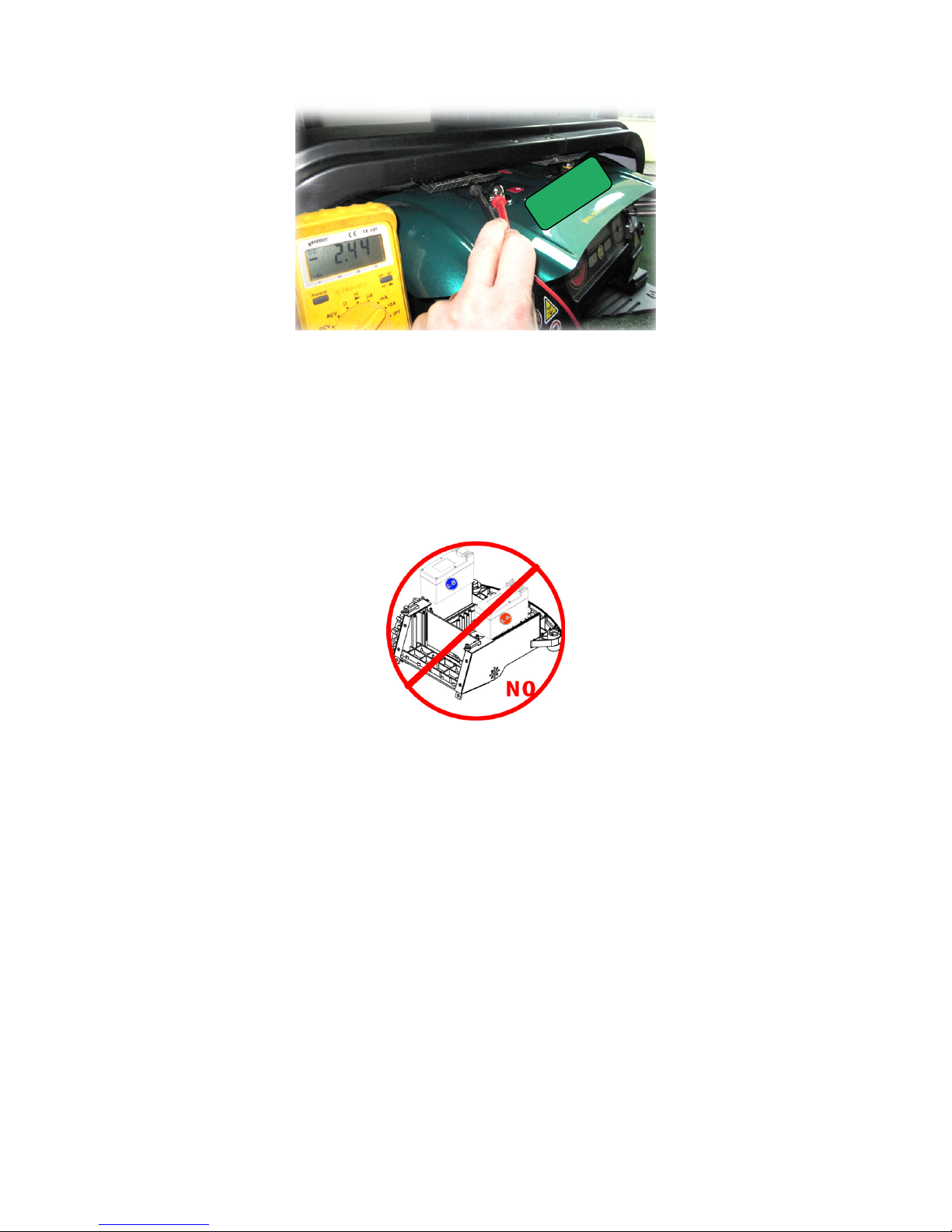
If it is necessary to measure the recharging current, follow the procedure provide here below:
1. Locate the robot inside the recharging base so only one recharging bolt is in touch with the related
recharging plate
2. Set the multimeter for current measure, with proper scale
3. On the other side, put the probe of the multimeter in touch with the recharging bolt and the other
probe in touch with the recharging plate
4. Perform the measurement, paying attention that the recharging bolt does not touch the plate
Page 15
15
In addition, check:
• No steps are at the entrance of the recharging base
• The border wire is correctly installed under and near the base (see “Installation” document: it is
straight, located in the middle of the base
• All the wiring and connectors of power supply, transmitter, recharging base, recharging plates do not
show signs of axidation, burns, insulation damage
• Springs on recharging plates provide a good contact between recharging plates and bolts
• Robot is provided with same battery type (A or B) and the correct type is set on service menu
• In case the robot has more than one battery, check robot function with only one battery at a time and
verify that:
o The recharging process is in accordance to the description above
o The robot works well (obviously, with reduced working time)
• In order to verify the status of the batteries, perform the battery test as explained in the “Software
update” document.
For robot models that do not allow to remove the cover and measure both the voltage at recharging bolts and
plates and in points internal to the robot, it is possible to use the winter recharge adapter connecting it
directly to the recharging bolts of the robot.
Finally, if all the verifications above suggested did not allow to identify the cause of the issue, it is necessary
to change one at a time all the following items and verify the goodness of the recharging process each time:
• Power supply
• Rechaging base (wiring and plates)
• Recharging wiring part of bump groups on robot
• Recharging wiring on robot
• Motherboard
• Batteries
Page 16
16
3.1.2.3 Batteries nominal voltage level (Lithium)
Reference voltage levels are provided in the following table:
Lithium A Lithium B
Robot turn OFF value
22 22
Blade turn OFF value
23.5 24.8
Begin of recharge research
value
24 25.2
Charge value
29.3 29.3
Maximum allowed value at
the end of recharging
process
29.9 29.9
Page 17
17
4. Troubleshooting – Robot model 140,145,S
4.1 Errors identification
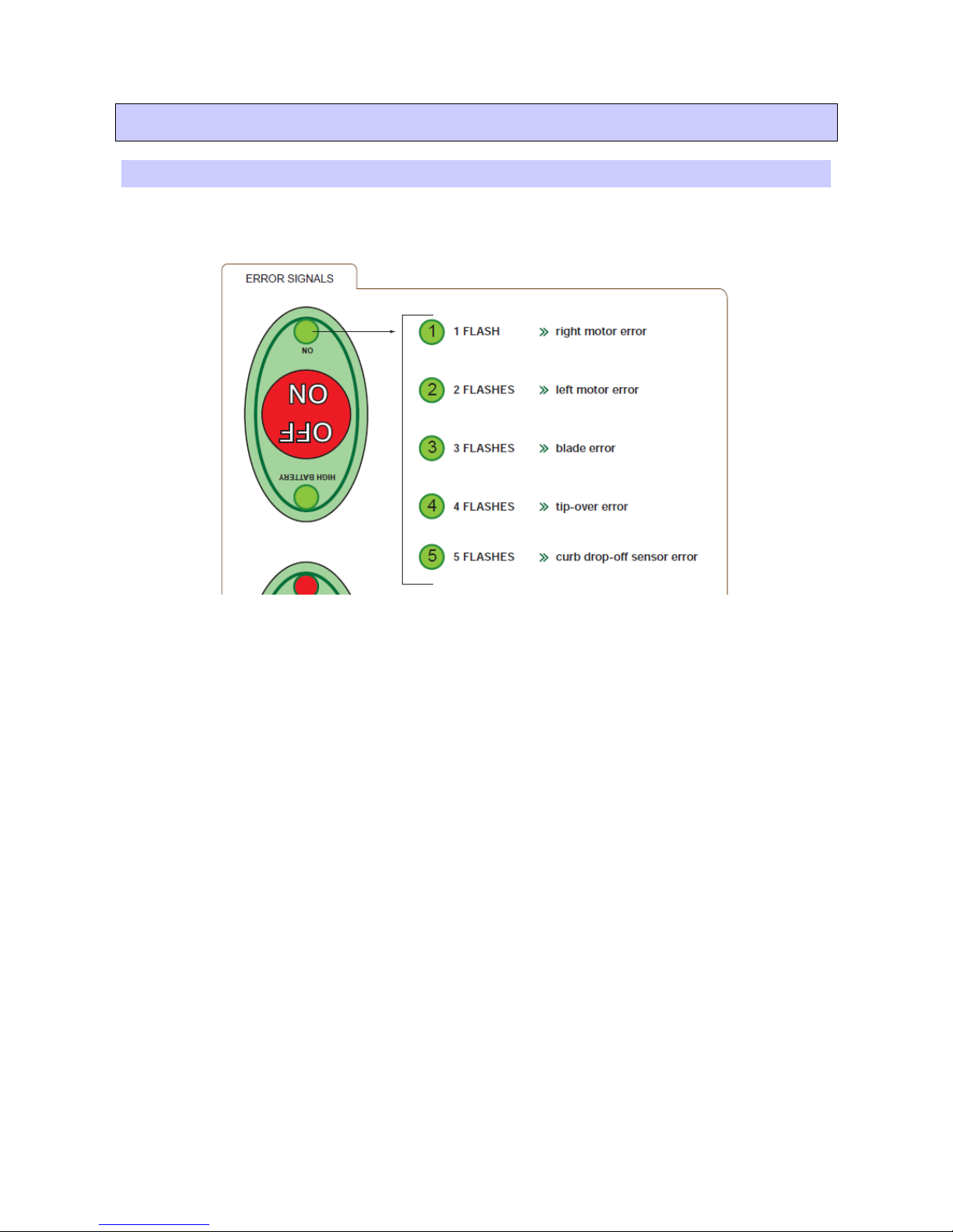
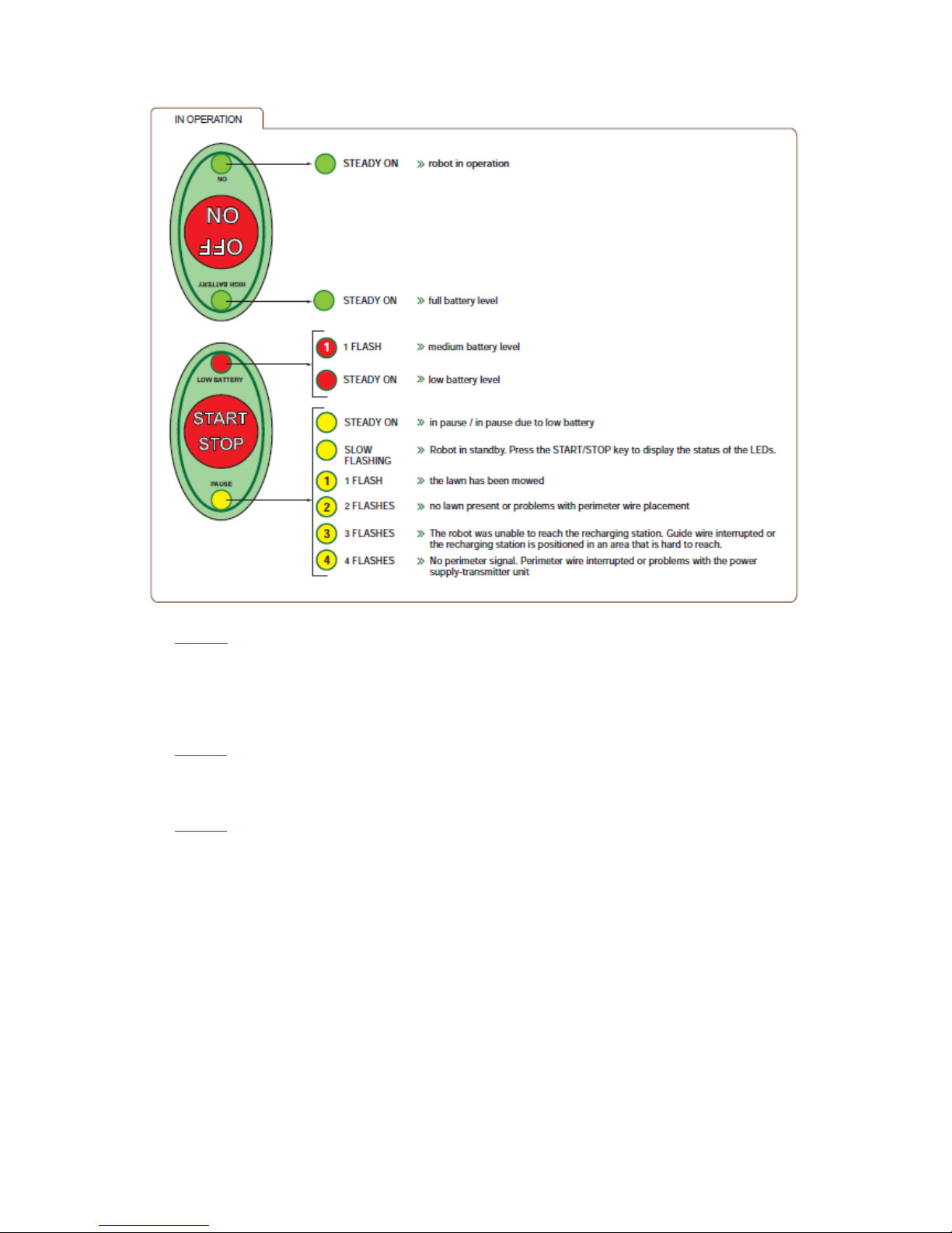
In case there are failures on robot components, the ON LED blinks to show the cause of the failure, as
explained in the figure below.
In case the PAUSE LED is blinking slowly (Robot in stand-by), push the START/STOP key in order to exit
stand-by, enter PAUSE and so visualize the status of the ON LED and identify the error.
ATTENTION!!! : If, when the robot is turned ON, the ON and PAUSE LEDs blink alternately, the robot test
has not been performed by using the Stiga – Lizard Client. Perform the test as described within the “Software
update” document. The same indication (test not performed) can be obtained by performing the autodetection
procedure (robot software update) of the software installed. In this case, the Test B is NOT showed as
“Pass”.
Other possible anomalous conditions are showed by the robot by using the PAUSE LED, according to the
following figure.
Page 18
18
• 2 blinks: the robot stopped for safety reasons since it didn’t find grass for al long period of time (if
working without border wire) or because it detected to be out of border without any reason (if
working with border wire). It is suggested to verify the goodness of the indication and, in case,
modify the area where the robot showed the problem if necessary. If the robot is used with border
wire, please verify that all the distances provided in the “Installation” document are respected,
exscpecially in case of installation on slopes.
• 3 blinks: (only robot with recharging station, installation with guide wire) the robot, bouncing on the
external border of the lawn looking for the guide wire, was not able to reach the wire on time. It is
suggested to verify that guide wire installation is in accordance to all the requirements and
suggestions provided within “Installation” document.
• 4 blinks: (only robot provided with recharging base, installation with border wire) the robot does not
receive the signal from the border wire. Verify the status of border wire (interruptions, oxidations,
etc…), signal transmitter, power supply and all wirings. Verify the compatibility between transmitter
and receiver, verify whole installation is in accordance with imposed requirements.
Page 19

19
4.2 Errors resolution
Robot does not identify border wire
Robot does not enter the base
Robot is turned OFF
Robot shows with LEDs signal problems
- Verify that the robot is not installed over the specification (lawn
dimension, maximum border wire length, etc…)
- Verify compatibility between receiver, transmitter, software
update
- Perform verification on installation and robot in accordance with
all the suggestions above reported for robot of L200 series
Robot often changes movement direction
without any reason, turns blade OFF, stops
indicating tilt error (4 blinks led ON)
Reason
- Motherboard with failed inclinometer
- Damaged blade causing high vibration
Solution and verification
- Perform L50 test and verify inclinometer works correctly
- Try the robot without blade motor
During normal functioning the robot
changes movement direction without any
reason (does not detect grass / detects dropoff)
Reason
- Water
- Damaged / missing connections
- Failed motherboard
Solution and verification
- Clean sensors connectors
- Verify sensors wiring
- Verify for water absence
- Verify motors brushes are not worn
The problem has not been solved? Try to change the following devices
- Motherboard
-
Motors brushes, motors
During test, the test shows:
- High Frequency
- Low Frequency
- Frequency not stable
Reason
- There are magnetic / electric fields providing disturbance during
test execution (border signal, neon, electrical systems, etc…)
- Sensors have been touched at the beginning of the test
- Water on sensors
- Failed motherboard
Solution and verification
- Turn any border signal OFF
- Raise the robot from ground and locate over a table (possibly not
made of steel)
- Locate the robot far from electrical systems
- Do not touch sensors if not required by the test
- Verify for water absence
The problem has not been solved? Try to change the following devices
-
Motherboard
While working:
- The robot recognises late when
there is no grass
- The robot recognises the presence
of a slope late
Most cases depend on the bad interpretation of the robot working
Situations where this behaviour is to be considered as normal:
- Too wet grass
- While turning and changing direction, the sensors sensibility is
reduced
- Undercover of the robot too dirty or wet
Reasons
- Water inside the robot and in the boxes of the grass sensors.
-
Not well isolated sensor support. While assembling the curb drop-
Page 20

20
off sensors, it is necessary to put some silicon to isolate the contact
between the springs.
Solutions and Checks
- Check the robot working in a not too wet garden and its cover is
cleaned.
- Blow air compressed to the protection sponges of the sensors in
order to check.
- By using a tester device check there is no continuity between the
two curb drop-off springs.
- Blow air compressed to the protection sponges of the sensors in
order to check there is no water.
- Check the grass sensors have not detached from their home.
The robot does not turn on.
Reasons
- Internal fuses are burnt
- Problems connected to the ON key
- Batteries are completely flat
Solutions and checks
- Connect the robot to the recharger for a few minutes
- Check the inside fuses
- Check the charging level of the battery
- Disconnect the battery, reconnect it and try again. Reset the
board.
- Open the robot and assemble the body in reverse with the ON key
positioned in the Start connector. (For safety purposes, run the
test without the blade). Obviously, the controls will be inverted but
this operation allows understanding if the key is broken or if the
board is broken.
Has the problem not been solved? (Spare parts to check)
- Motherboard
- Keyboard
- Battery
- Cabling
The robot turns on but the Start key does
not work and the robot does not start.
Reasons
- Keyboard is defective
- Robot is charging
- Motherboard is broken
Solutions and checks
- If connected, disconnect the robot from the recharger
- Disconnect the battery, reconnect it and try again. Reset the
board.
- Press the “Start” key is pressed, the sound of a disconnecting or
connecting relay should be heard. If this sound is heard, it is likely
that the motherboard thinks it is being recharged and therefore
the robot does not start.
- An additional check for understanding if the problem relates to
the motherboard or to the keyboard involves opening the robot,
assembling the body in reverse with the ON key positioned in the
Start connector. (For safety purposes, run the test without the
blade). If the robot turns on when the "Start" key is pressed, this
means that the key is working
Has the problem not been solved? (Spare parts to check)
- Motherboard
- Keyboard
Page 21

21
The robot always stays on. Reasons
- Keyboard is defective
- Robot is charging
- Motherboard is broken
Solutions and checks
- If connected, disconnect the robot from the recharger
- Disconnect the battery, reconnect it and try again. Reset the
board.
- An additional check for understanding if the problem relates to
the motherboard or to the keyboard, involves opening the robot,
assembling the body in reverse with the ON key positioned in the
Start connector. (For safety purposes, run the test without the
blade). If the robot turns on and off when the “Start” key is
pressed, then this means that the key is working and the failure
should be in the motherboard.
Has the problem not been solved? (Spare parts to check)
- Motherboard
- Keyboard
The robot occasionally pauses for no
reason (low batteries, lawn moved, no grass
or error)
Reasons
- Keyboard is defective
- Handles came into contact with wet objects
Solutions and checks
- Try the robot with another body and then with different
Start/Pause keys.
- Run (only temporarily) the robot with the cables of the handles
disconnected from the motherboard. Of course, this test reduces
the safety of the product. It is not a solution but only a test.
The robot occasionally turns off and when
it restarts the batteries are not low.
Reasons
- Keyboard is defective
- Battery
Solutions and checks
- Try the robot with another body and then with different
Start/Pause keys.
- If the problem depends on the battery, the test is not simple. The
robot can be started if the blade is blocked, but this is not a simple
test to execute. The safest procedure is to try the robot with a fully
charged battery.
Blade motor frequently turns off
This does not necessarily mean that there is something wrong with the
robot.
Normal reasons.
- Slope is greater than 30° or slope of 20° is reached too quickly.
- Grass is too tall, too much strain on the motor
- A handle was touched.
- No grass or zone with grass lower than the 6 sensors
- Cutting blade damaged that creates strong vibrations to the
mother board.
Reasons due to defective or worn parts.
- Blade motor encoder
-
Motor cutting brushes worn
Page 22

22
- Motherboard with faulty handle sensitivity.
Solutions and checks
- Start the robot normally. If the modulation functions correctly,
this should mean that the encoder is functioning.
- Open the robot; disconnect the cabling of the handles. Retry the
robot without this functionality (if the problem is resolved contact
GGP)
- Try the robot without the cutting disc. (If the problem is solved,
the fault could be in the cutting motor, in the worn out brush or in
the damaged blade that creates strong vibrations).
Has the problem not been solved? (Spare parts to check)
- Motor cutting brushes
- Motor cutting encoder
- Cutting motor
- Motherboard.
- Cutting disc.
The robot does not turn correctly after
doing a U-turn and makes too many turns,
which affect the normal functioning of the
robot.
NB. The robot cannot control the direction
and therefore it is normal that it continues
to turn.
Reasons
- Loose belt
- Wheel motor with worn brushes
- Wheel motor with problems
Solutions and checks
- Check the tightening of the belt. If loose, tighten the screws of the
motor and of the free block by applying a medium Loctite
adhesive
- Check the brushes of the wheel motor
- After allowing the robot to operate, open the body and check the
temperature of the wheel motors which must be the same. If a
motor is a lot hotter, this means that it is under too much strain.
Has the problem not been solved? (Spare parts to check)
- Wheel motor
- Mechanical part
- Motherboard
The motherboard has been disassembled or
the wheel motors have been disassembled
and afterwards the robot does not detect
that there is no grass until the back sensors
exit from the border.
Reasons
- The cables or connections of the wheel motor were inverted
Solutions and checks
- Check that the connections on the board and wheel motor are
correct. (The red cable must be facing upwards) as shown in the
figure.
-
Page 23

23
To check the correct functioning it is necessary to turn on the robot and
press the “Start” key. The first movement is executed in the direction
opposite to the recharging knobs. As indicated by the arrow in the figure.
Problems with reduced operating times
Obviously, the first evaluation that must be made is based on the life of
the battery. In case of a new or recent battery, carry out the following
checks:
- On the Battery there must be the label “Li-Type A” or “Li-Type
B” with a version come out later than “2009-04-16”
- Clean the blade and grass residuals
- Clean and check the recharging knobs as well as the impedance of
the recharging knobs as showed in the picture
- Recharge the robot all night long and check the first operating
cycle.
- Recharge the robot all night long. Disconnect the recharging
knobs and measure the voltage with a tester on the knobs of the
wheels. The voltage must be approximately 29.1-29.4Volt
- Measure the recharging connectors when they are disconnected
from the wheel knobs. The voltage must be approximately 29.2-
29.4Volt
The fault may be in:
- Power Supply Unit
- Battery
- Recharging cable
- Motherboard
- Cutting motor
-
Blade
Page 24

24
Wheel motor error. One or two flashes of
the “ON” LED
The fault may be in:
- motor
- Worn brushes
- Cable on the wheel motor
- Motherboard
- Blocked belt
- Objects blocking its movement
Blade motor error. Three flashes of the
“ON” LED
The fault may be in:
- Hitting of a rock
- Burnt motor
- Encoder
- Worn brushes (replace the brushes)
- Motherboard
- Motor wires broken or disconnected due to vibrations of the
BLADE. As for the motors manufactured before W25/09 we must
check the pin as indicated in the picture
Blade motor wiring Pay attention to blade motor wiring.
The correct wiring is showed in the figure below.
Wire color is not important, but only the connections between motor
contacts and connectors are to be considered.
Contacts on motor have different shape, so it is not possible to invert the
wiring on the motor.
 Loading...