

Page 1

Karara
DECORATIVE FUEL EFFECT GAS FIRE
Installation, Maintenance & User Instructions
Hand these instructions to the user
Model No’s GSRC**MN, GSRP**MN & GSRD**MN are for use on
Natural Gas (G20) at a supply pressure of 20 mbar in G.B. / I.E.
** denotes trim & fret variant
Page 2

CONTENTS
Section 1 Information and Requirements PAGE
1.0 Appliance Information 3
1.1 Conditions of Installation 4
1.2 Flue and chimney suitability 4
1
.3 Fireplace / surround suitability 5
1.4 Shelf position 5
1
.5 Chimney inspection 5
1.6 Fire place opening / catchment space 6-7
1
.7 Fitting to Chair bricks 8
1
.8 Precast Flues 8
1.9 Metal Flue boxes 8
1.10 Hearths 9
1.11 Spillage Monitoring System 9
Section 2 Installation of Fire
2.1 Unpacking the fire 10
2.2 Installing the fire box 10-16
2.3 Gas tightness and burner pressure 16-17
Section 3 Assembling Fuel Bed and Commissioning
3.1 Assembling the ceramics and fuel bed (Coal models) 17-19
3.2 Assembling the ceramics and fuelbed (Pebble models) 19-21
3.3 Assembling the ceramics and fuelbed (Driftwood models) 21-26
3.4 Fitting the Trim 27
3.5 Fitting the Fret 27
3.6 Lighting the appliance 28
3.7 Checking for clearance of combustion 28-29
products
Section 4 Maintenance
4.1 Removal of the Burner Assembly 30
4.2 Removal of the Piezo Igniter 30
4.3 Removal of the Control Tap 31
4.4 Removal of the Thermocouple 31
Section 5 User Instructions Section
5.1 Conditions of Installation / About Your New Gas Fire 32-33
5.2 Operating the Fire 34
5.3 Assembling the Coal Fuelbed 35-36
5.4 Assembling the Pebble Fuelbed 37-38
5.5 Assembling the Driftwood Fuelbed 39-44
5.6 Cleaning the Fire 45
This appliance is manufactured by :-
CFM Europe Ltd.
Trentham Lakes,
Stoke-on-Trent,
ST4 4TJ
2
Page 3

SECTION 1
INFORMATION AND REQUIREMENTS
1.0 APPLIANCE INFORMATION
Model GSRC**MN, GSRP**MN & GSRD**MN
Gas Type G20
Main injector (1 off) Size 440
Burner Type Aeromatic Self Vitiating Tubular Burner
Max. Gross Heat Input : 6.5 kW
Min. Gross Heat Input &
Ignition Rate : 2.2 kW
Cold Pressure : 20.0 +/-1.0 mbar
Ignition : Push-button Piezo
Electrode Spark Gap 4.0mm
Packed Weight (All Models without fret) 9.0 kg
Packed Weight (All models with fret) 12.5 kg
Packed Weight (All models with Contemporary Trim) 10.5 kg
Fire box Dimensions (with trim fitted)
Width : (with trim fitted) 473mm
Height : (with trim fitted) 595mm
Depth : (from mounting face to rear panel) 120mm
Gas Connection : 8mm Compression (Supplied with fire)
3
Page 4

INSTALLATION REQUIREMENTS
1.1 CONDITIONS OF INSTALLATION
It is the law that all gas appliances are installed only by a GAS SAFE Registered
Installer, in accordance with these installation instructions and the Gas Safety
(Installation and Use) Regulations 1998 as amended. Failure to install appliances
correctly could lead to prosecution. It is in your own interest and that of safety to
comply with the law.
The installation must also be in accordance with all relevant parts of the Local and
National Building Regulations where appropriate, the Building Regulations
(Scotland Consolidation) issued by the Scottish Development Department, and all
applicable requirements of the following British Standard Code of Practice.
1. B.S. 5871 Part 3 Installation of Decorative Fuel Effect Gas Fires
2. B.S. 6891 Installation of Gas Pipework
3. B.S. 5440 Parts 1 & 2 Installation of Flues and Ventilation
4. B.S. 1251 Open fire place components
5. B.S. 715 Metal flue pipes for gas appliances
6. B.S. 6461 Part 1 Installation of Chimneys and flues
7. B.S. E.N. 1858 Chinmeys Components & Concrete Flue Blocks
8. I.S. 813 : 1996 Domestic Gas Installation (Republic of Ireland)
No purpose made additional ventilation is normally required for this
appliance, when installed in G.B. When Installing in I.E. please consult
document I.S. 813 : 1996 Domestic Gas Installation, which is issued by the
National Standards Authority of Ireland. If installing in Northern Ireland,
please consult local building regulations. Any purpose made ventilation
must be checked periodically to ensure that it is free from obstruction.
1.2 FLUE AND CHIMNEY SUITABILITY
This appliance is designed for use with conventional brick built or lined chimneys
and fabricated flues. It is also suitable for use with pre-cast flue blocks conforming
to B.S. E.N. 1858 and metal flue boxes conforming to BS 715. All flues must
conform to the following minimum dimensions.
Minimum diameter of circular flues 125 mm (Without Flue
Restrictor Fitted)
Minimum effective height of all flue types 3 metres
When fitting to conventional chimneys or 175mm flues it may be desirable to
leave the flue restrictor baffle (supplied) in place to reduce the flue flow and
increase the efficiency of the fire. Safe clearance of products must
always
be checked by carrying out a smoke match test as described.
4
Page 5

1.3 FIREPLACE / SURROUND SUITABILITY
The fire must only be installed on a hearth it must not be installed directly onto
carpet or other combustible floor materials.
The fire is suitable for fitting to non-combustible fire place surrounds and propri-
etary fire place surrounds with a temperature rating of at least 150oc.
If a heating appliance is fitted directly against a wall without the use of a fire
surround or fire place all combustible material must be removed from behind
the trim. Soft wall coverings such as blown vinyl, wall paper etc. could be
affected by the rising hot air and scorching and/or discoloration may result.
Due consideration should be made to this when installing or decorating.
1.4 SHELF POSITION
The fire may be fitted below a combustible shelf providing there is a minimum
distance of 200mm above the top of the fire and the shelf does not project more
than 150mm. If the shelf overhangs more than 150mm the distance between the
fire and the shelf must be increased by 15mm for every 25mm of additional
overhang over 150mm.
1.5 FLUE / CHIMNEY INSPECTION
Before commencing installation, a flue or chimney should be inspected to ensure
that all the following conditions are satisfied.
1. Check that the chimney / flue only serves one fire place and is clear of any
obstruction. Any dampers or register plates must be removed or locked in
the open position.
2. Brick/stone built chimneys or any chimney or flue which has been used for
an appliance burning fuel other than gas must be thoroughly swept. The
base of the chimney / flue must also be thoroughly cleared of debris etc.
3. Any under-floor air supply to the fire place must be completely sealed off.
4. Ensure that the inside of the chimney / flue is in good condition along it’s
length and check that there is no leakage of smoke through the structure
of the chimney during and after the smoke pellet test. With pre-cast flues
it is especially important to check the inside of the flue for extruded
cement / sealant protruding from the joints between the flue
blocks. If present, these should be removed by rodding the flue
before proceeding with the installation.
5. Using a smoke pellet, check that there is an up-draught in the
chimney / flue and that the smoke can be seen issuing from the
terminal / chimney pot outside.
5
Page 6
There must be no leakage of smoke through the structure of
the chimney during or after the smoke pellet test and it is
important to check inside upstairs rooms adjacent to the chimney /
flue. Check the chimney pot / terminal and general condition of the
brickwork or masonry. If the chimney or flue is in poor condition or if
there is no up-draught do not proceed with the installation. If there is a
history of down-draught conditions with the chimney / flue, a tested and
certificated flue terminal or cowl suitable for the relevant flue type should
be considered.
6. A spillage test must always be carried out during commissioning of
the appliance.
1.6 FIRE PLACE OPENING AND CHIMNEY CATCHMENT SPACE
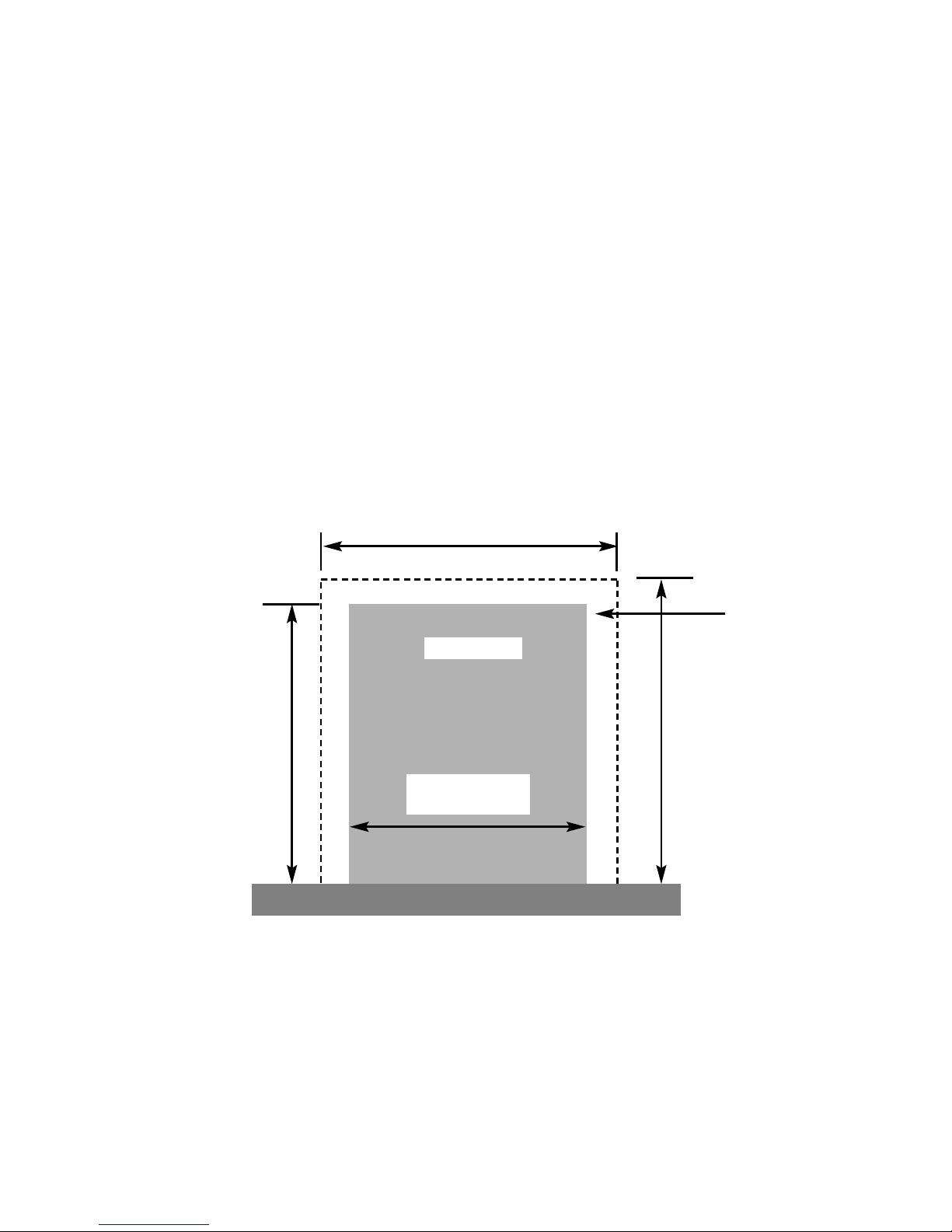
The front opening of the fire place must be between 330 and 440 mm wide, and
between 550 and 575mm high. If the opening exceeds these dimensions then a
surround must be constructed from suitable non-combustible material to produce a
correct size opening. Any surround must be suitably sealed to the fire place to
prevent leakage. See below in fig.1
When installing into a brick built chimney, you must ensure that there is sufficient
depth to accomodate any debris which may fall from the chimney. This depth
must be sufficient to accomodate 12 litres of volumetric space.
Fire Opening
330mm Minimum
440mm Maximum
600mm
Minimum
355mm Minimum
Fig. 1
550mm Minimum
575mm Maximum
Minimum Flat
Sealing Area
6
Page 7
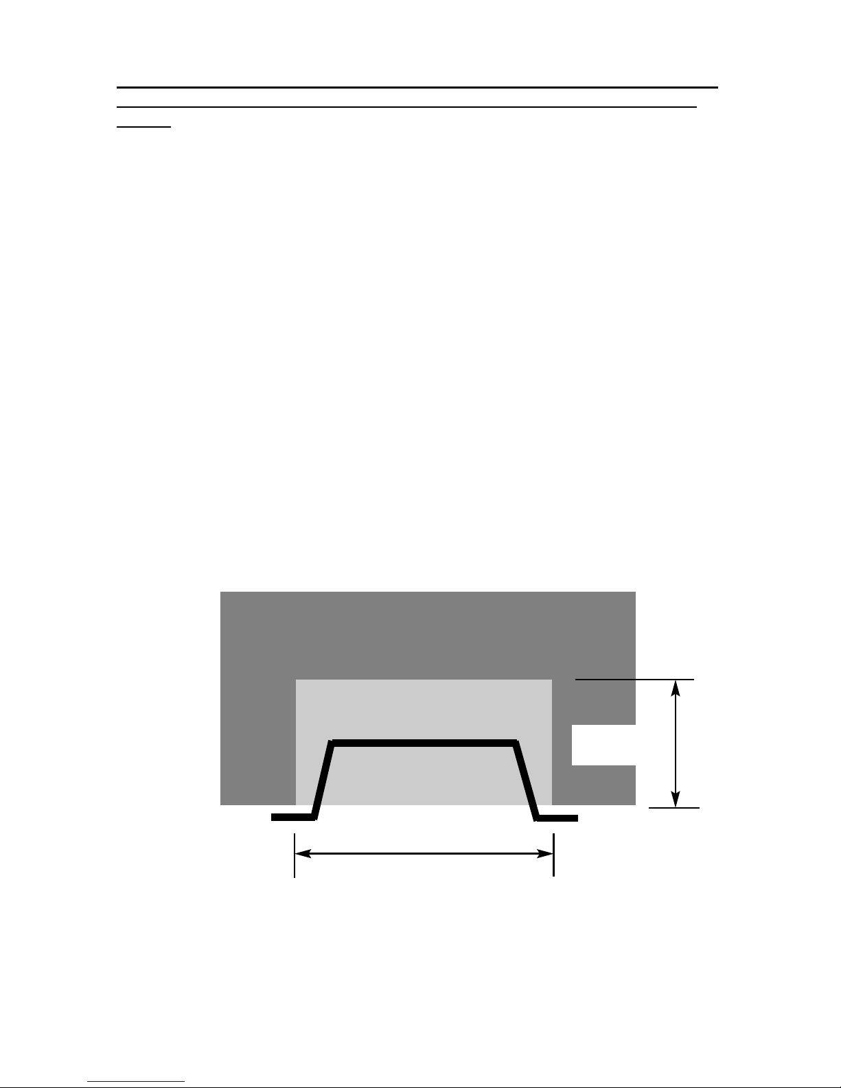
Table A - Installation Depth Requirements for a Global Karara being installed
into a brick built chimney, requiring 12.0 litres of debris collection volume
(fig. 2).
Opening Width (mm) Minimum Depth Required (mm)
330 (minimum opening width) 152
340 149
350 146
360 144
370 142
380 139
390 137
400 135
410 132
420 130
430 127
440 (maximum opening width) 125
For example, if the appliance was to be fitted into a 400mm wide opening, the
depth required would be 135mm. See fig. 2 below for explanatory diagram.
Fig. 2
7
Opening Width ( e.g. 400mm)
Depth Required
(e.g. 135mm)
Page 8

1.7 FITTING TO FIREPLACES WITH EXISTING CHAIRBRICKS AND
CONVENTIONAL BRICKBUILT CHIMNEYS
This appliance is suitable for use in fireplaces fitted with an existing chairbrick
without the need for removal of the chairbrick, providing the minimum depth of the
fireplace exceeds 175mm. If the depth is less than 175mm then the chairbrick
must be removed. The fireplace must be checked to ensure that no part of the
chairbrick is within 50mm of the flue outlet of the fire when installed.
1.8 FITTING TO PRE-CAST FLUE INSTALLATIONS
When installing this appliance into pre-cast flues, always ensure that the
spigot restrictor baffle has been removed. This is held in place on the spigot
by 2 screws
To install the fire box in to pre-cast flue starter blocks, there must be at least
125mm from the mounting face of the fire to the rear of the pre-cast flue
starter block to allow sufficient space for debris collection. If this dimension is
less than 125mm then a fire surround with a deeper rebate to increase the depth
to at least 125mm from the mounting face of the fire. It is important to consider
this depth when choosing a fire surround as the thickness of the fire surround
must be sufficient to give a total depth of at least 125 mm to the rear of the
starter block, otherwise there will be insufficient depth. To increase this depth the
fire surround may be packed away from the wall using suitable non-combustible
board, providing the installation is correctly sealed. If in doubt about the suitability
of the fire contact BFM Europe Ltd. for advice before proceeding.
It is important to ensure that the pre-cast flue is in good condition and is free from
extruded mortar or sealant from between the flue blocks.
This appliance has been tested for use in a pre-cast flue block complying
with BS EN 1858. In accordance with BS EN 1858, pre-cast flues built with
directly plastered faces (front or rear) are not correctly installed as to ensure
proper operation with any type of gas fire. In some instances of this flue
construction, temperature cracking of surface plaster may occur through no
fault of the appliance. An air gap or some form of insulation material should
be installed to prevent normal flue temperatures from damaging wall
surfaces.
1.9 FITTING TO PRE-FABRICATED TWIN WALL METAL FLUE BOXES
The appliance may be fitted to twin wall metal flue boxes conforming to the constructional requirements of BS 715, (for example the Selkirk LFE 125 box). The
box must have a minimum flue diameter of 125mm internal and minimum internal
dimensions of 160mm deep by 580mm high by 350mm wide. There are no
maximum dimensional requirements for the box. The top face of the box must be
insulated with a minimum thickness of 50mm of non-combustible mineral wool
insulation or similar material. The flue box must stand on a non-combustible base
of minimum thickness 12mm.
8
Page 9

1.10 HEARTHS
This appliance must only be installed on to a concrete or non-combustible hearth.
The hearth material must be a minimum thickness of 12mm with the top surface at
least 50mm above the floor. The hearth must be fitted symmetrically about the fire
opening and have a minimum width of 760mm and a minimum projection of
300mm forwards from the fire opening.
1.11 SPILLAGE MONITORING SYSTEM
This appliance is fitted with an atmosphere sensing spillage monitoring system in
the form of an oxygen sensing burner. This is designed to shut the fire off in the
event of a partial or complete blockage of the flue causing a build up of combustion products in the room in which the fire is operated. The following are
important warnings relating to this spillage monitoring system :-
1) The spillage monitoring system must not be adjusted by the installer.
2) The spillage monitoring system must not be put out of operation.
3) When the spillage monitoring system is exchanged only a complete original
manufacturers part may be fitted.
9
Page 10

SECTION 2
INSTALLATION OF FIRE
2.1 UNPACKING THE FIRE
Carefully lift the fire out of the carton. Remove the loose item packaging carefully
from the front of the appliance. Check the contents as listed :-
Packing Check List - Coal Fuelbed Models
1off Fire box / burner assembly
1off Boxed ceramic base and 7 synthetic coals
1off Loose items bag.
1off Brass, Black or Chrome Effect Trim (3 piece on models supplied without
a fret, 1 piece on all other models)
1off Boxed Fret & Ashpan cover (dependent upon model selected, some
models are supplied without a fret)
1off each Installation / User book (Combined)
Packing Check List - Pebble & Driftwood Fuelbed Models
1off Fire box / burner assembly
1off Boxed ceramic base and 7 synthetic pebbles (4 large, 3 small) or
7 driftwood pieces
1off Loose items bag.
1off Contemporary Trim & Ashpan Cover
1off each Installation / User book (Combined)
2.2 INSTALLING THE FIRE BOX
Establish which type of flue you are intending to install the fire in to :-
225 x 225mm (9 inch x 9 inch) brick built chimneys
175mm (7 inch) diameter lined brick or stone flue, or insulated pre-fabricated
metal flue box to B.S. 715.
When installing into 125mm (5 inch) diameter lined brick or stone flue, or
insulated pre-fabricated metal flue box to B.S. 715 and pre-cast flues the
restrictor baffle must not be fitted.
A spillage test must always be carried out to check satisfactory
clearance of flue products, regardless of the type of flue the
appliance is being fitted to.
10
Page 11
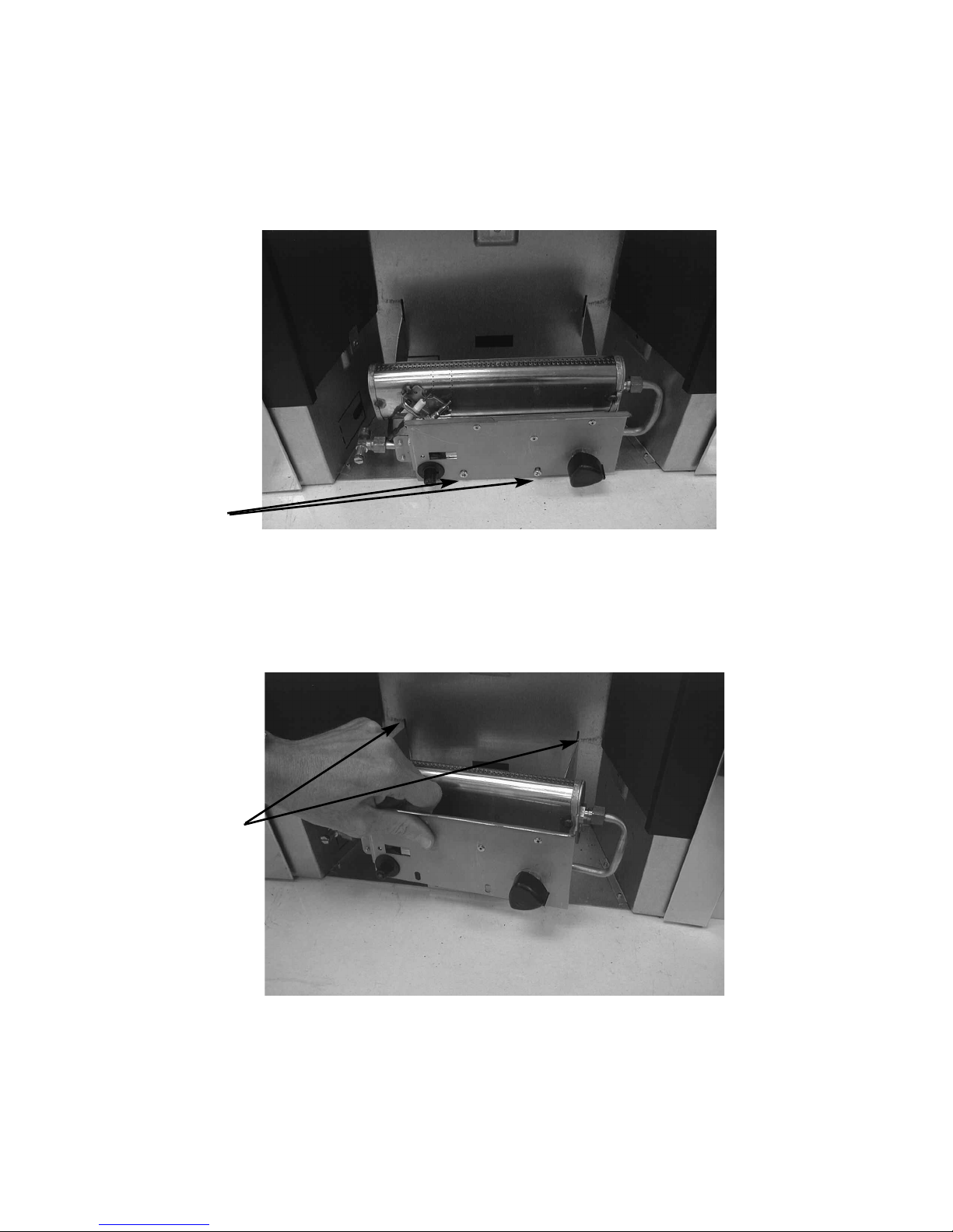
Proceed as follows :-
a) Remove the two screws at the bottom of the control panel. See fig. 3
below
Fig. 3
b) The base of the burner unit can now be lifted, lift the two retaining
tabs on the burner brackets from the back of the firebox, allowing
the burner to be removed. See fig. 4 below
Fig. 4
c) Ensure that the hearth is protected from damage and carefully lift the
fire box into the fire opening, then slide it back into position. Check that
the fire box flange fits flush to the sealing face of the fire surround or
wall with no gaps present.
11
2 burner
retaining
screws
Retaining
Tabs on
burner
Page 12
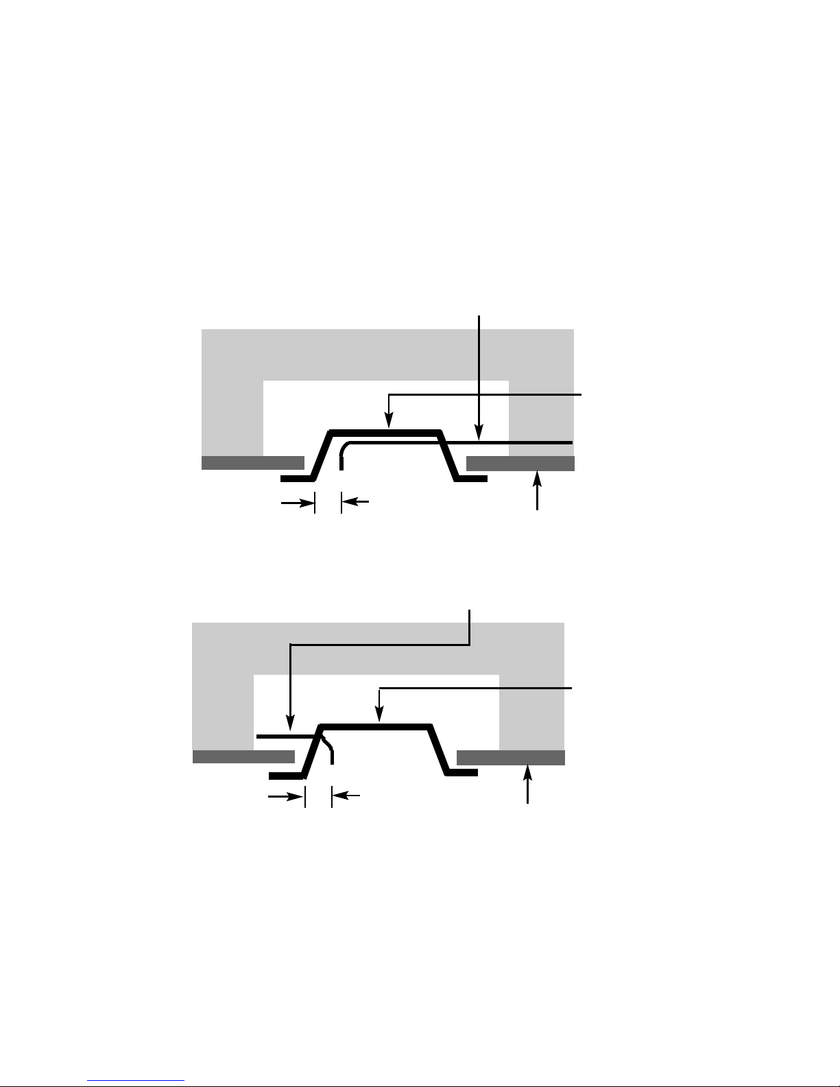
d) Whilst the fire box is still in position, decide which side the gas supply is
to enter the fire from. If concealed pipe work is required plan the pipe
run to enter the fire box through one of the openings in the sides or rear
of the fire box below the fuelbed support panel and connect to the
isolating / inlet elbow. The gas connection to the appliance should be
made to the isolating / inlet elbow using 8mm rigid tubing. There must
be no soldered joints within the firebox. See fig. 5a & 5b below for
suggested concealed pipe layouts.
Fig. 5a
Fig. 5b
Note : Before breaking into the gas supply a pressure drop test should be
carried out to establish that the existing pipework is sound.
Carefully withdraw the fire box from the opening to enable the gas supply and fire
fixing to be completed.
12
Firebox
Approx.
40mm
Fireplace
Gas Supply
Firebox
Approx.
40mm
Fireplace
Gas Supply
Page 13
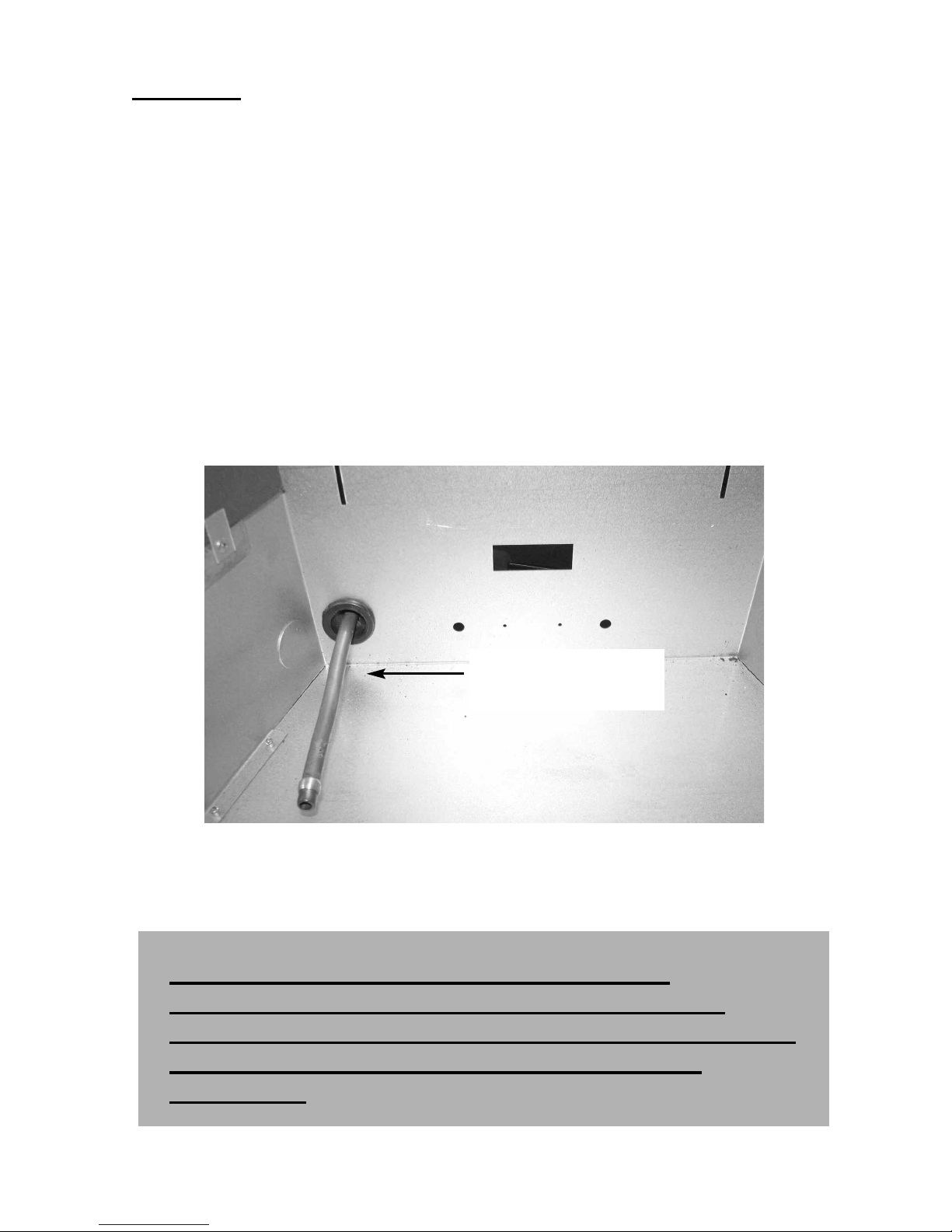
IMPORTANT : Sealing of the Gas Inlet Apertures
In line with current GAS SAFE regulations, it is imperative that the gas supply
inlet aperture that is utilised during the installation is sealed with the
grommet as supplied in the loose items pack. The product is manufactured
with 3 knock out gas inlets in the firebox wrap to allow a left hand, right hand or
rear gas inlet supply to the inlet elbow. Using a hammer and a blunt chisel,
remove the inlet aperture selected and then seal with the grommet supplied. To
provide access for the gas supply pipe, cut the grommet with a sharp knife.
Failure to seal the inlet apertures could lead to flame reversal, which in turn will
damage the burner and control systems of the product.
Fig. 6 below shows a correctly sealed installation.
Fig. 6
PLEASE NOTE :-
BFM EUROPE WILL NOT BE LIABLE FOR
GUARANTEE CLAIMS THAT ARE AS A DIRECT
RESULT OF THE GAS INLET APERTURE NOT BEING
CORRECTLY SEALED WITH THE GROMMET
PROVIDED.
Grommet fitted and cut to
provide access for the gas
supply pipe.
13
Page 14
There is a choice of methods of fixing the firebox which are provided to enable the
installer to deal with any type of installation.
The preferred method of fixing which is suitable for almost all situations is
the cable fixing method which is described in the following section in detail.
The fire may be secured using the cable method as described below, or
alternatively, in installations where the cable method is not suitable (eg. loose
masonary in rear of fire opening) the fire box can be directly secured to the fire
surround using the screws and rawlplugs provided.
To fit using the preferred cable method proceed as follows-
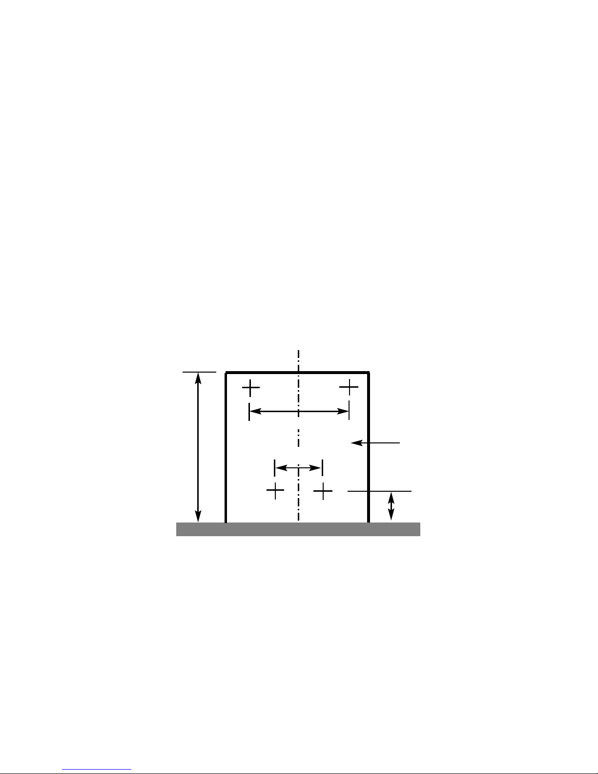
e) Mark out and drill 4 off No 14 (7mm) holes in the back face of the fire
opening in the positions shown below in fig. 7
Fig. 7
Fit the wallplugs provided and screw the fixing eyes securely into the rear of the
fire opening. If the clearance at the rear of the fire is at the minimum specified for
a precast flue application, it may be necessary to bend over the lower fixing eyes
after screwing them fully in to the rear of a pre-cast starter block.
f) Uncoil the two fire fixing cables and thread one end of each of the
cables through one of the two holes on each side of the flue outlet
shroud.
14
Fireplace Opening
325mm
100mm
500mm
20mm
Page 15
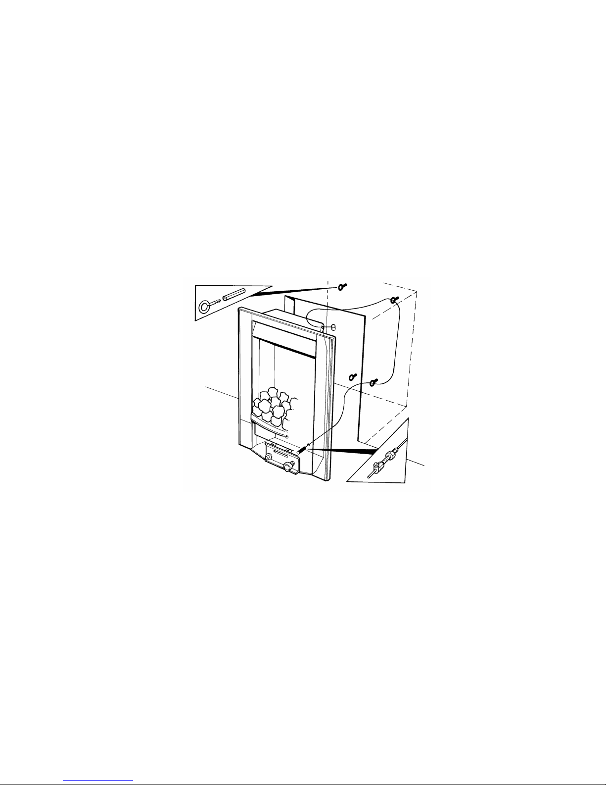
g) Position the fire carefully on the (protected) surface of the hearth and
reach into the fire opening. Thread each of the cables vertically
downwards through the pair of fixing eyes on the same side of the fire.
Thread the free end of the cables through the corresponding circular
hole on each side of the lower rear of the fire. Carefully slide the fire
box back into the fire opening and pull both cables tight.
h) Thread a tensioning screw over each of the cables and ensure that the
tensioning nut is screwed fully up against the hexagon shoulder of the
tensioning screw (this provides maximum travel for the tensioning nut).
i) Fit a screwed nipple on to each of the cables and pull hand tight up
against the tensioning screw, then secure each nipple with a flat
bladed screwdriver. See fig. 8 below
Fig. 8
j) Evenly tighten the tensioning nuts to tension both cables and pull the
fire snugly against the wall. Do not overtighten, it is only necessary to
pull the seal up against the sealing face of the wall, it does not need to
be compressed. Check that there are no gaps behind the seal.
k) With the fire securely in place, if a concealed gas connection has been
made through either of the access holes in the sides or rear of the fire,
the holes should be closed around the pipe to prevent leakage of air
through the gap around the pipe.
l) Refit the burner. Fit the two retaining screws and check that the burner
is correctly locked into position.
15
Page 16
m) Before making the final gas connection, thoroughly purge the gas
supply pipework to remove all foreign matter, otherwise serious
damage may be caused to the gas control valve on the fire.
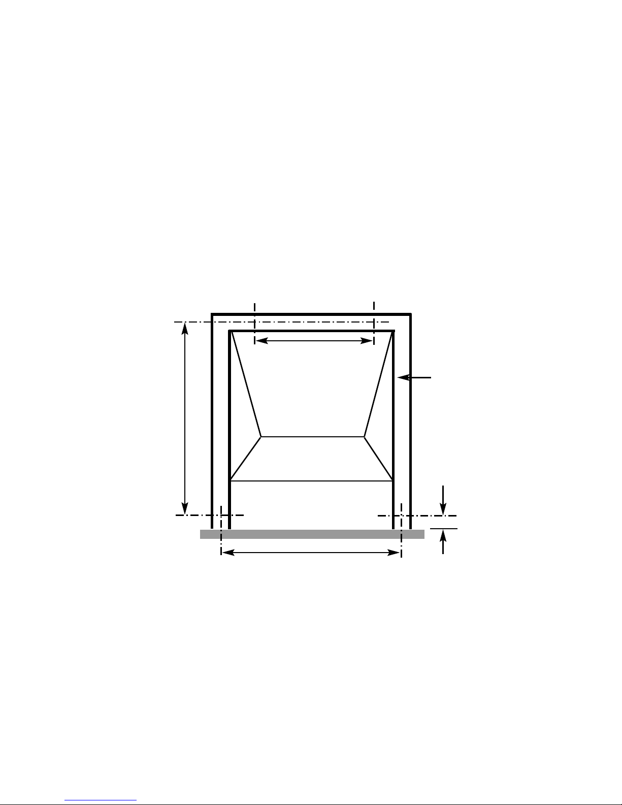
The other firebox fixing method is as follows :-
In installations where the cable method is not suitable (e.g. loose masonary in rear
of fire opening) the firebox can be secured to the fire surround using four screws
and wall plugs provided. Below (fig.9) is a diagram to indicate the hole centre
positions available on the firebox to facilitate the screw fixing to the fireplace /
surround.
Fig. 9
2.3 GAS TIGHTNESS AND INLET PRESSURE
a) Remove the pressure test point screw from the inlet elbow and fit a
manometer.
b) Turn on the main gas supply and carry out a gas tightness test.
c) Depress the control knob and turn anti-clockwise to the position marked
ignition / low. Hold in the control knob for a few seconds to purge the
pipe work then press the igniter button. The burner should light,
300mm
140mm
520mm
430mm
Firebox
Mounting
Flange
16
Page 17
continue to hold the control knob for a few seconds then turn to the full-
on position.
d) Check that the gas pressure is 20.0 mbar (+/- 1.0mbar) 8.0 in w.g.(+/-
0.4 in w.g.)
e) Turn off the fire, remove the manometer and refit the pressure test point
screw. Check the pressure test point screw for gas tightness with the
appliance turned on using a suitable leak detection fluid or detector.
SECTION 3
ASSEMBLING FUEL-BED AND COMMISSIONING
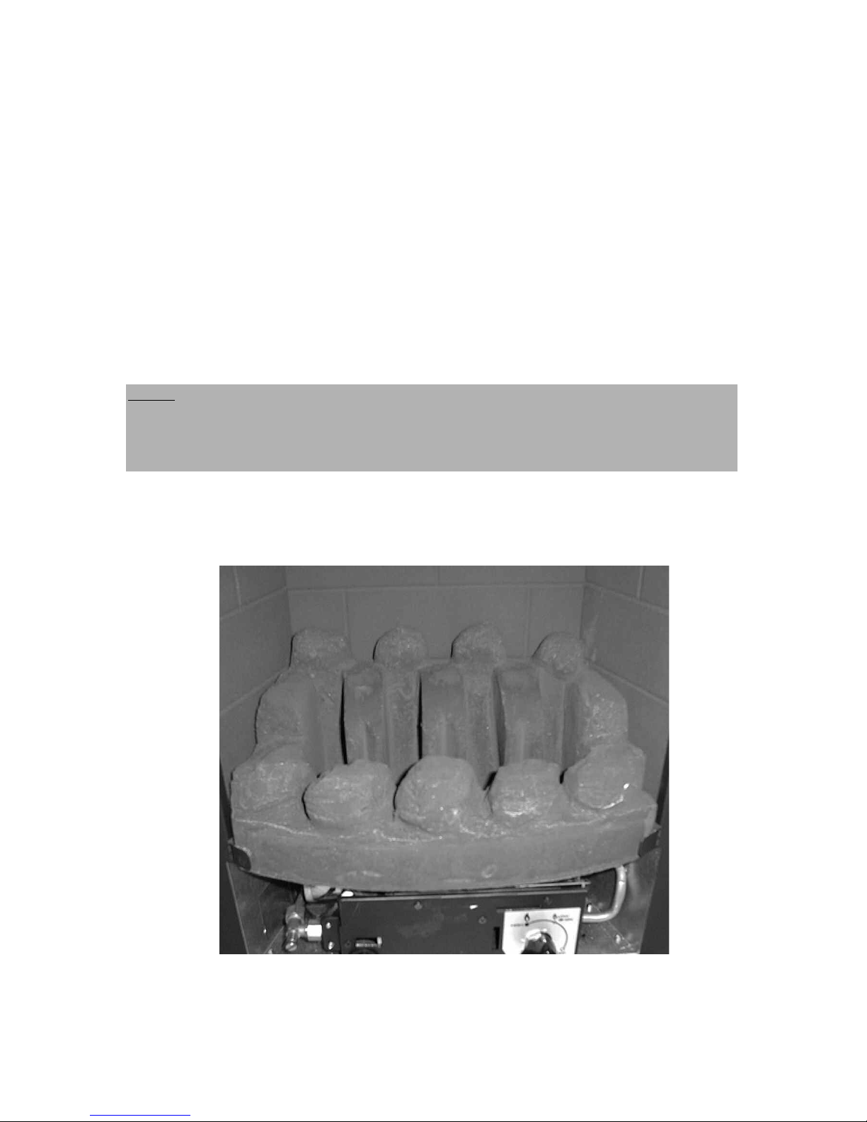
3.1 ASSEMBLING THE FUEL-BED - Coal Fuelbed Model
a) Place the fuelbed base centrally on to the fuelbed support and push
fully backwards to the rear face of the fibre boards Make sure that the
fuelbed base is located centrally in the fire box. See Fig. 10 below.
Fig. 10
17
NOTE : The position of the fuel-bed components are critical to the
performance of the product. Therefore please ensure that the fuel-bed
components are positioned as described in the following section prior to
requesting a service call due to soot build up, poor flame pattern etc.
Page 18
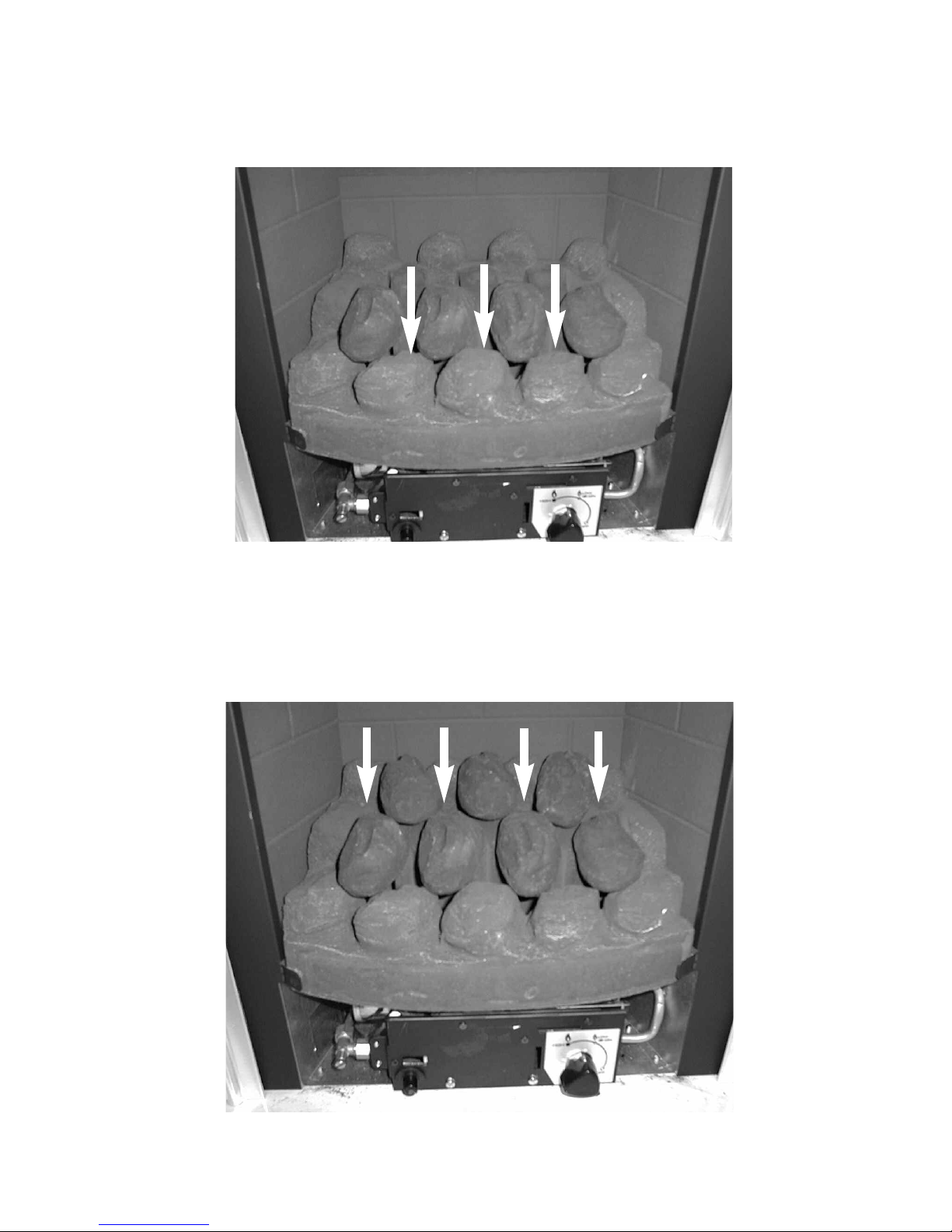
b) Position the front row of four loose coals along behind the first row of
coals, ensuring that the flame paths as indicated are not interupted.
See Fig. 11 below
Fig. 11
c) Fit the remaining three coals onto the ribs in the fuelbed as shown
below, ensuring that the rear flame paths as indicated are not interupted
See Fig. 12 below.
Fig. 12
18
Page 19
The exact position and fit of the coals may be finely adjusted to give the best
appearance.
Warning : Use only the coal set supplied with the fire. When replacing the
coals remove the old coals and discard them. Fit a complete set of coals of
the correct type. Do not fit additional coals or any coals other than a
genuine replacement set.
To ensure that the release of fibres from these R.C.F (Refractory Ceramic
Fibre) articles is kept to a minimum, during installation and servicing we
recommend that you use a HEPA filtered vacuum to remove any dust
accumulated in and around the appliance before and after working on the
appliance. When replacing these articles we recommend that the replaced
items are not broken up, but are sealed within heavy duty polythene bags,
clearly labelled as “RCF waste”. RCF waste is classed as a “stable”, non
reactive hazardous waste and may be disposed of at a landfill licensed to
accept such waste Protective clothing is not required when handling these
articles, but we recommend you follow the normal hygiene rules of not
smoking, eating or drinking in the work area, and always wash your hands
before eating or drinking.
3.2 ASSEMBLING THE FUEL-BED - Pebble Fuelbed Models
a) Place the fuelbed base centrally on to the fuelbed support and push
fully backwards to the rear face of the fibre boards Make sure that the
fuelbed base is located centrally in the fire box. See Fig. 13 below
Fig. 13
19
NOTE : The position of the fuel-bed components are critical to the
performance of the product. Therefore please ensure that the fuel-bed
components are positioned as described in the following section prior to
requesting a service call due to soot build up, poor flame pattern etc.
Page 20
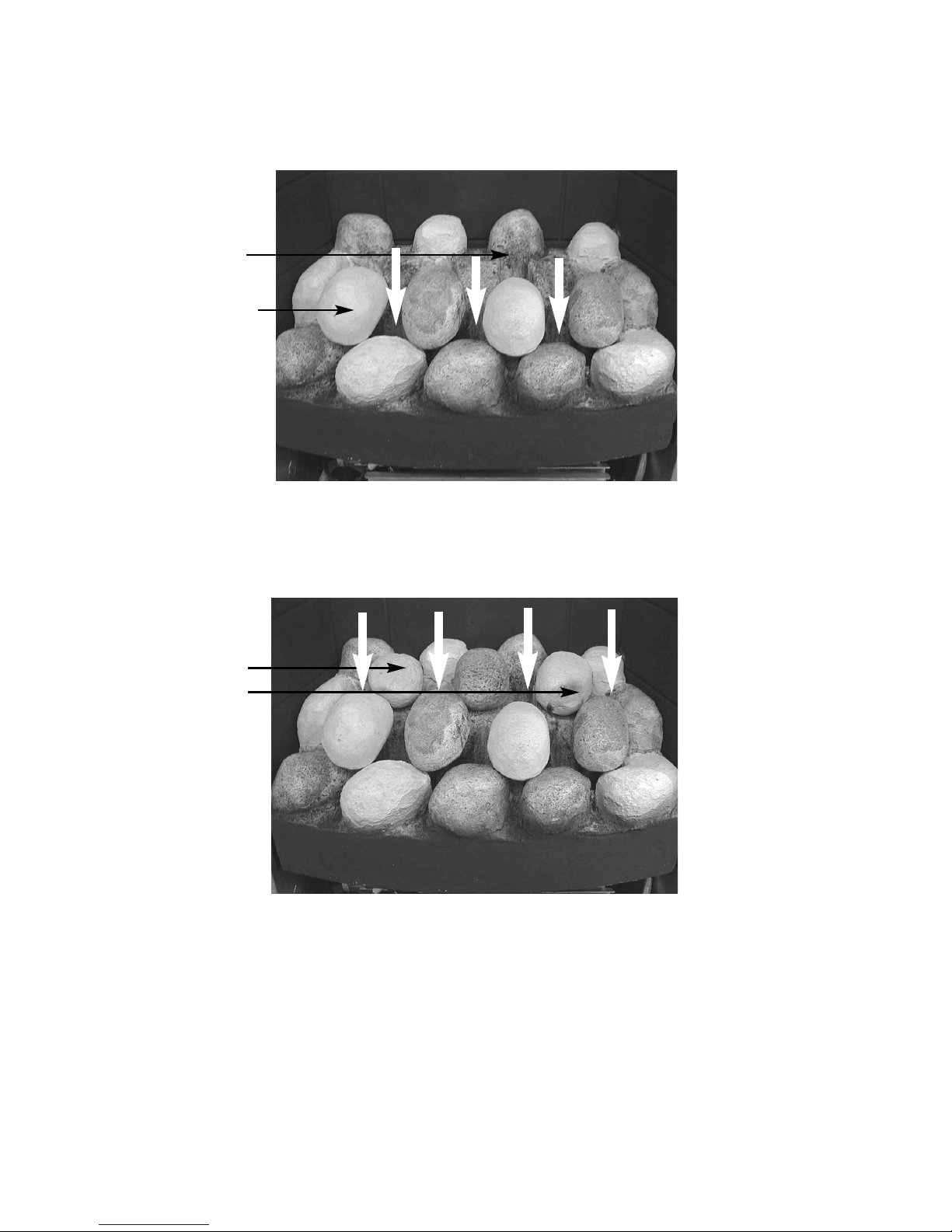
b) Position the front row of four large loose pebbles along behind the first
row of pebbles, ensuring that the flame paths as indicated are not
interupted. See Fig. 14 below
Fig. 14
c) Fit the three small pebbles onto the ribs in the fuelbed as
shown below, ensuring that the rear flame paths as indicated are
not interupted. See Fig. 15 below.
Fig. 15
The exact position and fit of the pebbles may be finely adjusted to give the
best appearance.
Warning : Use only the pebble set supplied with the fire. When replacing the
pebbles remove the old pebbles and discard them. Fit a complete
set of pebbles of the correct type. Do not fit additional pebbles or
any pebbles other than a genuine replacement set.
20
Beige Pebbles to
b
e Positioned as
s
hown
Beige Pebbles to
be positioned as
shown
Page 21
To ensure that the release of fibres from these R.C.F (Refractory Ceramic
Fibre) articles is kept to a minimum, during installation and servicing we
recommend that you use a HEPA filtered vacuum to remove any dust
accumulated in and around the appliance before and after working on the
appliance. When replacing these articles we recommend that the replaced
items are not broken up, but are sealed within heavy duty polythene bags,
clearly labelled as “RCF waste”. RCF waste is classed as a “stable”, non
reactive hazardous waste and may be disposed of at a landfill licensed to
accept such waste Protective clothing is not required when handling these
articles, but we recommend you follow the normal hygiene rules of not
smoking, eating or drinking in the work area, and always wash your hands
before eating or drinking.
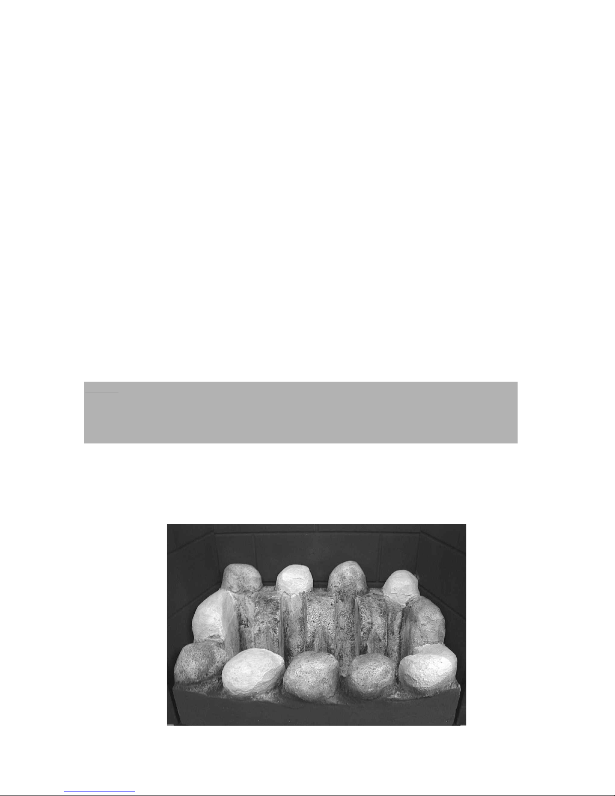
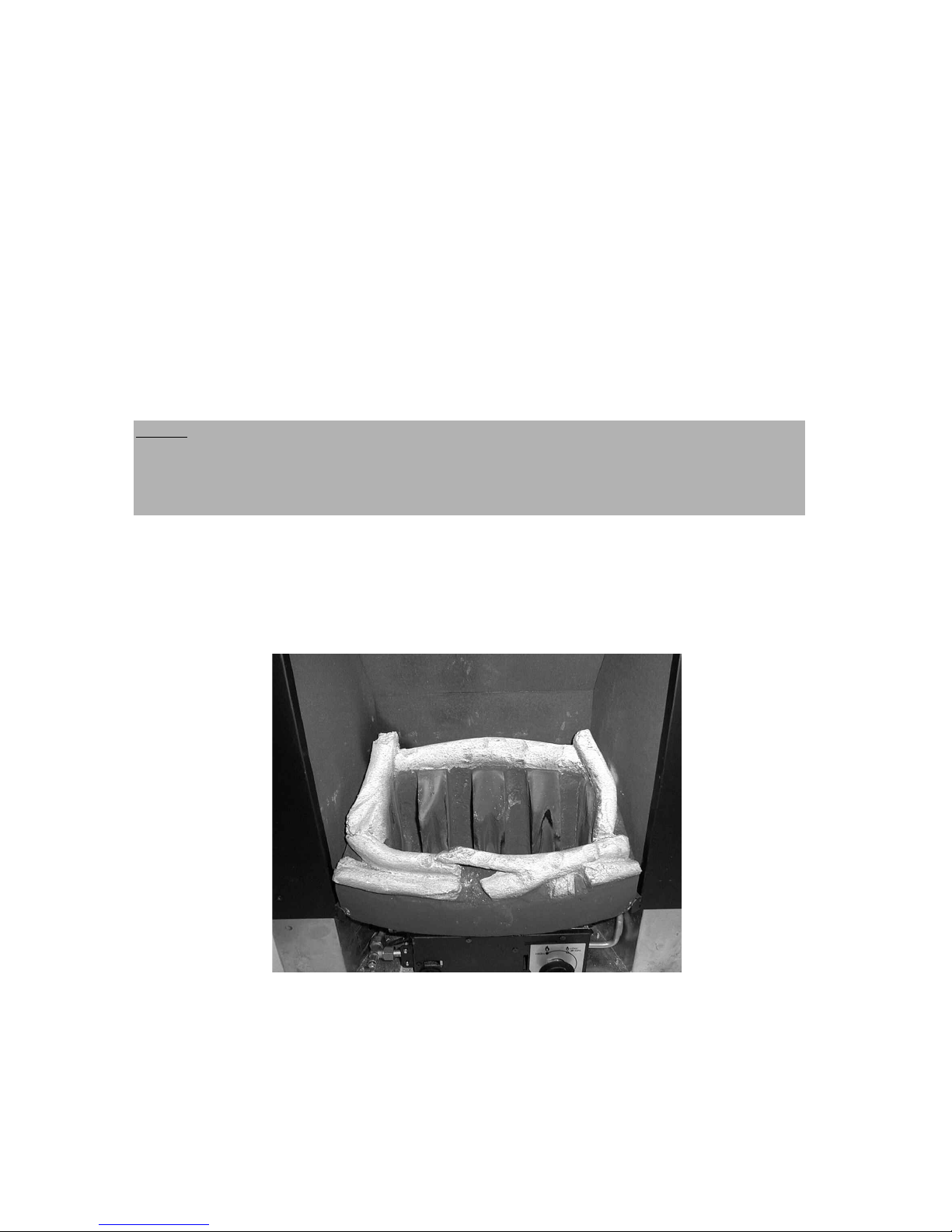
3.3 ASSEMBLING THE FUEL-BED - Driftwood Fuelbed Model
a) Place the fuelbed base centrally on to the fuelbed support and push
fully backwards to the rear face of the fibre boards Make sure that the
fuelbed base is located centrally in the fire box. See Fig. 16 below
Fig. 16
NOTE : The position of the fuel-bed components are critical to the
performance of the product. Therefore please ensure that the fuel-bed
components are positioned as described in the following section prior to
requesting a service call due to soot build up, poor flame pattern etc.
21
Page 22
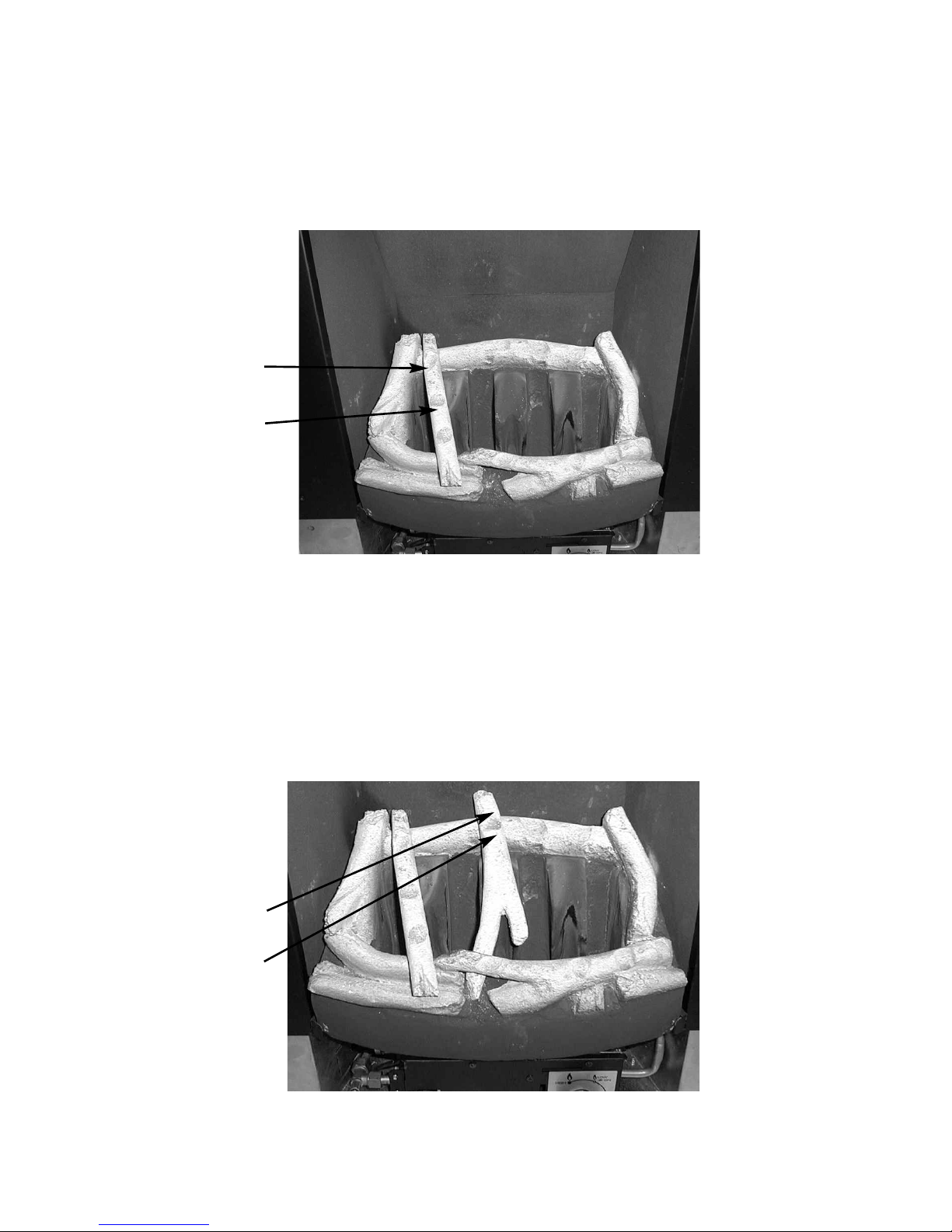
b) Position the piece of driftwood with the letter “A” stamped onto the
bottom face of it in the position at the left-hand side of the fuelbed
matrix. Ensure the positioning grooves as shown are on the top face of
the piece of driftwood. See Fig. 17 below.
Fig. 17
c) Position the piece of driftwood with the letter “B” stamped onto the
bottom face of it in the position at the centre of the fuelbed
matrix. Ensure the positioning grooves as shown are on the top face of
the piece of driftwood. See Fig. 18 below.
Fig. 18
22
Driftwood Piece “B”
Grooves in top
face as detailed in
sectrion c)
Driftwood Piece
“A”
Grooves in top
face as detailed
in sectrion b)
Page 23
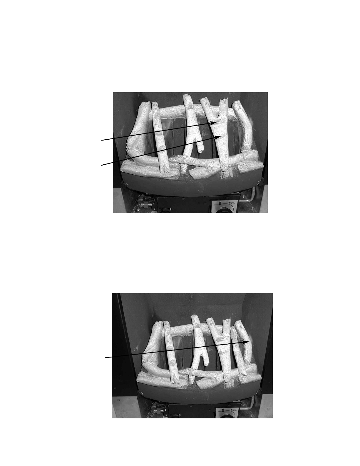
d) Position the piece of driftwood with the letter “C” stamped onto the
bottom face of it in the position at the right-hand side of the fuelbed
matrix. Ensure the positioning grooves as shown are on the top face of
the piece of driftwood. See Fig. 19 below.
Fig. 19
e) Position the piece of driftwood with the letter “D” stamped onto the
bottom face of it in the position at the right-hand side of the fuelbed
matrix. Ensure this piece of driftwood is located into the groove in the
front right hand side of the fuelbed matrix . See Fig. 20 below.
Fig. 20
23
Driftwood Piece
“D”
Locating groove
for driftwood
piece “D” in front
right hand side of
fuelbed matrix
Driftwood Piece
“C”
Grooves in top
face as detailed in
sectrion d)
Page 24
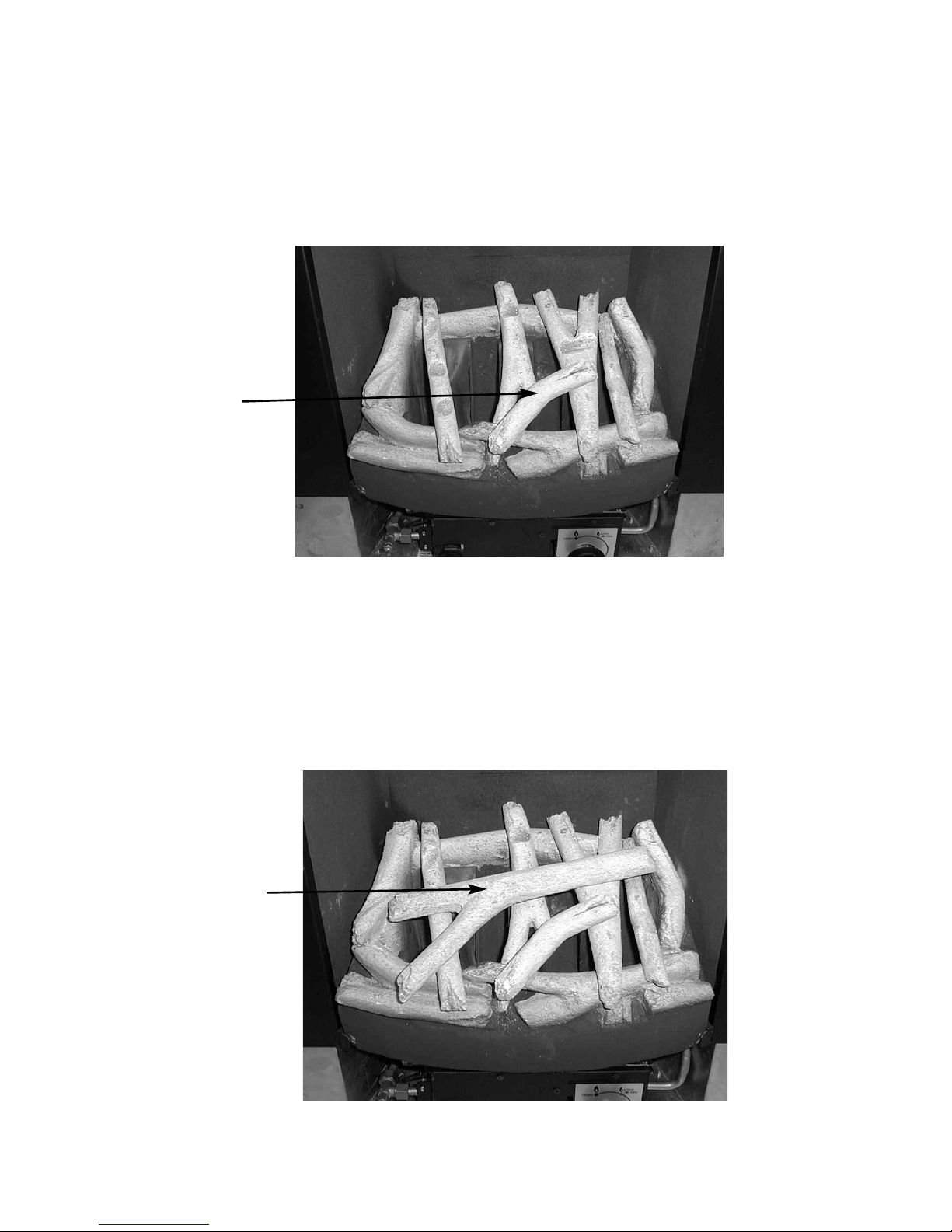
f) Position the piece of driftwood with the letter “E” stamped onto the
bottom face of it in the position at the front centre of the fuelbed
matrix. Ensure this piece of driftwood is located into the groove on
driftwood piece “C” . See Fig. 21 below.
Fig. 21
g) Position the piece of driftwood with the letter “F” stamped onto the
bottom face of it in the across the centre of the driftwood pieces “A”,
“B” & “C”. Ensure this piece of driftwood is located into the groove’s on
the top face of driftwood pieces A, B & C . See Fig. 22 below.
Fig. 22
24
Driftwood Piece “F”
Locating grooves
for driftwood piece
“F” in centre of
driftwood piece “A”,
“B” & “C”
Driftwood Piece
“E”
Locating groove
for driftwood piece
“E” in centre of
driftwood piece
“C” and in front
section of fuelbed
matrix
Page 25
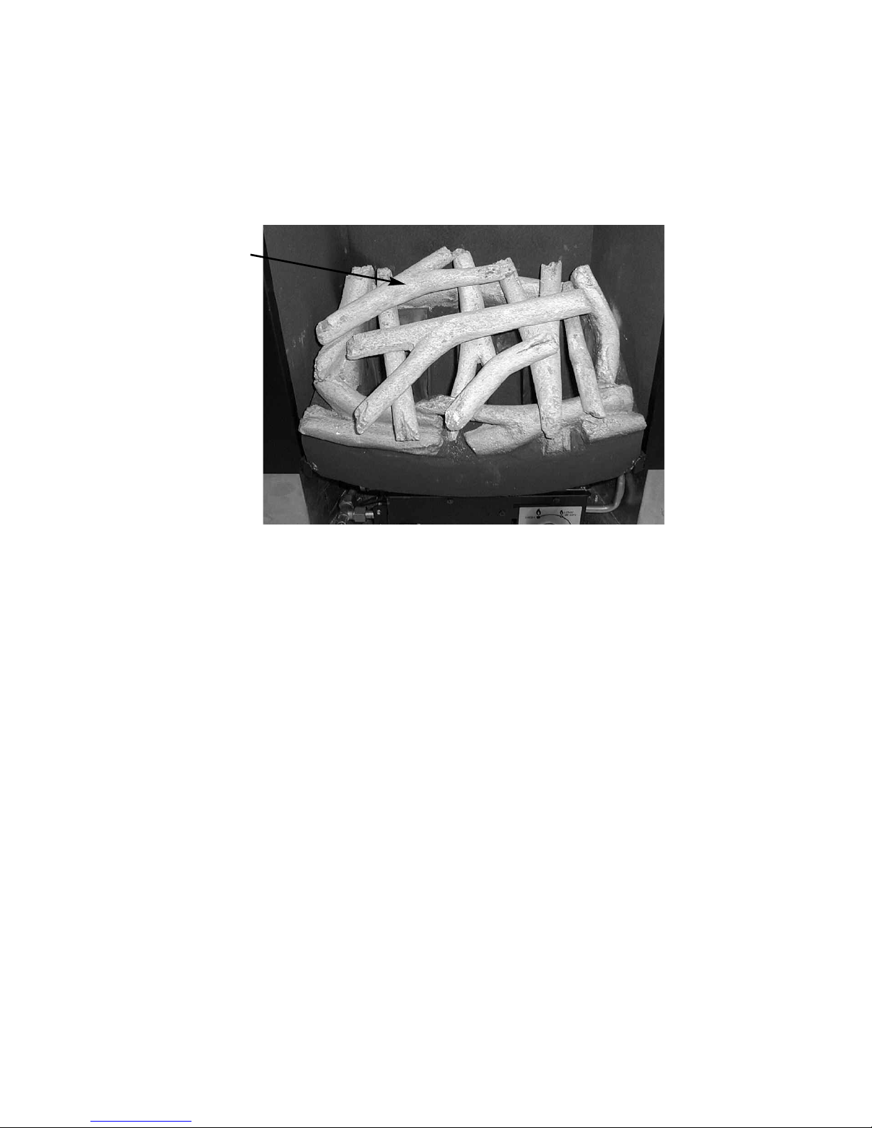
h) Position the piece of driftwood with the letter “G” stamped onto the
bottom face of it in the across the left hand side of the fuelbed matrix,
locating into the grooves on driftwood pieces “A” & “B”. See Fig. 23
below.
Fig. 23
Warning : Use only the driftwood set supplied with the fire. When replacing
the driftwood remove the old driftwood pieces and discard them. Fit a
complete set of driftwood pieces of the correct type. Do not fit additional
driftwood or any driftwood pieces other than a genuine replacement set.
To ensure that the release of fibres from these R.C.F (Refractory Ceramic
Fibre) articles is kept to a minimum, during installation and servicing we
recommend that you use a HEPA filtered vacuum to remove any dust
accumulated in and around the appliance before and after working on the
appliance. When replacing these articles we recommend that the replaced
items are not broken up, but are sealed within heavy duty polythene bags,
clearly labelled as “RCF waste”. RCF waste is classed as a “stable”, non
reactive hazardous waste and may be disposed of at a landfill licensed to
accept such waste Protective clothing is not required when handling these
articles, but we recommend you follow the normal hygiene rules of not
smoking, eating or drinking in the work area, and always wash your hands
before eating or drinking.
25
D
riftwood Piece “G”
Locating grooves
for driftwood piece
“G” in top of driftwood piece “A” &
“B”
Page 26
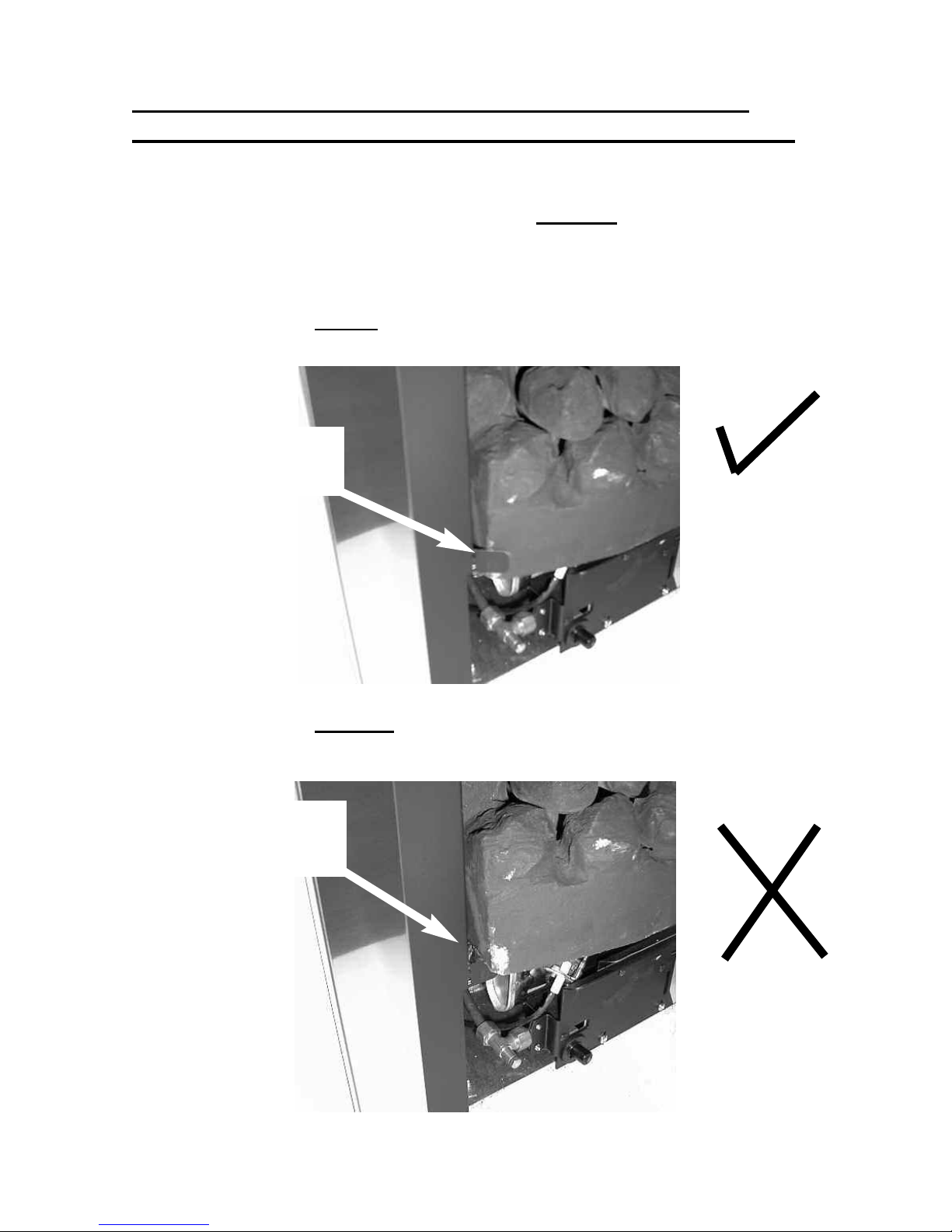
IMPORTANT INFORMATION REGARDING FUELBED
POSITION ON COAL, PEBBLE & DRIFTWOOD MODELS.
d) Before continuing with the installation, ensure
that the fuelbed is located behind the locating
tabs as shown below in Fig. 24, not on top of the
locating tabs as shown in Fig. 25
Fig. 24 - Shows correct location of fuelbed
Fig. 25 - Shows incorrect
location of fuelbed
26
Fuelbed correctly
positioned behind
locating tabs
Fuelbed incorrectly
positioned on top of
the locating tabs
Page 27

3.4 FITTING THE TRIM
Models supplied with three piece trim
a) Fit the 2 side pieces of the trim by overlapping the lips of the trim
over the side lips of the firebox, and securing with the magnets
provided
b) Fit the top piece of the trim by overlapping the lips of the trim over
the lips of the firebox and over the 2 side trims.
Models supplied with one piece trim
a) Fit the outer trim assembly to the firebox with the magnets
provided.
3.5 FITTING THE FRET (ONLY APPLICABLE TO MODELS SUPPLIED
WITH A FRET FROM THE FACTORY)
a) Remove the fret & ashpan cover from the packaging.
b) Place fret up to the front radiused section of the fuelbed, taking care
not to move coal positions.
c) Place ashpan cover under fret assembly and centralise.
PLEASE NOTE
: TO INCREASE CUSTOMER CHOICE, SOME MODELS
WITHIN THIS RANGE ARE NOW SUPPLIED WITH A FRET DIRECTLY BY THE
RETAILER, AND ONLY THE TRIM IS FACTORY SUPPLIED.
THEREFORE, PLEASE CONSULT YOUR RETAILER FOR ADVICE ON FITTING
AND CLEANING INSTRUCTIONS FOR THESE TYPES OF FRETS.
27
Page 28

3.6 LIGHTING THE APPLIANCE (All models)
a) Turn on the gas isolation tap.
b) Depress the control knob and turn anti-clockwise to the position
marked ignition / low rate. Hold in the control knob for a few seconds to
purge the pipe work.
c) Continue to hold-in the control knob and press the igniter button. If the
burner does not light, continue to press the igniter button until ignition
occurs. Continue to hold the control knob for a minimum of 20 seconds
to allow the thermocouple to heat up, if the burner goes out when the
control knob is released, repeat the lighting sequence.
d) Turn the control knob in the anti-clockwise direction to the high position
and the gas rate will increase to high rate (6.5 kW)
e) Turn the control knob clockwise to the low position and the gas input
will be reduced to the minimum setting (2.2 kW)
f) Slightly depress the control knob and turn to the off position, the burner
will now be extinguished.
WARNING : If the fire goes out for any reason or is turned off and it
is necessary to re-light the fire it is important to allow the
fire to cool for 3 minutes before attempting to re-light it.
3.7 CHECKING FOR CLEARANCE OF COMBUSTION PRODUCTS
a) Close all doors and windows in the room.
b) Light the fire and allow to run for approximately 5 minutes on high
position.
c) After approximately 5 minutes hold a smoke match just inside and
below the centre of the lower front edge of the top of the fire. (It is
recommended that a suitable smoke match holder is used when check
ing for clearance of combustion products). All smoke generated should
be drawn back into the flue. If slight spillage occurs or if in doubt,
repeat the test after a further 5-10 minutes. If the test indicates that
spillage is occurring and the flue restrictor baffle has been fitted, it
should be removed and the test repeated after the fire has cooled.
d) If spillage persists, the flue is not functioning correctly and a fault exists.
If, after investigation the fault cannot be traced and rectified, the fire
must be disconnected from the gas supply and expert advice obtained.
28
Page 29

e) If there is an extractor fan fitted any where in the vicinity of the
appliance, or in adjacent rooms the spillage test should be repeated
with the fan running on maximum and all interconnecting doors open.
f) After ensuring that the fire is safe to use it should be left on high
position to fully warm up. During this time a slight odour may be
noticed, this is due to the “newness” of the fire and will soon disappear.
At this stage any minor adjustments to the pebbles should be made
using suitable long handled tongs and taking care not to damage the
pebbles.
Finally, hand the Installation and Maintenance Instructions and the
Users Instructions over to the customer and explain the operation of the
fire.
29
Page 30

SECTION 4
MAINTENANCE
Servicing Notes
Servicing should be carried out annually by a competent person such as a GAS
SAFE registered engineer. This is a condition of the BFM Europe guarantee
schemes.
The service should include visually checking the chimney and fire opening for
accumulations of debris and a smoke test to check for a positive up-draught in the
chimney.
The condition of the coals should be checked and if necessary the whole set
should be replaced with a genuine replacement set.
The burner assembly is designed to be removed as a complete unit for ease of
access. After any servicing work a gas tightness check must always be
carried out. All sections apply for both coal and pebble fuelbed model
variants.
For Diagrams refer to Section 2
4.1 Removing the burner assembly from the fire.
4.1.1 Prepare work area (lay down dust sheets etc.)
4.1.2 Remove the magnetic trim. Remove the fret / ash pan cover or
contemporary trim out of the way and put them in a safe location.
Remove the loose coals, pebbles or driftwood from the fuel bed.
Remove the fuelbed matrix.
4.1.3 Isolate the gas supply and remove the inlet pipe from the appliance
inlet elbow. Unscrew and remove the two screws which retain the
burner at the base. Lift the burner retaining tabs from the rear of the
firebox & remove the burner assembly from the fire.
4.1.4 To refit the burner assembly. Push the retaining tabs into the rear panel
of the firebox and secure the burner at the base of the control panel
with two screws. Refit the gas supply pipe and carry out a gas
tightness test. Refit the burner heat shield then refit the coals, driftwood
or pebbles referring to section 3 for the correct layout. The trim and ash
pan cover or contemporary trim can now be re-positioned.
4.2 Removing the Piezo Igniter
4.2.1 Remove the burner assembly as in section 4.1
4.2.2 Disconnect the ignition lead from the piezo and unscrew the
retaining nut on the rear of the control panel. Withdraw the piezo from
the front of the control panel. Re-assemble in reverse order and carry
out a gas tightness test.
30
Page 31

4.3 Removing the Control Tap from the fire.
4.3.1 Remove the burner assembly as in section 4.1.
4.3.2 Pull the control knob off the control tap spindle.
4.3.3 Loosen and remove the two gas pipe retaining nuts from the control
tap and release the ends of the gas pipes from the control tap body.
Remove the push in thermocouple from the end of the control tap.
4.3.4 Unscrew the control tap locknut from the front of the control panel and
remove the control tap.
4.3.5 To refit a control tap, reassemble in reverse order noting that the control
tap locates with a flat in the control panel. Carry out a gas tightness
test after re-assembly.
4.4 Removing the Thermocouple
4.4.1 Remove the burner assembly as in section 4.1
4.4.2 Remove the push in thermocouple from the end of the control tap and
and remove the thermocouple retaining nut from the mounting bracket
on the burner assembly.
4.4.3 Re-assemble in reverse order and carry out a gas tightness test.
PARTS SHORTLIST
Replacement of any other parts must be carried out by a competent person such
as a GAS SAFE registered gas installer. The part numbers of the main replaceable parts are as follows, these are available from your local Global Stockist,
whose details can be obtained from BFM Europe.
Coal Pack B-67050 Coal Fuelbed Matrix B-67040
Pebble Pack B-68240 Pebble Fuelbed Matrix B-68230
L/H Fibre Board (Plain) B-67550 L/H Fibre Board (Brick Back) B-68170
R/H Fibre Board (Plain) B-67560 R/H Fibre Board (Brick Back) B-68160
Lower Fibre Board (Plain) B-67540 Lower Rear Fibre Board B-68150
Upp. Rear Fibre Board (Plain) B-67530 Upper Rear Fibre Board B-68140
Gas Valve B-67090 Driftwood Fuelbed Matrix B-81160
Burner Engine B-67890 Driftwood Pack B-81170
Ignition Wire B-67910
31
Page 32

SECTION FIVE - USER INSTRUCTIONS
5.1 Installation Information
Conditions of Installation
It is the law that all gas appliances are installed only by a competent (e.g. GAS
SAFE Registered) Installer, in accordance with the installation instructions and the
Gas Safety (Installation and Use) Regulations 1998. Failure to install appliances
correctly could lead to prosecution. It is in your own interest and that of safety to
comply with the law.
The fire may be fitted below a combustible shelf provided that the shelf is at least
200mm above the top of the appliance and the depth of the shelf does not exceed
150mm.
The fire may be installed below combustible shelves which exceed 150mm deep
providing that the clearance above the fire is increased by 15mm for each 25mm
of additional overhang in excess of 150mm.
No purpose made additional ventilation is normally required for this
appliance when installed in G.B. When installed I.E. please consult
document I.S. 813 : 1996 Domestic Gas Installation which is issued by the
National Standards Authority of Ireland. Any purpose made ventilation
should be checked periodically to ensure that it is free from obstruction.
If the chimney or flue has been previously used by appliances burning fuels other
than gas they must be swept prior to the installation of this fire.
If this appliance is fitted directly on to a wall without the use of a fireplace or surround, soft wall coverings such as wallpaper, blown vinyl etc. could be affected by
the heat and hot air and may discolour or scorch. This should be considered
when installing or decorating.
The Model number of this appliance is as stated on the rating plate affixed to the
control panel of the fire and the appliance is manufactured by:-
BFM Europe Ltd.
Trentham Lakes
Stoke on Trent
ST4 4TJ
32
Page 33

About your Global Karara
The Global Karara Multiflue range of coal, pebble & driftwood fuel-bed gas fires
incorporates a unique and highly developed fuel bed which gives the realism of a
loose coal or pebble layout combined with realistic flames and glow. The use of
durable ceramic material in the construction of the fuel-bed components ensures
long and trouble free operation.
When first using the new fire a slight smell may be noticed. This is due to starch
used in the manufacture of the soft ceramic coals or pebbles, it is non-toxic and
will soon disappear.
Please take the time to fully read these instructions as you will then be able to
obtain the most effective and safe operation of your fire.
IMPORTANT SAFETY INFORMATION
WARNING
This appliance has a naked flame and as with all heating appliances a
fireguard should be used for the protection of children, the elderly and
infirm. Fireguards should conform to B.S. 8423 : 2002 (Fireguards for use
with gas heating appliances).
It is important that this appliance is serviced at least once a year by a GAS SAFE
registered gas installer and that during the service the fire is removed from the fire
opening and the chimney or flue visually checked for fallen debris or blockages
which must be removed. The chimney should also be checked to ensure
clearance of flue products. These are conditions of the manufacturers
guarantee. After installation or during servicing a spillage test must always
be carried out.
Rubbish of any type must NEVER be thrown onto the fuel-bed, this could affect
safe operation and damage the fire.
Any debris or deposits should be removed from the fuel-bed from time to time.
This may be carried out by referring to the cleaning section as described later in
this book.
Only the correct number and type of pebbles, coals or driftwood must be used and
only complete and genuine replacement sets must be sourced from BFM Europe
Ltd. The appliance must only be used with the coal pebble or driftwood set
supplied and must not be used with other coals, pebbles or driftwood
Always keep furniture and combustible materials well clear of the fire and never
dry clothing or items either on or near to the fire. Never use aerosols or
flammable cleaning products near to the fire when it is in use.
33
Page 34

The ceramic fuel-bed remains hot for a considerable period after use and
sufficient time should be allowed for the fire to cool before cleaning etc.
The fire must only be operated with the trim and fret supplied with the fire.
5.2 Operating the Fire
The controls are located behind the ashpan cover which is situated below the
fret or contemporary ashpan cover. The controls, comprise a control valve to
adjust the gas flow and a push button piezo igniter. To light the fire proceed as
follows:-
1) Depress the control knob and turn anti-clockwise to the position
marked ignition rate. Hold in the control knob for a few seconds to allow the
gas to reach the burner.
2) Continue to hold-in the control knob and press the igniter button. If the
burner does not light, continue to press the igniter button until ignition occurs.
When the pilot has lit, continue to hold the control knob in for a minimum of
20 seconds to allow the thermocouple to heat up, if the burner goes out
when the control knob is released, repeat the lighting sequence.
In the unlikely event of a failure of the igniter, the fire can be lit as follows :Depress the control knob and turn anti-clockwise to the position
marked ignition rate. Hold in the control knob for a few seconds to allow the gas
to reach the burner. Insert the tip of a lit taper in below the fuelbed ceramic matrix
above the thermocouple tip. This will light the main burner at low rate.
3) After lighting, turn the control knob in the anti-clockwise direction to the high
position. It is recommended that for most efficient performance the fire is
allowed to warm up for a few minutes with the gas control on maximum.
4) The gas control can be turned clockwise from the maximum position to give
the desired heat output.
WARNING
If the fire goes out for any reason or is turned off and it is
necessary to re-light the fire it is important to allow the fire to cool
for 3 minutes before attempting to re-light it.
SPILLAGE MONITORING SYSTEM
This appliance is fitted with a spillage monitoring system which shuts down the fire
if the evacuation of combustion products from the fire is affected by a partially or
fully blocked flue. If this system operates the fire will go out. If this occurs, leave
the fire for at least three minutes then follow the lighting procedure as described in
the previous section. In the event of repeated operation a GAS SAFE
registered gas installer must be called to investigate and rectify the cause.
34
Page 35
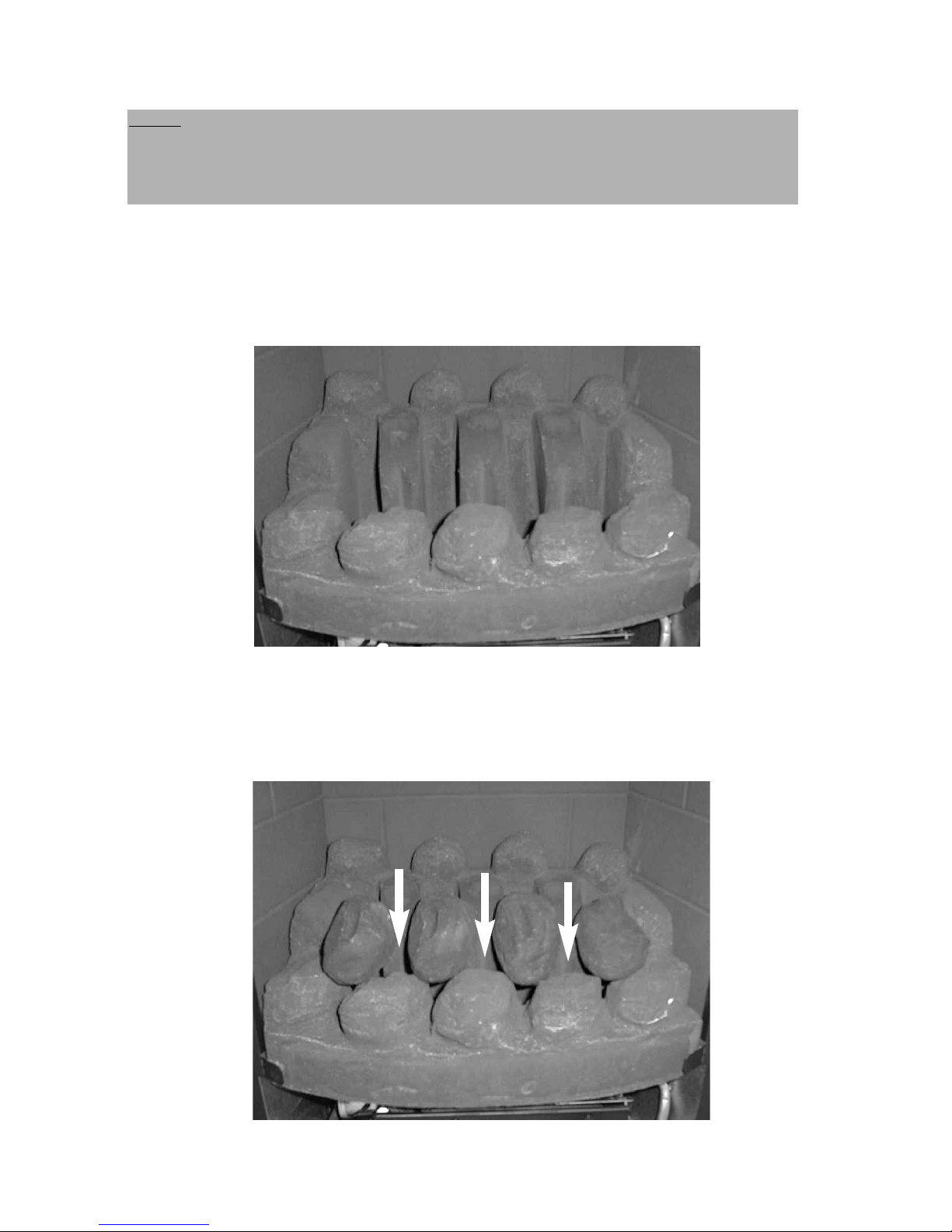
5.3 ASSEMBLING THE FUEL-BED - Coal Fuelbed Model
a) Place the fuelbed base centrally on to the fuelbed support and push
fully backwards to the rear face of the fibre boards Make sure that the
fuelbed base is located centrally in the fire box. See Fig. 26 below.
Fig. 26
b) Position the front row of four loose coals along behind the first row of
coals, ensuring that the flame paths as indicated are not interupted.
See Fig. 27 below
Fig. 27
35
NOTE : The position of the fuel-bed components are critical to the
performance of the product. Therefore please ensure that the fuel-bed
components are positioned as described in the following section prior to
requesting a service call due to soot build up, poor flame pattern etc.
Page 36
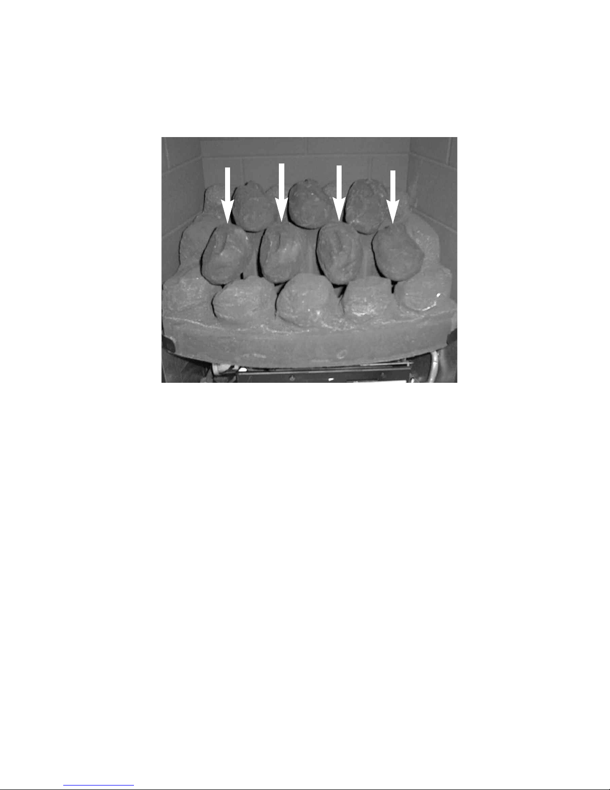
c) Fit the remaining three coals onto the ribs in the fuelbed as shown
below, ensuring that the rear flame paths as indicated are not interupted
See Fig. 28 below.
Fig. 28
The exact position and fit of the coals may be finely adjusted to give the best
appearance.
Warning : Use only the coal set supplied with the fire. When replacing the
coals remove the old coals and discard them. Fit a complete set of coals of
the correct type. Do not fit additional coals or any coals other than a
genuine replacement set.
To ensure that the release of fibres from these R.C.F (Refractory Ceramic
Fibre) articles is kept to a minimum, during installation and servicing we
recommend that you use a HEPA filtered vacuum to remove any dust
accumulated in and around the appliance before and after working on the
appliance. When replacing these articles we recommend that the replaced
items are not broken up, but are sealed within heavy duty polythene bags,
clearly labelled as “RCF waste”. RCF waste is classed as a “stable”, non
reactive hazardous waste and may be disposed of at a landfill licensed to
accept such waste Protective clothing is not required when handling these
articles, but we recommend you follow the normal hygiene rules of not
smoking, eating or drinking in the work area, and always wash your hands
before eating or drinking.
36
Page 37
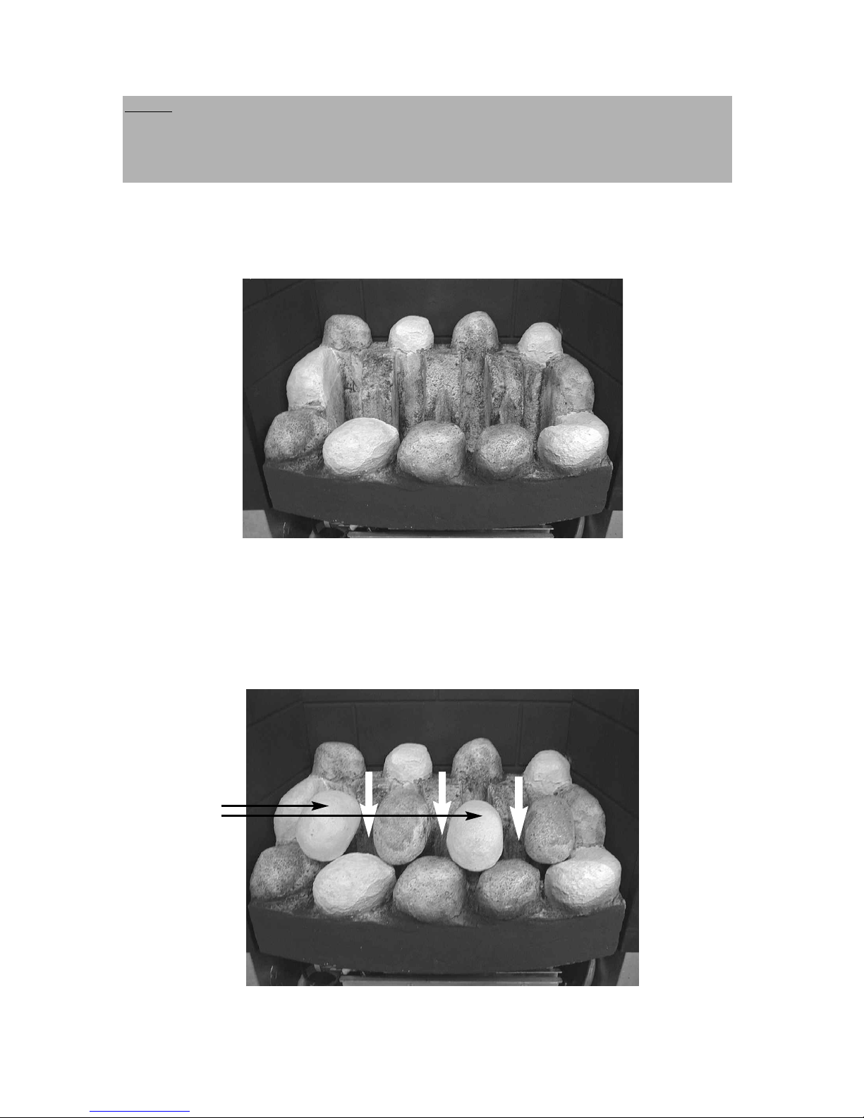
5.4 ASSEMBLING THE FUEL-BED - Pebble Fuelbed Model
a) Place the fuelbed base centrally on to the fuelbed support and push
fully backwards to the rear face of the fibre boards Make sure that the
fuelbed base is located centrally in the fire box. See Fig. 29 below
Fig. 29
b) Position the front row of four large loose pebbles along behind the first
row of pebbles, ensuring that the flame paths as indicated are not
interupted. See Fig. 30 below
Fig. 30
37
Beige pebbles
to be positioned
as indicated
NOTE : The position of the fuel-bed components are critical to the
performance of the product. Therefore please ensure that the fuel-bed
components are positioned as described in the following section prior to
requesting a service call due to soot build up, poor flame pattern etc.
Page 38
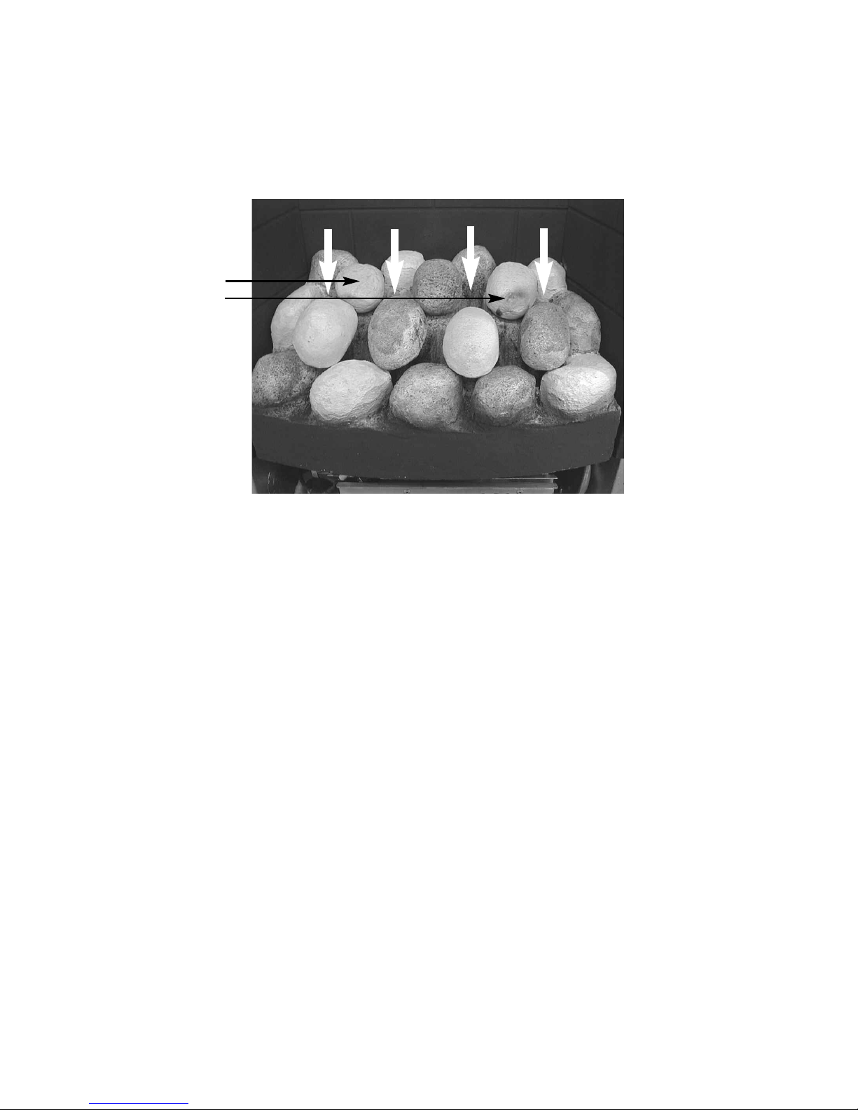
c) Fit the three small pebbles onto the ribs in the fuelbed as
shown below, ensuring that the rear flame paths as indicated are
not interupted. See Fig. 31 below.
Fig. 31
The exact position and fit of the pebbles may be finely adjusted to give the
best appearance.
Warning : Use only the pebble set supplied with the fire. When replacing the
pebbles remove the old pebbles and discard them. Fit a complete
set of pebbles of the correct type. Do not fit additional pebbles or
any pebbles other than a genuine replacement set.
To ensure that the release of fibres from these R.C.F (Refractory Ceramic
Fibre) articles is kept to a minimum, during installation and servicing we
recommend that you use a HEPA filtered vacuum to remove any dust
accumulated in and around the appliance before and after working on the
appliance. When replacing these articles we recommend that the replaced
items are not broken up, but are sealed within heavy duty polythene bags,
clearly labelled as “RCF waste”. RCF waste is classed as a “stable”, non
reactive hazardous waste and may be disposed of at a landfill licensed to
accept such waste Protective clothing is not required when handling these
articles, but we recommend you follow the normal hygiene rules of not
smoking, eating or drinking in the work area, and always wash your hands
before eating or drinking.
38
B
eige pebbles to
be positioned as
indicated
Page 39
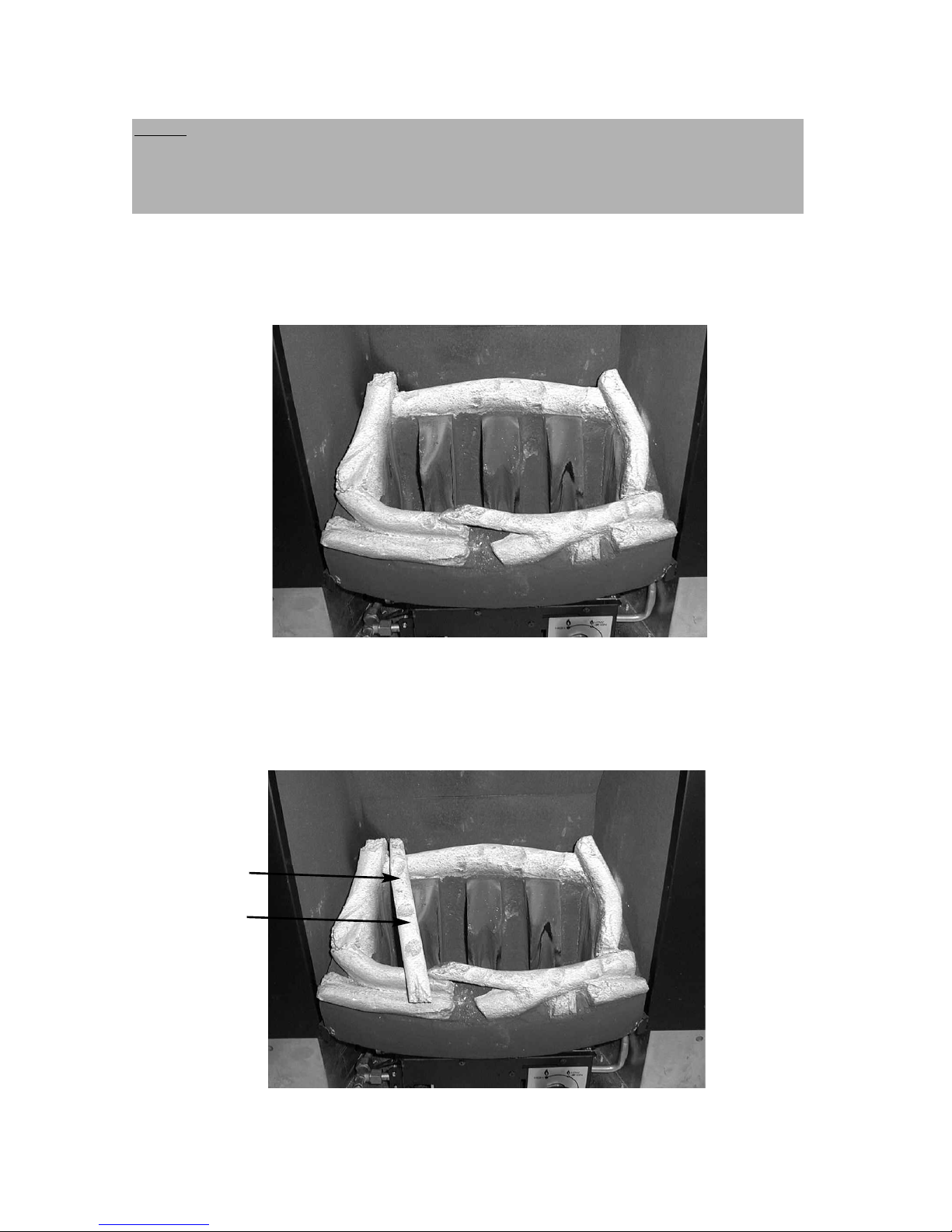
5.5 ASSEMBLING THE FUEL-BED - Driftwood Fuelbed Model
a) Place the fuelbed base centrally on to the fuelbed support and push
fully backwards to the rear face of the fibre boards Make sure that the
fuelbed base is located centrally in the fire box. See Fig. 32 below
Fig. 32
b) Position the piece of driftwood with the letter “A” stamped onto the
bottom face of it in the position at the left-hand side of the fuelbed
matrix. Ensure the positioning grooves as shown are on the top face of
the piece of driftwood. See Fig. 33 below.
Fig. 33
39
Driftwood Piece “A”
Grooves in top face
as detailed in
section b)
NOTE : The position of the fuel-bed components are critical to the
performance of the product. Therefore please ensure that the fuel-bed
components are positioned as described in the following section prior to
requesting a service call due to soot build up, poor flame pattern etc.
Page 40
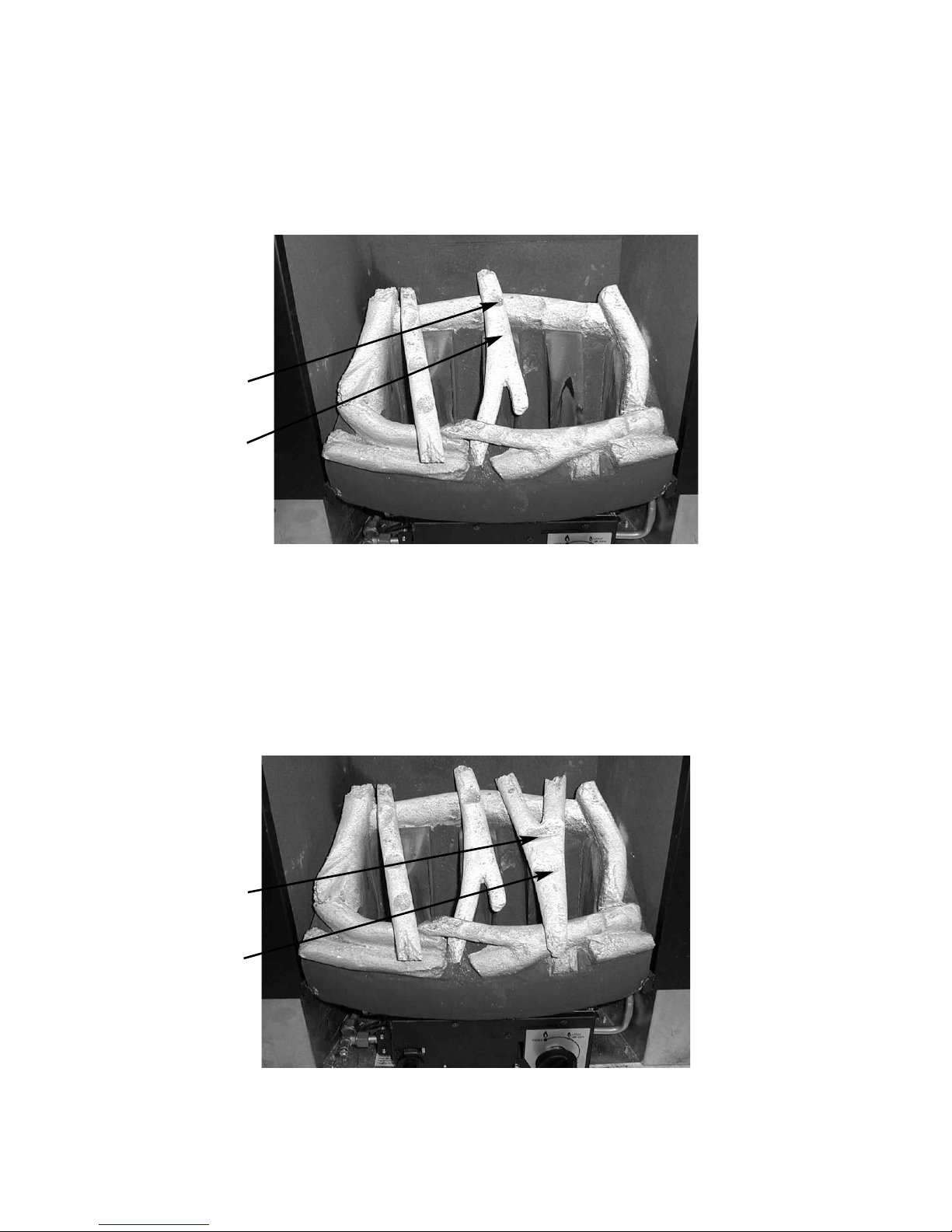
c) Position the piece of driftwood with the letter “B” stamped onto the
bottom face of it in the position at the centre of the fuelbed
matrix. Ensure the positioning grooves as shown are on the top face of
the piece of driftwood. See Fig. 34 below.
Fig. 34
d) Position the piece of driftwood with the letter “C” stamped onto the
bottom face of it in the position at the right-hand side of the fuelbed
matrix. Ensure the positioning grooves as shown are on the top face of
the piece of driftwood. See Fig. 35 below.
Fig. 35
Driftwood Piece
“B”
Grooves in top
face as detailed in
sectrion c)
Driftwood Piece
“C”
Grooves in top
face as detailed in
sectrion d)
40
Page 41
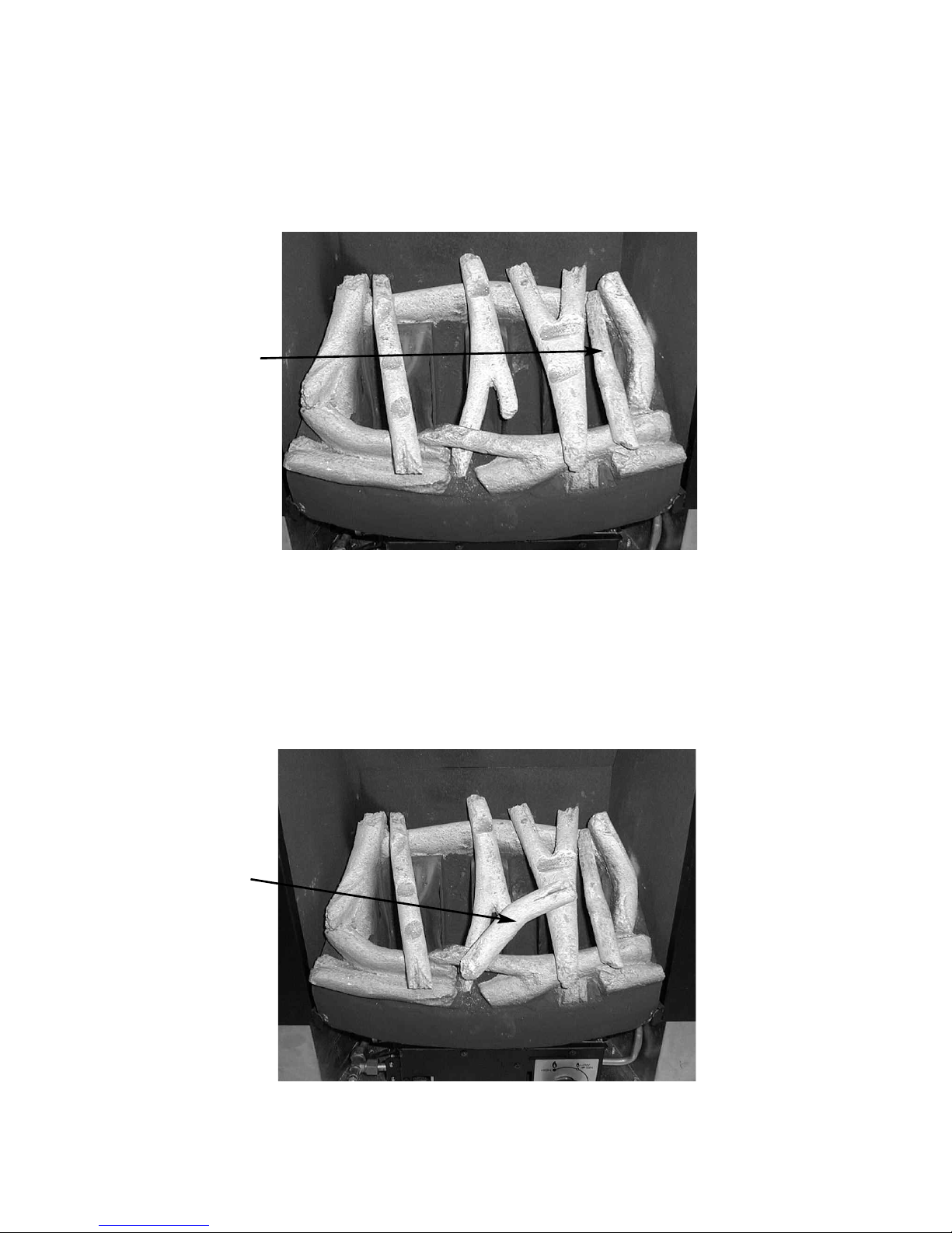
e) Position the piece of driftwood with the letter “D” stamped onto the
bottom face of it in the position at the right-hand side of the fuelbed
matrix. Ensure this piece of driftwood is located into the groove in the
front right hand side of the fuelbed matrix . See Fig. 36 below.
Fig. 36
f) Position the piece of driftwood with the letter “E” stamped onto the
bottom face of it in the position at the front centre of the fuelbed
matrix. Ensure this piece of driftwood is located into the groove on
driftwood piece “C” . See Fig. 37 below.
Fig. 37
Driftwood Piece “D”
Locating groove for
driftwood piece “D”
in front right hand
side of fuelbed
matrix
Driftwood Piece “E”
Locating groove for
driftwood piece “E”
in centre of driftwood piece “C”
and in front section
of fuelbed matrix
41
Page 42
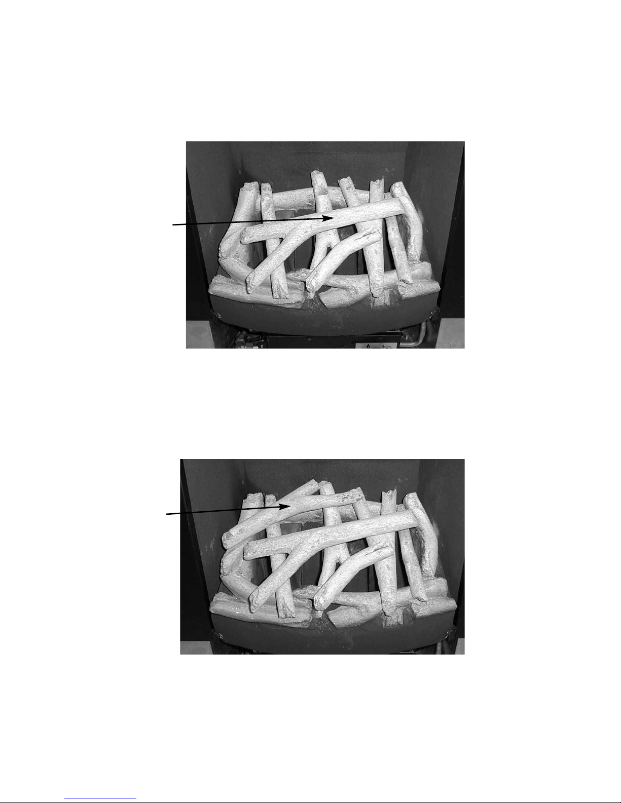
g) Position the piece of driftwood with the letter “F” stamped onto the
bottom face of it in the across the centre of the driftwood pieces “A”,
“B” & “C”. Ensure this piece of driftwood is located into the groove’s on
the top face of driftwood pieces A, B & C . See Fig. 38 below.
Fig. 38
h) Position the piece of driftwood with the letter “G” stamped onto the
bottom face of it in the across the left hand side of the fuelbed matrix,
locating into the grooves on driftwood pieces “A” & “B”. See Fig. 39
below.
Fig. 39
Driftwood Piece “F”
Locating grooves for
driftwood piece “F” in
centre of driftwood
piece “A”, “B” & “C”
Driftwood Piece “G”
Locating grooves for
driftwood piece “G”
in top of driftwood
piece “A” & “B”
42
Page 43

Warning : Use only the driftwood set supplied with the fire. When replacing
the driftwood remove the old driftwood pieces and discard them. Fit a
complete set of driftwood pieces of the correct type. Do not fit additional
driftwood or any driftwood pieces other than a genuine replacement set.
To ensure that the release of fibres from these R.C.F (Refractory Ceramic
Fibre) articles is kept to a minimum, during installation and servicing we
recommend that you use a HEPA filtered vacuum to remove any dust
accumulated in and around the appliance before and after working on the
appliance. When replacing these articles we recommend that the replaced
items are not broken up, but are sealed within heavy duty polythene bags,
clearly labelled as “RCF waste”. RCF waste is classed as a “stable”, non
reactive hazardous waste and may be disposed of at a landfill licensed to
accept such waste Protective clothing is not required when handling these
articles, but we recommend you follow the normal hygiene rules of not
smoking, eating or drinking in the work area, and always wash your hands
before eating or drinking.
43
Page 44
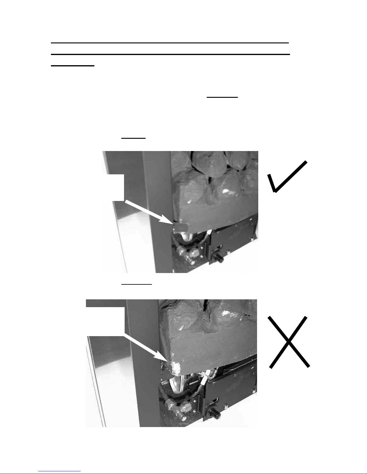
IMPORTANT INFORMATION REGARDING FUELBED
POSITION ON BOTH COAL, PEBBLE & DRIFTWOOD
MODELS.
d) Before continuing with the installation, ensure
that the fuelbed is located behind the locating
tabs as shown below in Fig. 40, not on top of the
locating tabs as shown in Fig. 41
Fig. 40 - Shows correct location of fuelbed
Fig. 41 - Shows incorrect
location of fuelbed
44
Fuelbed correctly
positioned behind
locating tabs
Fuelbed incorrectly
positioned on top of
the locating tabs
Page 45

5.6 Cleaning - WARNING
Before attempting any cleaning operation ensure that the fire has been allowed to
fully cool. The Brass fret that was supplied with the fire (dependent upon model
chosen) is real brass and therefore will discolour with use and should be cleaned
with a proprietory metal polish. The chrome & brass effect trims, contemporary
trims and chrome effect fret that was supplied with the fire (dependent upon model
chosen) should only be cleaned with a clean, damp cloth.
The trim is best cleaned in position on the fire when the appliance is not running
and is cool. Black painted metal parts should be gently cleaned with a damp cloth.
Cleaning the Fuelbed
We do not recommend cleaning of the coals or fuelbed components as these are
fragile and damage may result. None of these parts must be washed or
exposed to any cleaning agents or water. Any damaged parts must be
replaced by contacting your dealer or telephoning BFM Europe on the number
stated on the rear cover of this book. The coals, pebbles or driftwood must only
be replaced with a complete and genuine replacement set and the fire must never
be run with the wrong number or damaged coals / pebbles / driftwood. The fuelbed must be carefully re-assembled as stated in section 5.4, 5.5 & 5.6 (dependent
upon model chosen), pages 35-44
FITTING THE TRIM
Models supplied with three piece trim
a) Fit the 2 side pieces of the trim by overlapping the lips of the trim
over the side lips of the firebox, and securing with the magnets
provided
b) Fit the top piece of the trim by overlapping the lips of the trim over
the lips of the firebox and over the 2 side trims.
Models supplied with one piece trim
a) Fit the outer trim assembly to the firebox with the magnets
provided.
FITTING THE FRET (ONLY APPLICABLE TO MODELS SUPPLIED
WITH A FRET FROM THE FACTORY)
a) Remove the fret & ashpan cover from the packaging.
b) Place fret up to the front radiused section of the fuelbed, taking care
not to move coal positions.
45
Page 46

c) Place ashpan cover under fret assembly and centralise.
PLEASE NOTE
: TO INCREASE CUSTOMER CHOICE, SOME MODELS
WITHIN THIS RANGE ARE NOW SUPPLIED WITH A FRET DIRECTLY BY THE
RETAILER, AND ONLY THE TRIM IS FACTORY SUPPLIED.
THEREFORE, PLEASE CONSULT YOUR RETAILER FOR ADVICE ON FITTING
AND CLEANING INSTRUCTIONS FOR THESE TYPES OF FRETS.
USER REPLACEABLE PARTS
The only user replaceable parts on this fire are the fuelbed components and
coals or pebbles which may be replaced as described in the above section.
Replacement of any other parts must be carried out by a competent person such
as a GAS SAFE registered gas installer. The part numbers of the user replaceable parts are as follows, these are available from BFM Europe who may be
contacted at the number on the rear cover of this book.
Coal Pack B-67050 Coal Fuelbed Matrix B-67040
Pebble Pack B-68240 Pebble Fuelbed Matrix B-68230
Driftwood Fuelbed Matrix B-81160 Driftwood Pack B-81170
Due to our policy of continual improvement and development the exact
accuracy of descriptions and illustrations cannot be guaranteed.
Part No. B-72840
Issue 10
BFM Europe Ltd
Trentham Lakes
Stoke-on-Trent
Staffordshire
ST4 4TJ
Telephone - General Enquiries : (01782) 339000
Telephone - Service : (0844) 7700169
 Loading...