

Global Fires Corda Plus Instruction Manual

Corda Plus
INSET LIVE FUEL-EFFECT GAS FIRES
Installation, Maintenance & User Instructions.
Hand these instructions to the user after installation.
Model No’s GSPC**MN, GSPC**TN & GSPC**RN are for use on
Natural Gas (G20) at a supply pressure of 20 mbar in G.B. / I.E.
** denotes variant of trim / fascia where applicable

CONTENTS PAGE
Section 1 Information and Requirements PAGE
1
.0 Appliance Information 3-4
1
.1 Conditions of Installation 5
1
.2 Flue and chimney suitability 5
1.3 Fireplace / surround suitability 6
1.4 Shelf position 6
1
.5 Chimney inspection 6-7
1.6 Fire place opening / catchment space 7-8
1.7 Fitting to metal flue boxes 8
1.8 Hearths 9
1.9 Pre-cast flue installations 9
1.10 Spillage monitoring system 9
Section 2 Installation of Fire
2.1 Unpacking the fire 10
2.2 Installing the fire box 10-15
2.3 Gas tightness and inlet pressure (manual control models) 16
2.4 Gas tightness and inlet pressure (remote / electronic fire control models) 16
Section 3 Assembling Fuel Bed and Commissioning
3.1 Assembling the ceramics and fuel bed (coal variants) 17-19
3.2 Assembling the ceramics and fuel bed (pebble variants) 20-21
3.3 Fixing the Infra-red eye in position 22
3.4 Connecting the battery pack 23
3.5 Fitting the trim 23
3.6 Fitting the fender 23
3.7 Lighting the appliance (manual control models) 24
3.8 Lighting the appliance (electronic fire control models) 25
3.9 Lighting the appliance (remote control models) 26
3.10 Checking for clearance of combustion products 27-28
Section 4 Maintenance
4.1 Removal of the burner assembly (manual control models) 29
4.2 Removal of the piezo igniter (manual control models) 29
4.3 Removal of the control tap (manual control models) 30
4.4 Removal of the pilot assembly (manual control models) 30
4.5 Removal of the burner assembly (remote & electronic fire control models) 31
4.6 Removal of the valve (remote & electronic fire control models) 31
4.7 Removal of the oxy-pilot assembly (remote & electronic fire control models) 31-32
4.8 Replacing the batteries (remote & electronic fire control models) 32
4.9 Removal of the trim switch (electronic fire control models) 32
Part Shortlist / Fret Information 33
Section 5 User Instruction Section
5.1 Conditions of Installation & about your new fire 34-35
5.2 Operating the fire (manual control models) 36
5.3 Operating the fire (electronic fire control models) 37
5.4 Operating the fire (remote control models) 38-39
5.6 Remote handset / EFC trim switch malfunction 40
5.7 Replacing the batteries in remote control models 40
5.8 Replacing the batteries electronic fire control models 40
5.9 Spillage monitoring system 41
5.10 Cleaning instructions 41
5.11 Re-assembling the ceramics and fuel beds 42-47
2

SECTION 1
INFORMATION AND REQUIREMENTS
1.0 APPLIANCE INFORMATION
Model GSPC**MN (MC) GSPC**RN (RC)
GSPC**TN (EFC)
Gas Type G20 G20
Main injectors (1 off) Size 440 Size 380
Burner Type / Pilot Type Aeromatic Self SIT Oxystop
Vitiating Tubular YA OP 9055
Burner
Maximum gross heat Input : 6.5 kW 6.3 kW
Minimum gross heat Input : 2.2 kW 2.2 kW
Cold Pressure : 20.0 +/-1.0 mbar (all models)
Ignition : Push Button Piezo (MC models)
9V Battery Generator (RC & EFC models)
Electrode Spark Gap 4.5mm 4.0mm
Weight 14.0kg 15.0kg
This appliance is manufactured by:-
BFM Europe Ltd,
Trentham Lakes,
Stoke-on-Trent,
ST4 4TJ.
3

Fire box Dimensions (Corda Plus Models)
Width : (with trim, no spacer) 498mm
Height : (with trim, no spacer) 600mm
Depth : (overall-without fender) 125mm
Gas Connection 8mm Compression (Supplied with fire)
Efficiency Declaration
The efficiency of this appliance has been measured as specified in
BS 7977-1 : 2009 and the result is 63%. The gross calorific value of the fuel has
been used for this efficiency calculation. The test data from which it has been
calculated has been certified by BSI. The efficiency value may be used in the UK
Governments Standard Assessment Procedure (SAP) for energy rating of
dwellings.
4

INSTALLATION REQUIREMENTS
1.1 CONDITIONS OF INSTALLATION
It is the law that all gas appliances are installed only by a GAS SAFE Registered
Installer, in accordance with these installation instructions and the Gas Safety
(Installation and Use) Regulations 1998 as amended. Failure to install appliances
correctly could lead to prosecution. It is in your own interest and that of safety to
comply with the law.
The installation must also be in accordance with all relevant parts of the Local and
National Building Regulations where appropriate, the Building Regulations
(Scotland Consolidation) issued by the Scottish Development Department, and all
applicable requirements of the following codes of practice :-
1. BS 5871 Part 2 Installation of Inset Live Fuel Effect Gas Fires
2. BS 6891 Installation of Gas Pipework
3. BS 5440 Parts 1 & 2 Installation of Flues and Ventilation
4. BS 1251 Open fire place components
5. BS 715 / BS EN 1856-2 Metal flue pipes for gas appliances
6. BS 6461 Part 1 Installation of Chimneys and flues
7. B.S. E.N. 1858 Chinmeys Components & Concrete Flue Blocks
8. IS 813 : 1996 Domestic Gas Installation (Republic of Ireland)
No purpose made additional ventilation is normally required for this
appliance, when installed in G.B. When Installing in I.E. please consult
document I.S. 813 : 1996 Domestic Gas Installation, which is issued by the
National Standards Authority of Ireland. If installing in Northern Ireland,
please consult local building regulations. Any purpose made ventilation
must be checked periodically to ensure that it is free from obstruction.
1.2 FLUE AND CHIMNEY SUITABILITY
This appliance is designed for use with conventional brick built or lined chimneys
and fabricated flues and metal flue boxes conforming to BS 715 / BS EN 1856-2.
All flues must conform to the following minimum dimensions.
Minimum diameter of circular flues 125 mm (without flue
restrictor fitted)
Minimum effective height of all flue types 3 metres
When fitting to conventional chimneys or 175mm flues it may be desirable to
fit the flue restrictor baffle (supplied) to reduce the flue flow and increase the
efficiency of the fire. Safe clearance of products must always be checked by
carrying out a smoke match test as described.
5

1.3 FIREPLACE / SURROUND SUITABILITY
The fire must only be installed on a hearth it must not be installed directly onto
carpet or other combustible floor materials.
The fire is suitable for fitting to non-combustible fire place surrounds and
proprietary fire place surrounds with a temperature rating of at least 150oc. (Class
“O”)
If a heating appliance is fitted directly against a wall without the use of a fire
surround or fire place all combustible material must be removed from behind
the trim. Soft wall coverings such as blown vinyl, wall paper etc. could be
affected by the rising hot air and scorching and/or discoloration may result.
Due consideration should be made to this when installing or decorating.
1.4 SHELF POSITION
The fire may be fitted below a combustible shelf providing there is a minimum
distance of 200mm above the top of the fire and the shelf does not project more
than 150mm. If the shelf overhangs more than 150mm the distance between the
fire and the shelf must be increased by 15mm for every 25mm of additional
overhang over 150mm.
1.5 FLUE / CHIMNEY INSPECTION
Before commencing installation, a flue or chimney should be inspected to ensure
that all the following conditions are satisfied.
1. Check that the chimney / flue only serves one fire place and is clear of any
obstruction. Any dampers or register plates must be removed or locked in
the open position.
2. Brick/stone built chimneys or any chimney or flue which has been used for
an appliance burning fuel other than gas must be thoroughly swept. The
base of the chimney / flue must also be thoroughly cleared of debris etc.
3. Any under-floor air supply to the fire place must be completely sealed off.
4. Ensure that the inside of the chimney / flue is in good condition along it’s
length and check that there is no leakage of smoke through the structure
of the chimney during and after the smoke pellet test.
5. Using a smoke pellet, check that there is an up-draught in the
chimney / flue and that the smoke can be seen issuing from the
terminal / chimney pot outside.
There must be no leakage of smoke through the structure of
the chimney during or after the smoke pellet test and it is
important to check inside upstairs rooms adjacent to the chimney /
flue.
6
Check the chimney pot / terminal and general condition of the
brickwork or masonry. If the chimney or flue is in poor condition or if
there is no up-draught do not proceed with the installation. If there is a
history of down-draught conditions with the chimney / flue, a tested and
certificated flue terminal or cowl suitable for the relevant flue type should
be considered.
6. A spillage test must always be carried out during commissioning of
the appliance.
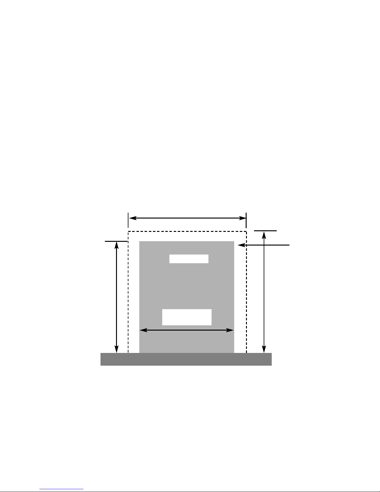
1.6 FIRE PLACE OPENING AND CHIMNEY CATCHMENT SPACE
The front opening of the fire place must be between 330 and 440mm wide, and
between 550 and 575mm high. If the opening exceeds these dimensions then a
surround must be constructed from suitable non-combustible material to produce a
correct size opening. Any surround must be suitably sealed to the fire place to
prevent leakage. See below in figure 1.
When installing into a brick built chimney, you must ensure that there is sufficient
depth to accomodate any debris which may fall from the chimney. This depth
must be sufficient to accomodate 12 litres of volumetric space.
Fire Opening
330mm Minimum
440mm Maximum
600mm
Minimum
460mm Minimum
Fig. 1
550mm Minimum
575mm Maximum
Minimum Flat
Sealing Area
7
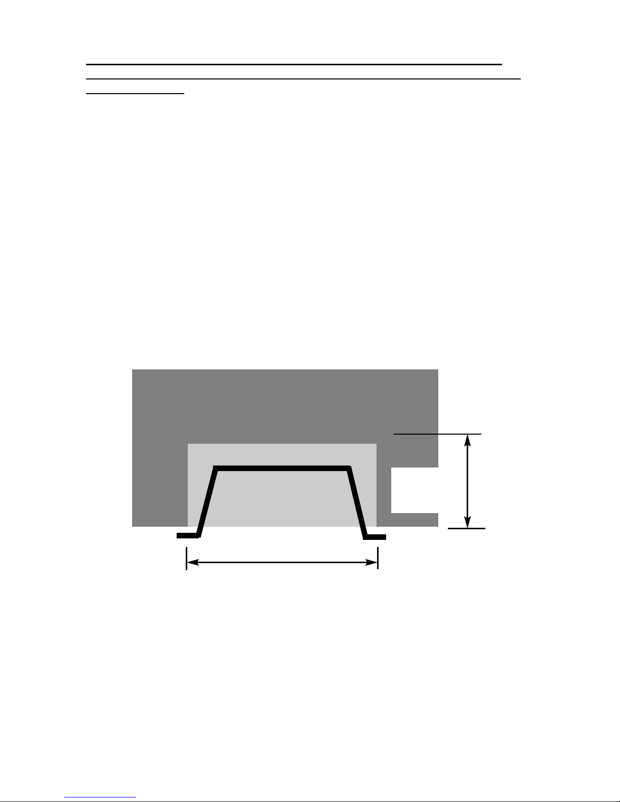
Table A - Installation Depth Requirements for a Global Corda Plus being
installed into a brick built chimney, requiring 12.0 litres of debris collection
volume (figure 2)
Opening Width (mm) Minimum Depth Required (mm)
330 (minimum opening width) 152
340 149
350 146
360 144
370 142
380 139
390 137
400 135
410 135
420 135
430 135
440 (maximum opening width)135
For example, if the appliance was to be fitted into a 400mm wide opening, the
depth required would be 135mm. See fig. 2 below for explanatory diagram.
Fig. 2
1.7 FITTING TO PRE-FABRICATED TWIN WALL METAL FLUE BOXES
The appliance may be fitted to twin wall metal flue boxes conforming to the
constructional requirements of BS 715 / BS EN 1856-2, (for example the Selkirk
LFE 175 box). The box must have a minimum flue diameter of 125mm internal
and minimum internal dimensions of 185mm deep by 580mm high by 400mm
wide. There are no maximum dimensional requirements for the box. The top face
of the box must be insulated with a minimum thickness of 50mm of
non-combustible mineral wool insulation or similar material. The flue box
must stand on a non-combustible base of minimum thickness 12mm.
8
Opening Width ( e.g. 400mm)
Depth Required
(e.g. 135mm
minimum)

1.8 HEARTHS
This appliance must only be installed on to a concrete or non-combustible hearth.
The hearth material must be a minimum thickness of 13mm with the top surface at
least 50mm above the floor. The hearth must be fitted symmetrically about the fire
opening and have a minimum width of 760mm and a minimum projection of
300mm forwards from the fire opening. EFC models required an increased hearth
projection of 320mm forwards of the fireplace opening.
1.9 FITTING TO PRE-CAST FLUE INSTALLATIONS
When installing this appliance into pre-cast flues, always ensure that the
spigot restrictor baffle has been removed. This is held in place on the spigot
by 2 screws. To install the fire box in to pre-cast flue starter blocks, there
must be at least 135mm from the mounting face of the fire to the rear of the
pre-cast flue starter block to allow sufficient space for debris collection. If this
dimension is less than 135mm then a fire surround with a deeper rebate to
increase the depth to at least 135mm from the mounting face of the fire. It is
important to consider this depth when choosing a fire surround as the thickness of
the fire surround must be sufficient to give a total depth of at least 135 mm to the
rear of the starter block, otherwise there will be insufficient depth. To increase
this depth the fire surround may be packed away from the wall using suitable noncombustible board, providing the installation is correctly sealed. If in doubt about
the suitability of the fire contact BFM Europe Ltd. for advice before proceeding.
It is important to ensure that the pre-cast flue is in good condition and is free from
extruded mortar or sealant from between the flue blocks.
This appliance has been tested for use in a pre-cast flue block complying with BS EN
1858. In accordance with BS EN 1858, pre-cast flues built with directly plastered faces
(front or rear) are not correctly installed as to ensure proper operation with any type of
gas fire. In some instances of this flue construction, temperature cracking of surface
plaster may occur through no fault of the appliance. An air gap or some form of
insulation material should be installed to prevent normal flue temperatures from
damaging wall surfaces.
1.10 SPILLAGE MONITORING SYSTEM
This appliance is fitted with an atmosphere sensing spillage monitoring system in
the form of an oxygen sensing pilot. This is designed to shut the fire off in the
event of a partial or complete blockage of the flue causing a build up of
combustion products in the room in which the fire is operated. The following are
important warnings relating to this spillage monitoring system :-
1) The spillage monitoring system must not be adjusted by the installer.
2) The spillage monitoring system must not be put out of operation.
3) When the spillage monitoring system is exchanged only a complete
original manufacturers part may be fitted.
9

SECTION 2
INSTALLATION OF FIRE
2.1 UNPACKING THE FIRE
Carefully lift the fire out of the carton. Remove the loose item packaging carefully
from the front of the appliance. Check the contents as listed :-
P
acking check list - manual control models
1 off Fire box / burner assembly
1 off Boxed ceramic base and 22 synthetic coals (2 small, 16 medium, 4 large)
1 off Loose items bag inc guarantee card and cable fixing kit
1 off Installation / user book (combined)
1 off Pebble set (if ordered as an optional extra) pack 2 of 2
Packing check list - remote control models
1 off Fire box / burner assembly
1 off Boxed ceramic base and 22 synthetic coals (2 small, 16 medium, 4 large)
1 off Loose items bag inc guarantee card, battery holder & cable fixing kit
1 off Installation / user book (combined)
1 off 9V battery
6 off 1.5V batteries
1 off Handset
1 off Pebble set (if ordered as an optional extra) pack 2 of 2
Packing check list - easy flame control models
1 off Fire box / burner assembly
1 off Boxed ceramic base and 22 synthetic coals (2 small, 16 medium, 4 large)
1 off Loose items bag inc guarantee card, battery holder & cable fixing kit
1 off Installation / user book (combined)
6 off 1.5V batteries
1 off Pebble set (if ordered as an optional extra) pack 2 of 2
2.2 INSTALLING THE FIRE BOX
Establish which type of flue you are intending to install the fire in to :-
225 x 225mm (9 inch x 9 inch) brick built chimneys
175mm (7 inch) diameter lined brick or stone flue, insulated pre-fabricated
metal flue box to BS 715 / BS EN 1856-2 or Pre-Cast Flue to BS EN 1858
When installing into 125mm (5 inch) diameter lined brick or stone flue, or
insulated pre-fabricated metal flue box to B.S. 715 and pre-cast flues the
restrictor baffle must not be fitted.
A spillage test must always be carried out to check satisfactory
clearance of flue products, regardless of the type of flue the
appliance is being fitted to.
10
For manual control models proceed as follows :-
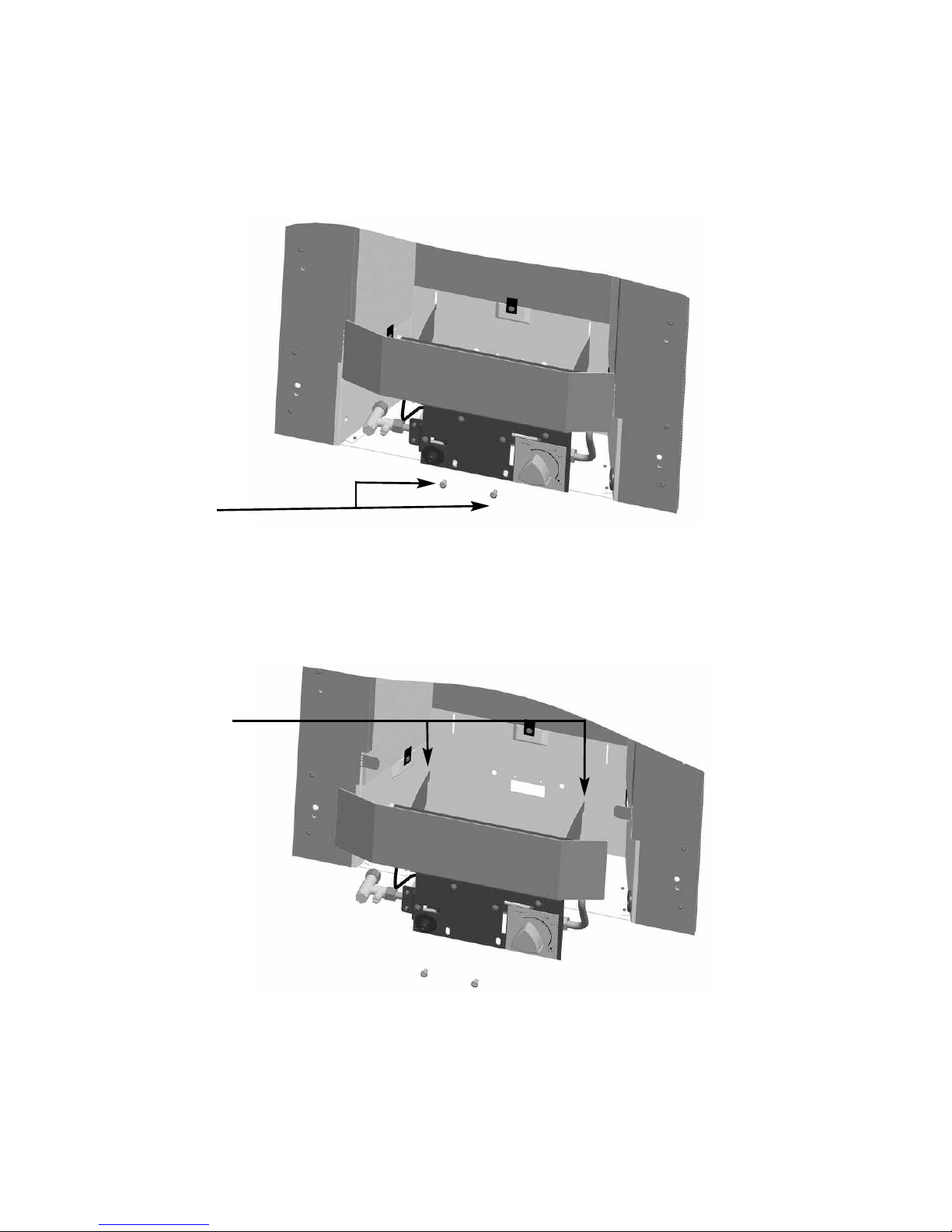
a) Remove the two screws at the bottom of the control panel. See fig. 3
below
Fig. 3
b) The base of the burner unit can now be lifted, lift the two retaining
tabs on the burner brackets from the back of the firebox, allowing
the burner to be removed. See fig. 4 below
Fig. 4
11
2 burner
retaining
screws
Retaining tabs
on burner

For remote and electronic fire control models proceed as follows :-
d) Remove the two screws at the bottom of the control panel, remove the
screw which retains the gas inlet elbow retaining bracket See fig. 5
below.
Fig. 5
e) The base of the burner unit can now be lifted, lift the two retaining
tabs on the burner brackets from the back of the firebox, allowing
the burner to be removed. See fig. 6 below
Fig. 6
f) Ensure that the hearth is protected from damage and carefully lift the
fire box into the fire opening, then slide it back into position. Check that
the fire box flange fits flush to the sealing face of the fire surround or
wall with no gaps present.
12
2 burner
retaining
screws
Retaining tabs
on burner
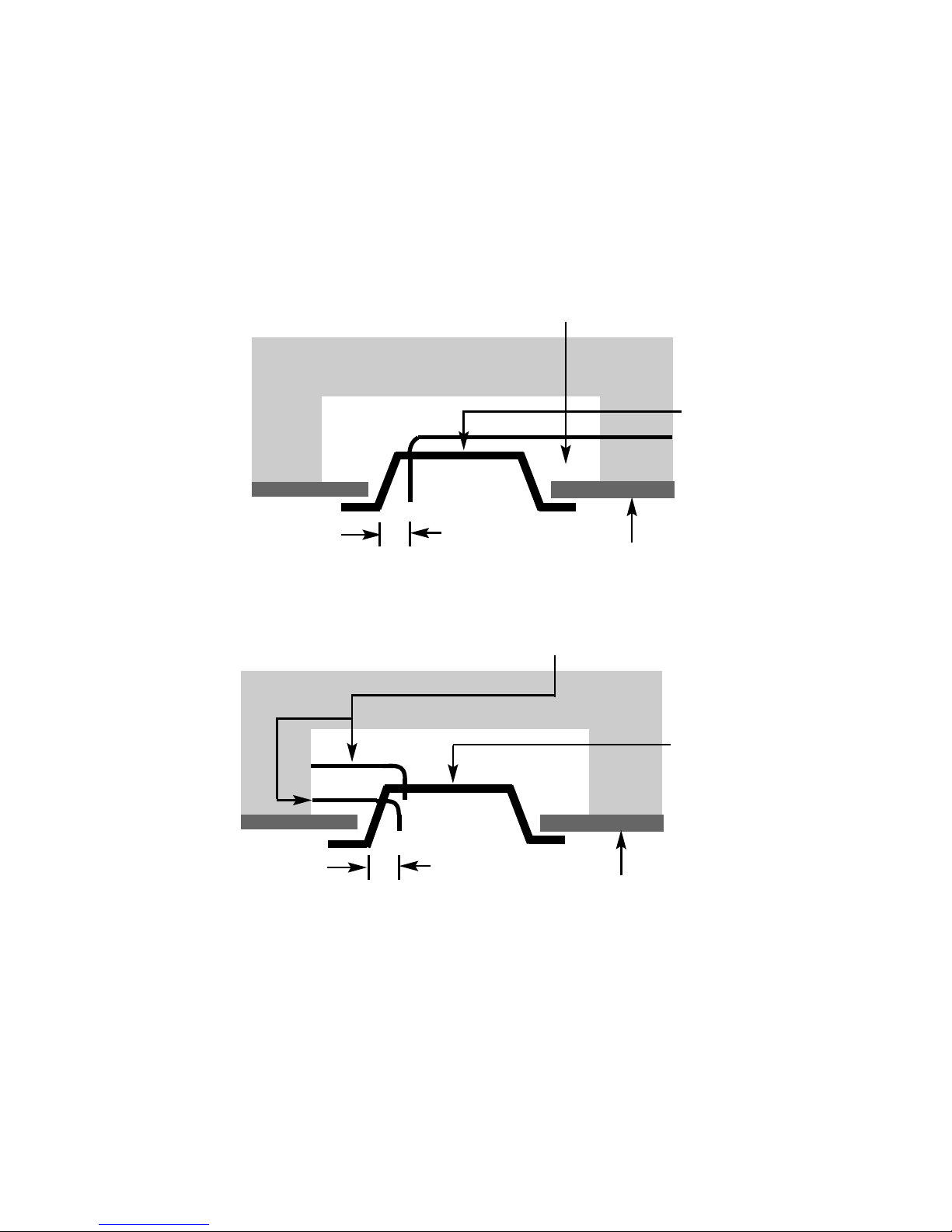
g) Whilst the fire box is still in position, decide which side the gas supply is
to enter the fire from. If concealed pipe work is required plan the pipe
run to enter the fire box through one of the openings in the sides or rear
of the fire box below the fuelbed support panel and connect to the
isolating / inlet elbow. The gas connection to the appliance should be
made to the isolating / inlet elbow using 8mm rigid tubing. There must
be no soldered joints within the firebox. See fig. 7 & 8 below for
suggested concealed pipe layouts.
Fig. 7 - R/H/S Gas Supply Route
Fig. 8 - L/H/S Gas Supply Routes
Note : Before breaking into the gas supply a tightness test should be carried
out to establish that the existing pipework is sound.
Carefully withdraw the fire box from the opening to enable the gas supply and fire
fixing to be completed.
13
Firebox
Approx.
40mm
Fireplace
Gas Supply
Firebox
Approx.
40mm
Fireplace
Gas supply options - L/H rear or L/H side

IMPORTANT : THE 45MM GROMMET SUPPLIED IN THE LOOSE ITEMS MUST BE USED
TO SEAL THE GAS INLET POINT UTILISED ON THE FIREBOX. FAILURE TO SEAL
THIS INLET POINT COULD RESULT IN FLAME REVERSAL AND DAMAGE TO THE
CONTROLS ON THE FIRE. BFM EUROPE ACCEPT NO RESPONSIBILITY FOR
DAMAGE TO THE FIRE AS A RESULT OF FAILURE TO FOLLOW THIS REQUIREMENT.
The preferred method of fixing which is suitable for almost all situations is
the cable fixing method which is described in the following section in detail.
To fit using the preferred cable method proceed as follows-
h) Mark out and drill 4 off No 14 (6mm) holes in the back face of the fire
opening in the positions shown below in figure 9
Fig. 9
Fit the wallplugs provided and screw the fixing eyes securely into the rear of the
fire opening.
i) Uncoil the two fire fixing cables and thread one end of each of the
cables through one of the two holes on each side of the flue outlet
shroud.
j) Position the fire carefully on the (protected) surface of the hearth and
reach into the fire opening. Thread each of the cables vertically
downwards through the pair of fixing eyes on the same side of the fire.
Thread the free end of the cables through the corresponding circular
hole on each side of the lower rear of the fire. Carefully slide the fire
box back into the fire opening and pull both cables tight.
k) Thread a tensioning screw over each of the cables and ensure that the
tensioning nut is screwed fully up against the hexagon shoulder of the
tensioning screw (this provides maximum travel for the tensioning nut).
l) Fit a screwed nipple on to each of the cables and pull hand tight up
against the tensioning screw, then secure each nipple with a flat
bladed screwdriver. See figure 10 overpage.
14
20mm
500mm
Fireplace Opening
100mm
250mm
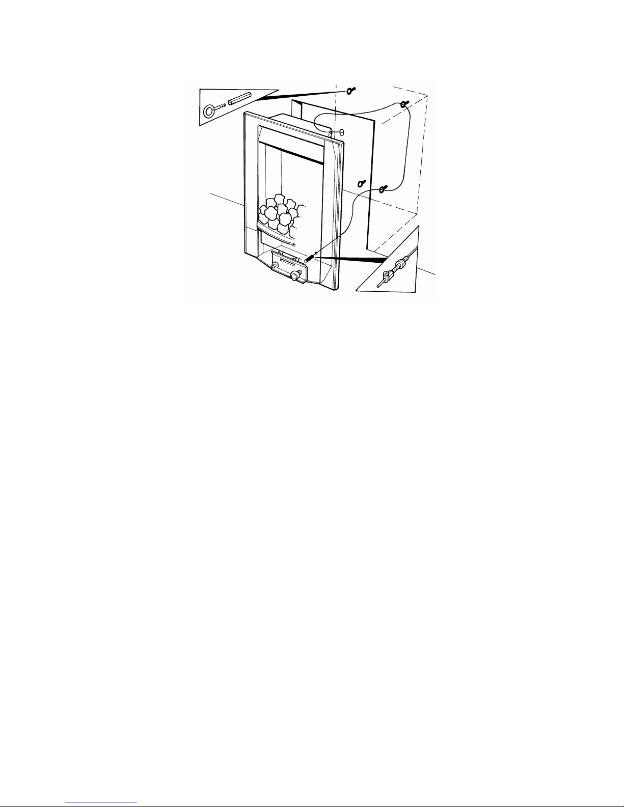
Fig. 10
m) Evenly tighten the tensioning nuts to tension both cables and pull the
fire snugly against the wall. Do not overtighten, it is only necessary to
pull the seal up against the sealing face of the wall, it does not need to
be compressed. Check that there are no gaps behind the seal.
n) With the fire securely in place, if a concealed gas connection has been
made through either of the access holes in the sides of the fire, the
holes should be closed around the pipe to prevent leakage of air
through the gap around the pipe.
o) Refit the burner. Fit the two retaining screws and check that the burner
is correctly locked into position.
p) Before making the final gas connection, thoroughly purge the gas
supply pipework to remove all foreign matter, otherwise serious
damage may be caused to the gas control valve on the fire.
15
 Loading...