

Global Fires Arana RC Installation And Maintenance Instructions Manual

Arana RC
COAL EFFECT GAS FIRE
Installation and Maintenance Instructions
Hand these instructions to the user
Model No’s GICC**RN is only for use on Natural Gas (G20) at a
supply pressure of 20 mbar in G.B. / I.E.
Model No’s GICC**RP is only for use on Propane Gas (G31) at a
supply pressure of 37 mbar in G.B. / I.E.
** denotes trim / fret variant

CONTENTS
Section 1 Information and Requirements PAGE
1.0 Appliance Information 3
1.1 Manual Handling Advice 4
1.2 Conditions of Installation 5
1.3 Flue and chimney suitability 5-6
1.4 Fireplace / surround suitability 6
1.5 Shelf position 6
1.6 Chimney inspection 7
1.7 Fire place opening / catchment space 8-9
1.8 Fitting to Metal Flue Boxes 10
1.9 Hearths 10
1.10 Spillage Monitoring System 10
1.11 Clearances to Combustible & Non-Combustible Surfaces 10
Section 2 Installation of Fire
2.1 Unpacking the fire 11
2.2 Installing the fire box 11-17
2.3 Gas tightness and inlet pressure 18
Section 3 Assembling Fuel Bed and Commissioning
3.1 Assembling the ceramics and fuel bed 19-22
3.2 Connecting the lithium battery pack 23
3.3 Fixing the Infrared eye in position 24
3.4 Lighting the appliance 25
3.5 Checking for clearance of combustion products 26
Section 4 Maintenance
4.1 Removal of the Burner Assembly 27
4.2 Removal of the Valve 28
4.3 Removal of the Pilot assembly 28
4.4 Removal of the batteries 28
The model no. of this appliance is as stated on the rating plate.
This product has been manufactured by :
BFM Europe Ltd,
Trentham Lakes,
Stoke-on-Trent,
ST4 4TJ
2
SECTION 1
INFORMATION AND REQUIREMENTS
1.0 APPLIANCE INFORMATION
Model GICC**RN GICC**RP
Gas Type G20 G31
Main injectors (2 off) Size 260 Size 85
Pilot Type Copreci Copreci
21100 / 162 21100 / 167
Max. Gross Heat Input : 6.9 kW 6.9 kW
Min. Gross Heat Input : 4.2 kW 4.2 kW
Cold Pressure : 20 +/- 1.0mbar 37 +/-1.0mbar
Ignition : 6V Battery Generator
Electrode Spark Gap : 4.5 Nominal
Weight : 17.5 kg
Minimum Combustible 200mm (from top of fire)
Shelf Height above fire
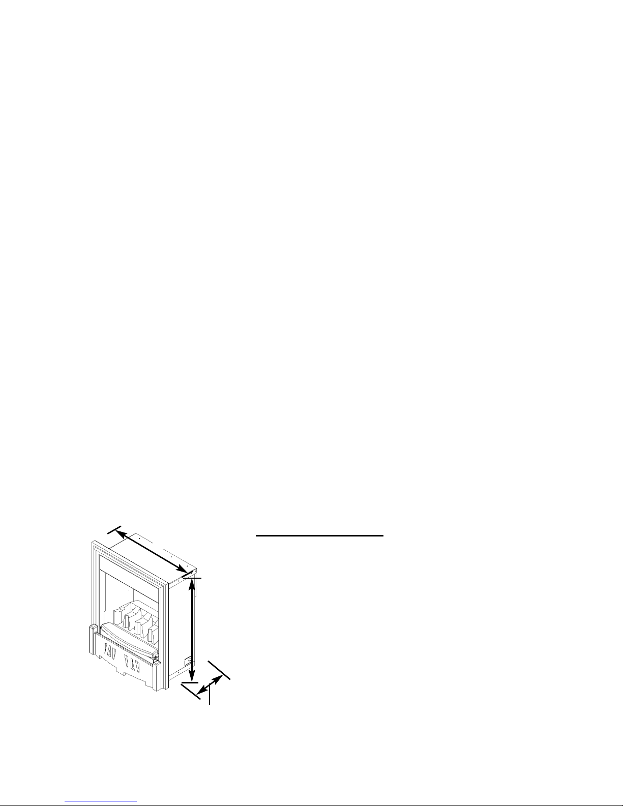
Fire box Dimensions (with trim fitted see fig. 1 below)
Width : (with standard trim) 485mm
Height : (with standard trim, no spacer) 595mm
Depth : (Into room) 75mm
Depth : (from mounting face to rear) 246mm (with baffle)
Depth : (from mounting face to rear) 227mm (without baffle)
Gas Connection 8mm Compression (Supplied with fire)
Fig. 1
3
595mm
485mm
246mm with baffle,
227mm without baffle
Efficiency Declaration
The efficiency of this appliance has been
measured as specified in BS 7977-1 : 2002 and
the result is 58%.
The gross calorific value of the fuel has been
used for this efficiency calculation. The test data
from which it has been calculated has been
certified by Advantica.
The efficiency value may be used in the UK
Governments Standard Assessment Procedure
(SAP) for energy rating of dwellings.

1.1 MANUAL HANDLING ADVICE
The following advice is offered when moving, manipulating and installing
this product :-
Always keep your back straight - bend using your legs
Avoid twisting at your waist - reposition your feet instead
Avoid upper body and top heavy bending - do not lean
forwards or sideways
Always grip the product with the palms of your hand - not
the tips of your fingers
Use the hand holes in the packaging that are provided
When lifting the product keep the load as close to your
body as possible (minimise the cantilever action and use
your clothing to provide additional grip)
Always use assistance if required
IF IN DOUBT REGARDING ANY MANUAL HANDLING OF
THIS PRODUCT - ASK !
4

INSTALLATION REQUIREMENTS
1.2 CONDITIONS OF INSTALLATION
In Great Britain :-
It is the law that all gas appliances are installed only by a GAS SAFE Registered
Installer in G.B. in accordance with these installation instructions and the Gas
Safety (Installation and Use) Regulations (current edition). Failure to install
appliances correctly could lead to prosecution. It is in your own interest and that
of safety to comply with the law. The installation must also be in accordance with
all relevant parts of the Local and National Building Regulations where
appropriate, the Building Regulations (Scotland Consolidation) issued by the
Scottish Development Department, and all applicable requirements of the following
British Standard Code of Practice.
1. B.S. 5871 Part 3 Installation of Decorative Fuel Effect Gas Fires
2. B.S. 6891 Installation of Gas Pipework
3. B.S. 5440 Parts 1 & 2 Installation of Flues and Ventilation
4. B.S. 1251 Open fire place components
5. B.S. 715 Metal flue pipes for gas appliances
6. B.S. 6461 Part 1 Installation of Chimneys and flues
7. I.S. 813 : 1996 Domestic Gas Installation (Republic of Ireland)
In Republic of Ireland :-
No purpose made additional ventilation is normally required for this
appliance, when installed in G.B. When Installing in I.E. please consult
document I.S. 813 : 1996 Domestic Gas Installation, which is issued by the
National Standards Authority of Ireland. If installing in Northern Ireland,
please consult local building regulations. Any purpose made ventilation
must be checked periodically to ensure that it is free from obstruction.
1.3 FLUE AND CHIMNEY SUITABILITY
This appliance is designed for use with conventional brick built or lined chimneys
and fabricated flues and metal flue boxes conforming to BS 715. All flues must
conform to the following minimum dimensions.
225mm x 225mm brick built chimneys (9 inch x 9 inch)
175mm (7 inch) diameter lined brick or stone flue, or insulated, pre fabricated
metal flue box to B.S. 715
125mm (5 inch) diameter lined brick or stone flue, or insulated, pre fabricated
metal flue box to B.S. 715
Before fitting to any flue of less than 175mm diameter or equivalent
cross-sectional area, the spigot restrictor baffle on the rear of the fire must be
removed
5
Safe clearance of products must always be checked by carrying out a smoke
match test as described. (see fig. 22 on page 26)
1.4 FIREPLACE / SURROUND SUITABILITY
The fire must only be installed on a hearth it must not be installed directly onto
carpet or other combustible floor materials.The fire is suitable for fitting to non-
combustible fire place surrounds and proprietary fire place surrounds with a
temperature rating of at least 150oc.
If a heating appliance is fitted directly against a wall without the use of a fire
surround or fire place all combustible material must be removed from behind
the trim. Soft wall coverings such as blown vinyl, wall paper etc. could be
affected by the rising hot air and scorching and/or discoloration may result.
Due consideration should be made to this when installing or decorating.
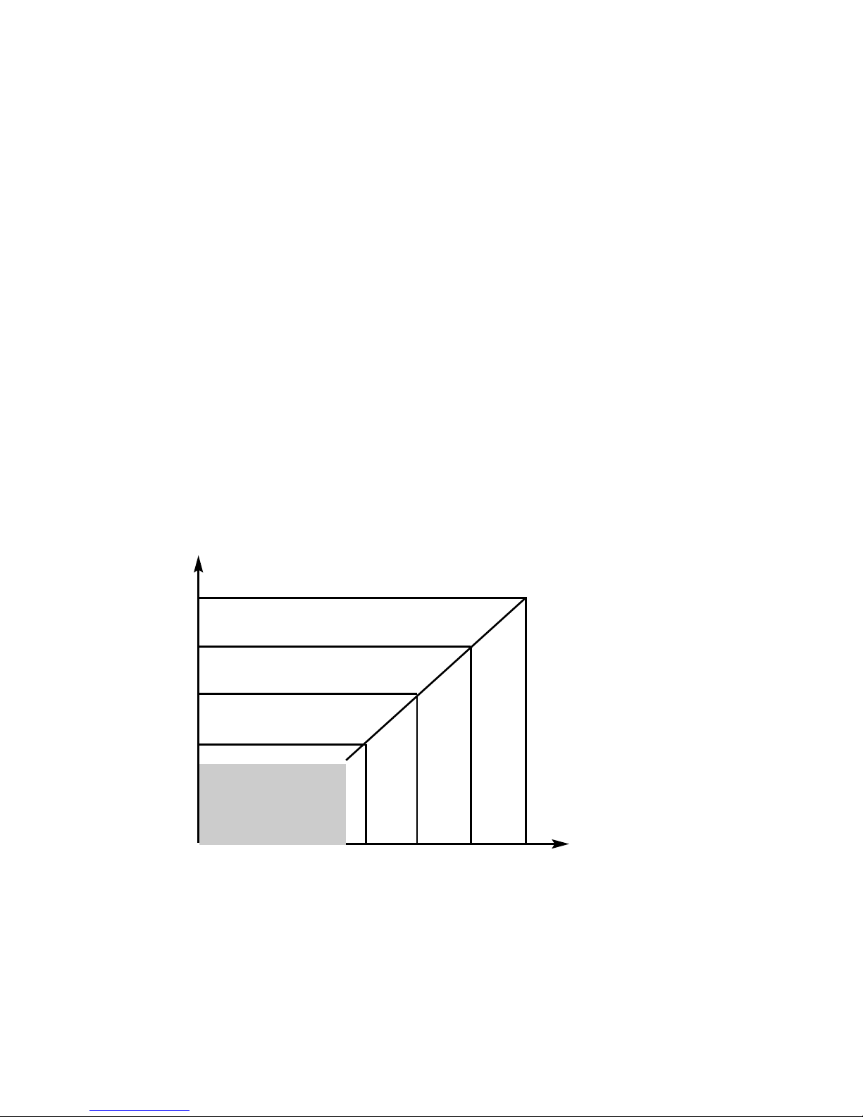
1.5 SHELF POSITION
The fire may be fitted below a combustible shelf providing there is a minimum
distance of 200mm above the top of the fire and the shelf does not project more
than 150mm. If the shelf overhangs more than 150mm the distance between the
fire and the shelf must be increased by 15mm for every 25mm of additional overhang over 150mm. See shelf graph (fig. 2 below)
Fig. 2
6
Fire must not be fitted if
the shelf height is less
than 200mm from the
top of the fire to the
underside of the shelf
830
815
800
795
150 175 200 225
Shelf Height
Above Hearth (mm)
Forward Shelf Projection (mm)

1.6 FLUE / CHIMNEY INSPECTION
Before commencing installation, a flue or chimney should be inspected to ensure
that all the following conditions are satisfied.
1. Check that the chimney / flue only serves one fire place and is clear of any
obstruction. Any dampers or register plates must be removed or locked in
the open position.
2. Brick/stone built chimneys or any chimney or flue which has been used for
an appliance burning fuel other than gas must be thoroughly swept. The
base of the chimney / flue must also be thoroughly cleared of debris etc.
3. Any under-floor air supply to the fire place must be completely sealed off.
4. Ensure that the inside of the chimney / flue is in good condition along it’s
length and check that there is no leakage of smoke through the structure
of the chimney during and after the smoke pellet test. With pre-cast flues
it is especially important to check the inside of the flue for extruded
cement / sealant protruding from the joints between the flue
blocks. If present, these should be removed by rodding the flue
before proceeding with the installation.
5. Using a smoke pellet, check that there is an up-draught in the
chimney / flue and that the smoke can be seen issuing from the
terminal / chimney pot outside.
There must be no leakage of smoke through the structure of
the chimney during or after the smoke pellet test and it is
important to check inside upstairs rooms adjacent to the chimney /
flue. Check the chimney pot / terminal and general condition of the
brickwork or masonry. If the chimney or flue is in poor condition or if
there is no up-draught do not proceed with the installation. If there is a
history of down-draught conditions with the chimney / flue, a tested and
certificated flue terminal or cowl suitable for the relevant flue type should
be considered.
6. A spillage test must always be carried out during commissioning of
the appliance.
7
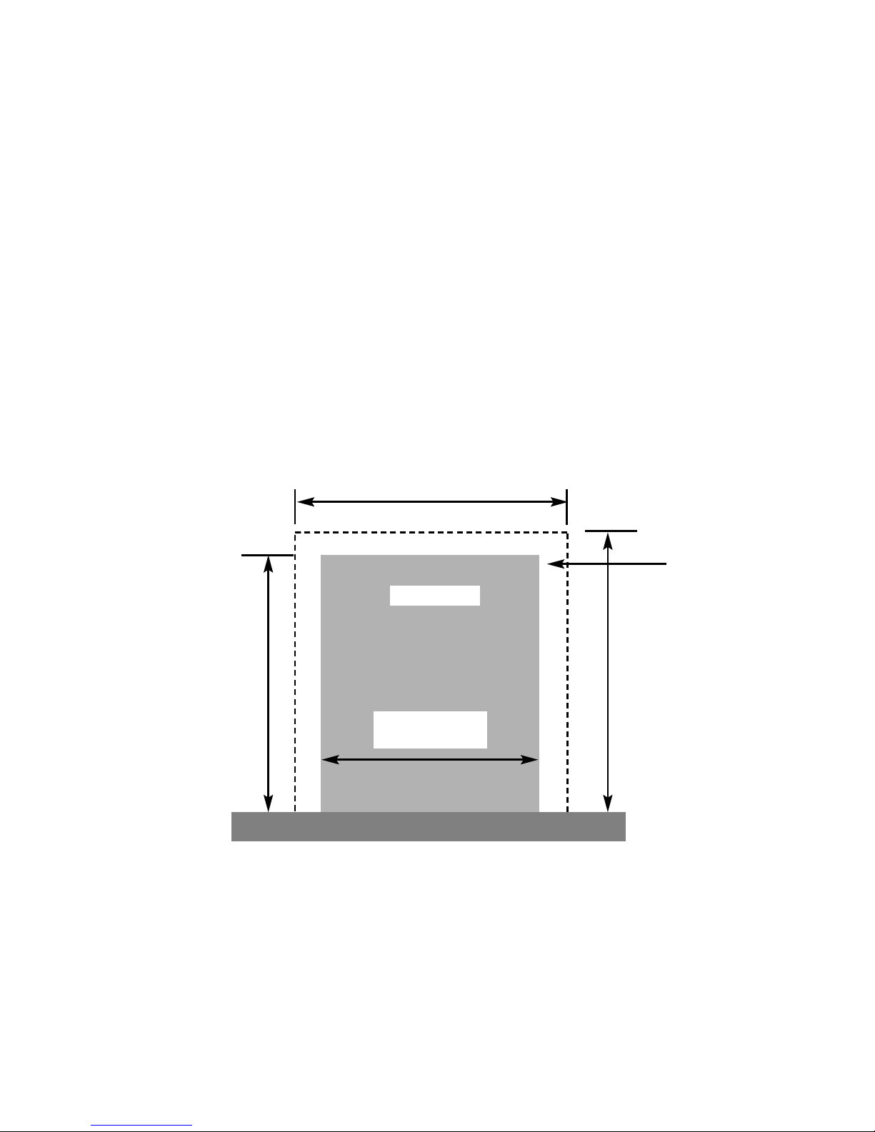
1.7 FIRE PLACE OPENING AND CHIMNEY CATCHMENT SPACE
The front opening of the fire place must be between 400 and 450 mm wide, and
between 550 and 570mm high.
Any chairbrick that is in place must be removed before proceeding with the
installation of this appliance.
If the opening exceeds these dimensions then a surround must be constructed
from suitable non-combustible material to produce a correct size opening.
Any surround must be suitably sealed to the fire place to prevent leakage. See
below in fig. 3
When installing into a brick built chimney, you must ensure that there is sufficient
depth to accomodate any debris which may fall from the chimney. This depth
must be sufficient to accomodate 12 litres of volumetric space.
Fire Opening
400mm Minimum
450mm Maximum
580mm
Minimum
470mm Minimum
Fig. 3
550mm Minimum
570mm Maximum
Minimum Flat
Sealing Area
8

Table A - Installation Depth Requirements for a Global Arana being installed
into a brick built chimney, requiring 12.0 litres of debris collection volume
(fig. 2)
Opening Width (mm) Minimum Depth Required (mm)
400 (minimum opening width) 298
410 292
420 285
430 280
440 273
450 (maximum opening width) 269
For example, if the appliance was to be fitted into a 400mm wide opening, the
depth required would be 298mm. See fig. 4 below for explanatory diagram.
Fig. 4
9
Opening Width ( e.g. 400mm)
Depth Required
(e.g. 298mm
minimum)
 Loading...