

Global Fire ZEOS-AD-S, ZEOS-AD-SH, ZEOS-AD-H, ZEOS-AD-SI, ZEOS-AD-SHI Instructions Manual
...
Instruction Manual V1 - 02/2014
FEATURES
ZEOS AD
Analogue Addressable Fire Detector
The ZEOS-AD series of Analogue Addressable Detectors
have been designed to be fully compatible with Global
Fire Equipment’s range of intelligent control panels,
JUNIOR and JUNO NET.
The ZEOS-AD series detectors must always be
connected to a compatible GFE Analogue Addressable
Fire Alarm Control Panel. The installation must be in
complian ce w ith the cont rol p anel’s syst em
installation manual.
GFE’s ZEOS-AD series is compliant to EN54-5 and EN547 and consists of: photoelectric smoke detectors, rate
of rise and fixed temperature/ heat detectors and
combined smoke and heat detectors. Optionally they
can be fitted with a short-circuit loop isolator.
WARNINGS
To prevent detector contamination and subsequent
invalidation of warranty, the smoke detector head
must remain with its protective cover fitted, until the
area covered is clean and dust free.
Detectors are intended for ceiling and wall mounting
and should always be installed in accordance with local
Fire Authority recomendations and regulations.
Do not install the detector head until the area is
thoroughly cleaned of construction debris, dusts, etc.
Please refer to the control panel’s installation manual
regarding the maximum number of detectors installed
on the same loop.
CAUTION: Do not attempt to disassemble the
detector. This is a sensitive device and is not intended
to be open for servicing by users. Opening the
detector head will void the warranty.
DO NOT PAINT DETECTOR HEAD
Dual LEDs for 360° visibility
Advanced detection and
communication protocols
Easy installation and maintenance
Sleek low-profile housing
Durable sensor head,
no need for replacement
SMD circuit board design.
High quality and reliability guaranteed
ORDER CODE
Loop Powered - 17V to 30V DC
450 uA max.
4 mA - Alarm LED Iluminated
According to EN54-5 and EN54-7
0.5-2.5 mm²
20 seconds max.
White / ABS
-10ºC to 50ºC / 95% RH Non-Condensing
100 mm (D) x 50 mm (H) inc. base / 144 g inc. base
TECHNICAL SPECIFICATIONS
SUPPLY VOLTAGE
CURRENT - QUIESCENT / SURGE
CURRENT - DEVICE IN ALARM
SENSITIVITY
CABLE SIZE
RESET/STAR-UP TIMES
COLOUR / CASE MATERIAL
OPER. TEMPERATURE / MAX. HUMIDITY
DIMENSIONS / WEIGHT
DESCRIPTION
Global Fire Equipment S.A. declares that this product is free from defects in materials and workmanship and it will repair or replace any
product or part thereof which proves to be defective in workmanship or materials during the life expectancy of the product. This period is
determined to be no longer than 10 years starting from the date of manufacture. Please visit Global Fire Equipment’s web site
(www.globalfire.pt) for a full description of Global Fire Equipment’s LIMITED WARRANTY, which, among other things, limits the duration of
warranties of merchantability and fitness for a particular purpose and excludes liability for consequential damages. Acceptance of order
and/ or original invoice which will become part of your sales agreement. Please contact Global Fire Equipment’s web site for details on how
to obtain a return Merchandise Authorization Number (RMA) before returning goods to the factory. Shipment must be prepaid and Global
Fire Equipment will repair or replace your returned detector.
LIFETIME WARRANTY
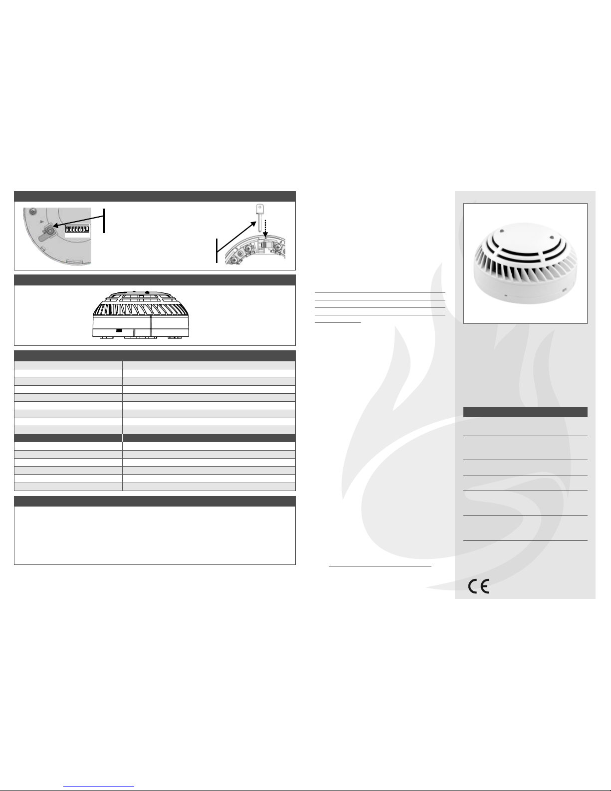
Detector Head
Detector Base
Alignment Marks
To lock detector remove pin available at
terminal 4 on the underside of the
sounder using a small screwdriver.
To unlock detector from its base push
unl ock key p rovide d th rough hol e
available on the base side wall as shown.
1 2
3
4
5
678
Address
DETECTOR BASE LOCK
MECHANICAL SPECIFICATION
Analogue Addressable Photoelectric Smoke Detector
Analogue Addressable Temperature/Heat Detector
Analogue Addressable Combined Smoke & Heat Detector
Analogue Addressable Photo. Smoke Detector inc. Isolator
Analogue Addressable Heat Detector inc. Isolator
Analogue Addr. Combined Smoke & Heat Detector w/ Isolator
ZEOS-AD-S
ZEOS-AD-H
ZEOS-AD-SH
ZEOS-AD-SI
ZEOS-AD-HI
ZEOS-AD-SHI
Made in Portugal-EU
GLOBAL FIRE EQUIPMENT S.A.
Sítio dos Barrabés, Armazém Nave Y, Caixa Postal 908-Z, 8150-016 São Brás de Alportel - PORTUGAL
Tel: +351 289 896 560 • Sales: sales@globalfire.pt • Technical Support: techs@globalfire.pt • www.globalfire.pt
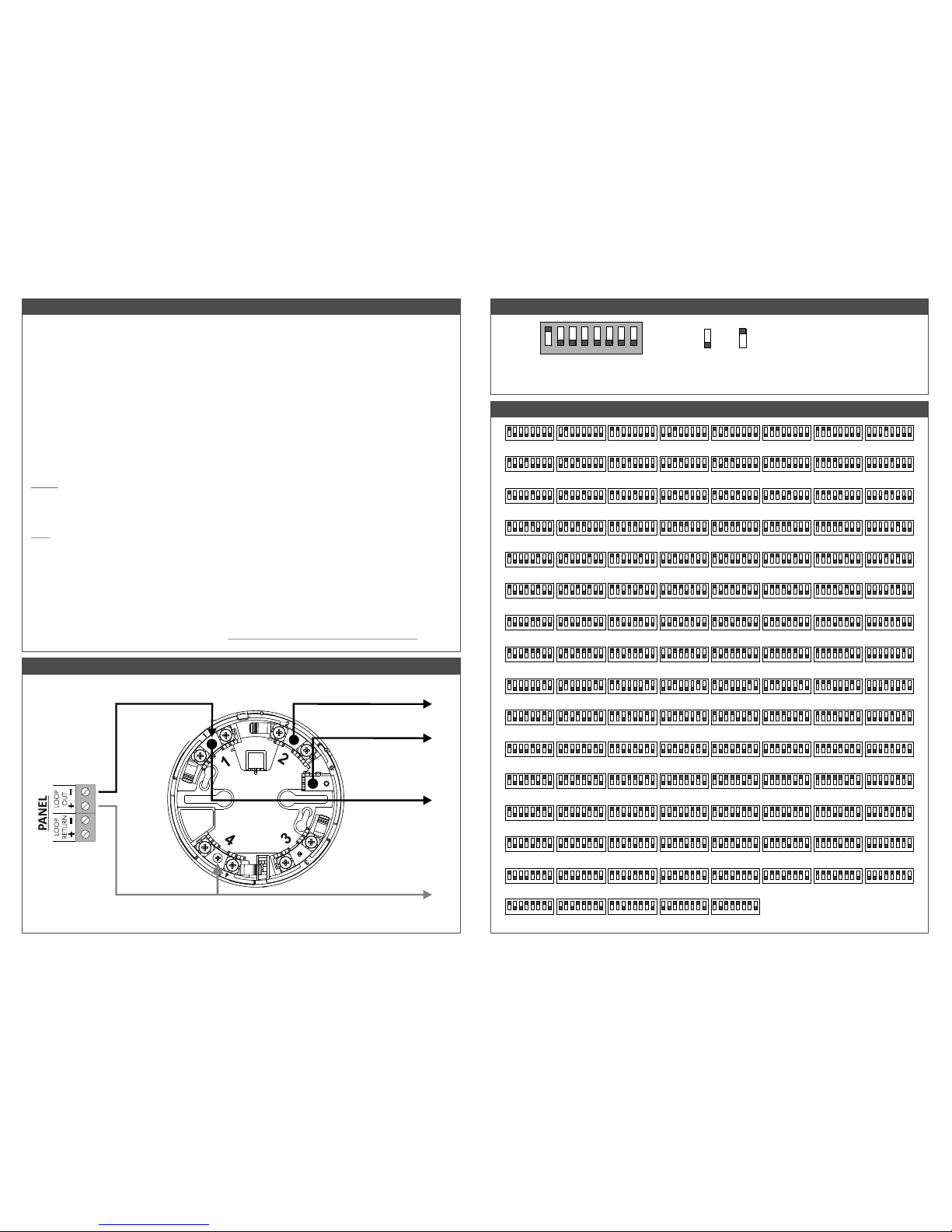
D.I.L. SWITCHES CONFIGURATION
INSTALLING THE BASE
To ensure proper fit of the detector head to the base, all wires should be properly dressed at installation by positioning
all wires flat against terminals and fastening the wires away from connector terminals. The detector base can be
mounted directly onto most standard electrical junction boxes.
INSTALLING THE HEAD
Set the desired address via D.I.L. switch on the back of the detector. Please refer to D.I.L. Switch Configuration and
Address Settings sections. Allign detector components using provided allignment marks on both the head and base.
Allign detector mark and short allignment mark on base. Fit the detector head onto the base and twist clockwise to
secure it. After all detectors are installed, apply power to the control unit and activate the detection loop. Test the
detectors as described below.
TESTING
All remote signalling systems, releasing devices and extinguishing systems should be disconnected during the test
period and reconnected at the conclusion of testing.
SMOKE: Allow smoke from a cotton wick or test smoke aerosol to enter the detector’s smoke chamber for at least 10
seconds. When sufficient smoke has entered, the detector will signal an alarm. This will be indicated by the illumination
of the 2 RED LEDs provided. Make sure to clear smoke out of the chamber before resetting in order to keep the detector
at its current sensitivity setting.
HEAT: The detector to be tested should be subject to a flow of warm air at a temperature of between 65ºC and 80ºC.
This requirement can be met by some domestic hair dryers. Switch on the warm airflow and check that the temperature
is correct and stable. From a distance of several cms, direct the airflow at the guard protecting the thermistor. The
detector should alarm within 60 seconds. Upon alarm immediately remove the heat source and check that the RED
LEDs of the detector are illuminated. If a detector fails to activate within 60 seconds, confirm connections and
programming. If necessary replace unit. Note: After testing, check that the system is returned to normal operation.
Notify the appropriate authorities that the testing procedure has been completed and the system is active again.
MAINTENANCE
The recommended minimum requirement for detector maintenance consists of annual cleaning of dust from the
detector head using a low power vacuum cleaner. >> DO NOT ATTEMPT TO DISASSEMBLE THE DETECTOR
1
2
3
4 5 6 7 8
1
2
3
4 5 6 7 8
1
2
3
4 5 6 7 8
1
2
3
4 5 6 7 8
1
2
3
4 5 6 7 8
1
2
3
4 5 6 7 8
01 02 03 04 05 06 07 08
1
2
3
4 5 6 7 8
1
2
3
4 5 6 7 8
1
2
3
4 5 6 7 8
1
2
3
4 5 6 7 8
1
2
3
4 5 6 7 8
1
2
3
4 5 6 7 8
1
2
3
4 5 6 7 8
1
2
3
4 5 6 7 8
1
2
3
4 5 6 7 8
1
2
3
4 5 6 7 8
09 10 11 12 13 14 15 16
1
2
3
4 5 6 7 8
1
2
3
4 5 6 7 8
1
2
3
4 5 6 7 8
1
2
3
4 5 6 7 8
1
2
3
4 5 6 7 8
1
2
3
4 5 6 7 8
1
2
3
4 5 6 7 8
1
2
3
4 5 6 7 8
17 18 19 20 21 22 23 24
1
2
3
4 5 6 7 8
1
2
3
4 5 6 7 8
1
2
3
4 5 6 7 8
1
2
3
4 5 6 7 8
1
2
3
4 5 6 7 8
1
2
3
4 5 6 7 8
1
2
3
4 5 6 7 8
1
2
3
4 5 6 7 8
25 26 27 28 29 30 31 32
1
2
3
4 5 6 7 8
1
2
3
4 5 6 7 8
1
2
3
4 5 6 7 8
1
2
3
4 5 6 7 8
1
2
3
4 5 6 7 8
1
2
3
4 5 6 7 8
1
2
3
4 5 6 7 8
1
2
3
4 5 6 7 8
33 34 35 36 37 38 39 40
1
2
3
4 5 6 7 8
1
2
3
4 5 6 7 8
1
2
3
4 5 6 7 8
1
2
3
4 5 6 7 8
1
2
3
4 5 6 7 8
1
2
3
4 5 6 7 8
1
2
3
4 5 6 7 8
1
2
3
4 5 6 7 8
41 42 43 44 45 46 47 48
1
2
3
4 5 6 7 8
1
2
3
4 5 6 7 8
1
2
3
4 5 6 7 8
1
2
3
4 5 6 7 8
1
2
3
4 5 6 7 8
1
2
3
4 5 6 7 8
1
2
3
4 5 6 7 8
49 50 51 52 53 54 55
1
2
3
4 5 6 7 8
56
1
2
3
4 5 6 7 8
1
2
3
4 5 6 7 8
1
2
3
4 5 6 7 8
1
2
3
4 5 6 7 8
1
2
3
4 5 6 7 8
1
2
3
4 5 6 7 8
1
2
3
4 5 6 7 8
57 58 59 60 61 62 63
1
2
3
4 5 6 7 8
64
1
2
3
4 5 6 7 8
1
2
3
4 5 6 7 8
1
2
3
4 5 6 7 8
1
2
3
4 5 6 7 8
1
2
3
4 5 6 7 8
1
2
3
4 5 6 7 8
1
2
3
4 5 6 7 8
1
2
3
4 5 6 7 8
65 66 67 68 69 70 71 72
1
2
3
4 5 6 7 8
1
2
3
4 5 6 7 8
1
2
3
4 5 6 7 8
1
2
3
4 5 6 7 8
1
2
3
4 5 6 7 8
1
2
3
4 5 6 7 8
1
2
3
4 5 6 7 8
1
2
3
4 5 6 7 8
73 74 75 76 77 78 79 80
1
2
3
4 5 6 7 8
1
2
3
4 5 6 7 8
1
2
3
4 5 6 7 8
1
2
3
4 5 6 7 8
1
2
3
4 5 6 7 8
1
2
3
4 5 6 7 8
1
2
3
4 5 6 7 8
1
2
3
4 5 6 7 8
81 82 83 84 85 86 87 88
1
2
3
4 5 6 7 8
1
2
3
4 5 6 7 8
1
2
3
4 5 6 7 8
1
2
3
4 5 6 7 8
1
2
3
4 5 6 7 8
1
2
3
4 5 6 7 8
1
2
3
4 5 6 7 8
1
2
3
4 5 6 7 8
89 90 91 92 93 94 95 96
1
2
3
4 5 6 7 8
1
2
3
4 5 6 7 8
1
2
3
4 5 6 7 8
1
2
3
4 5 6 7 8
1
2
3
4 5 6 7 8
1
2
3
4 5 6 7 8
1
2
3
4 5 6 7 8
1
2
3
4 5 6 7 8
97 98 99 100 101 102 103 104
1
2
3
4 5 6 7 8
1
2
3
4 5 6 7 8
1
2
3
4 5 6 7 8
1
2
3
4 5 6 7 8
1
2
3
4 5 6 7 8
1
2
3
4 5 6 7 8
1
2
3
4 5 6 7 8
1
2
3
4 5 6 7 8
105 106 107 108 109 110 111 112
1
2
3
4 5 6 7 8
1
2
3
4 5 6 7 8
1
2
3
4 5 6 7 8
1
2
3
4 5 6 7 8
1
2
3
4 5 6 7 8
1
2
3
4 5 6 7 8
1
2
3
4 5 6 7 8
1
2
3
4 5 6 7 8
113 114 115 116 117 118 119 120
1
2
3
4 5 6 7 8
1
2
3
4 5 6 7 8
1
2
3
4 5 6 7 8
1
2
3
4 5 6 7 8
1
2
3
4 5 6 7 8
121 122 123 124 125
ADDRESS SETTINGS
4 on =8
5 on =16
6 on =32
7 on = 64
Address Switches binary weights
1 on =1
2 on =2
3 on =4
Switches 1-7
used to configure the module’s address
Switch 8
Not used
1 2
3
4
5
678
ON
OFF
ON
OFF
-Loop IN/ OUT
- REMOTE LED INDICATOR
+Loop IN/ OUT
-Loop IN/ OUT
SCREEN
INSTALLATION
DETECTOR BASE - LOOP CONNECTIONS
Note: Positive terminal of remote indicator should be connected to terminal 4 (+ Loop IN/ OUT)
To next device
in loop or return
to panel
 Loading...