

Global Fire ORION 4, ORION 2, ORION 8 Installation, Operation And Maintenance Manual

Manufacturers of Fire Detection Equipment
www.globalfire.pt
INSTALLATION, OPERATION AND MAINTENANCE MANUAL - 10/2011
ORION - 2, 4, 8 ZONE FIRE ALARM CONTROL PANEL
INSTALLATION, OPERATION AND MAINTENANCE MANUAL
Version - 10/2011
ORION
2, 4, 8 Zone Fire Alarm Control Panel

Manufacturers of Fire Detection Equipment
www.globalfire.pt
INSTALLATION, OPERATION AND MAINTENANCE MANUAL - 10/2011
ORION - 2, 4, 8 ZONE FIRE ALARM CONTROL PANEL
EN54 INFORMATION
In accordance with EN 54-2 clause 13.7, the maximum number of sensors and/or manual call points in this
panel, will not exceed 512 units.
The Fire Detection Control Panel complies with the requirements of EN 54 -2 and EN 54- 4. In addition to the
requirements of the above mentioned standard, the unit conforms to the following optional functions:
EN 54-2 Clause 7.11 Controls Delays for activation of outputs
EN 54-2 Clause 8.3 Fault signals from points
1

Manufacturers of Fire Detection Equipment
www.globalfire.pt
INSTALLATION, OPERATION AND MAINTENANCE MANUAL - 10/2011
ORION - 2, 4, 8 ZONE FIRE ALARM CONTROL PANEL
Overview
Features
Optional Interfaces
The ORION is a 2, 4 and 8 Zone microprocessor controlled conventional Fire Alarm Control Panel with all the
functions necessary to control small and medium size fire detection installations.
Two, four and eight zone non-expandable control panels
Up to 32 conventional smoke and/or heat detectors per zone
Active End of Line monitoring
Programmable non-latching zones
Programmable delay timer for sounder and relay activation. Maximum 10 minutes
(Day/Night Function)
Delayed operation selectable for each zone
Zone coincidence programmable for adjacent zones
Two Access Levels. Selectable by fixed code entry
One man test
Supervised auxiliary 24 volt output
2 supervised/ monitored sounder circuits
3 Remote inputs for Class change, Day/Night Operation and remote reset
2 Relay outputs for fire and fault indications. Unmonitored
Power supply 1,7A @ 28.5V DC nominal
EN54 part 2 and 4 compliant
Repeater output. To be used with our standard data loop interfaces, Rs485, Fibre Optics and TCP/IP (LAN)
Multiplexed output for LEDS and additional relay outputs per zone (Max 8 zones)
Analogue interface cards available to interface Orion panel to our range of addressable panels, JUNO-
NET and JUNIOR. (P/N: ADLI)
2
EN54 Information
Page Nº
2 3 -
4 5 6 7 8 -
1 -
Overview/ Features
Important Safety Notes / Mounting the Panel
Cable Types / Detection Zone Wiring
Sounder Circuit Wiring / Auxiliary Input Wiring
Outputs / Optional additional Outputs
Connecting the Panel
Commissioning
9 -
12 13 14 17 18 19 -
Testing Field Equipment
Operating & Programming the Panel
Programmable Options
Delay Settings & Non-Latching Zones
The Panel Buttons
Troubleshooting - Fault Indications
Standby Battery Calculation
Technical Specifications
10 -
Important Safety Notes
competent person.
This equipment must have an Earth Connection.
A basic knowledge and training in the installation of Fire Detection systems is assumed.
The Fire Detection system should be designed by a suitably qualified person with reference to the Local
Regulations and Guidance from the fire Officer where applicable.
This equipment must only be installed and maintained by a suitably qualified and technically
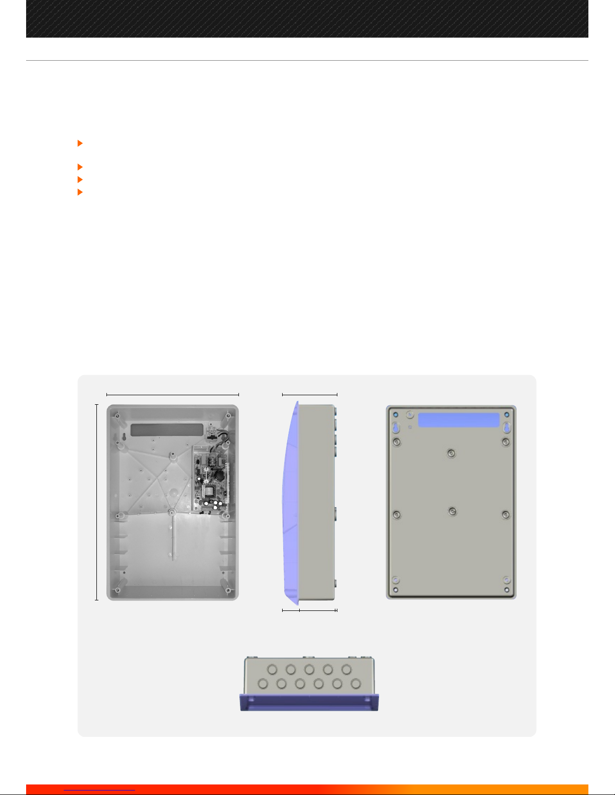
Mounting the Panel
The ORION housing is designed for either surface or semi-recessed mounting. Cable entry points are
provided at the top and back of the housing. Do not drill additional holes as cables could then interfere with
the PCB or standby battery position. Maintain separation between the incoming 230 volt mains cable and
the low voltage detector and sounder cabling.
The panel should be fixed to the wall using the 4 mounting holes provided and No 8-10 countersunk screws.
Any dust created during the fixing process must be kept out of the control panel and care must be taken not
to damage any wiring or components.
106 mm
33
70
3
273 mm
403 mm
VIEW FROM SIDE
VIEW FROM TOP
INSIDE VIEW VIEW FROM REAR
3
Manufacturers of Fire Detection Equipment
www.globalfire.pt
INSTALLATION, OPERATION AND MAINTENANCE MANUAL - 10/2011
ORION - 2, 4, 8 ZONE FIRE ALARM CONTROL PANEL
Cable Types
Detection Zone Wiring
System wiring should be installed in accordance with National Standards and wiring regulations.
To protect against electrical interference we recommend the use of screened cables throughout the system.
Separate cables should be used for sounder and detection circuits, the use of multi-core cables to carry
sounder circuits and detector circuits is not recommended. The cable screens should be terminated and
connected to Earth at the panel only.
Maximum cross section of cables to use is 2.5mm² to avoid damaging the terminals in the control panel.
Mains wiring should be 3 core 1mm² to 2.5mm² fed from an isolating fused spur, fused at 3A. This should be
secure from unauthorized operation and be marked “Fire Alarm Do Not Switch Off” The mains supply must be
exclusive to the fire panel.
Two, four or eight zones are available for detection device wiring. Each zone has capacity for up to 32 smoke /
heat detectors and an unlimited number of manual call points. This may be restricted by local regulations.
An active end of line module (capacitor) is supplied for each zone, as part of the monitoring circuit. This must
be fitted to the last device of each Zone. If a detection zone is unused the end of line module must be
connected at the panel, if is not fitted, a fault will be indicated for that zone.
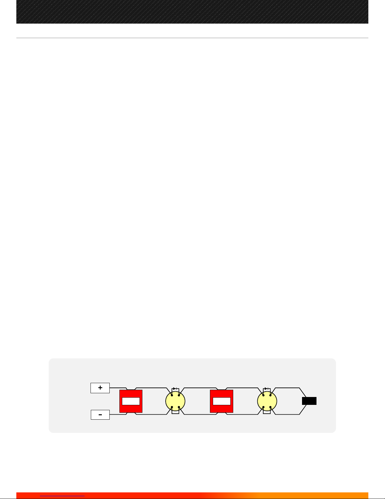
A typical detector circuit wiring layout is shown below. Please consult the device manufacturer's instruction
manual for detailed information.
If manual call points are wired on the same circuit as detectors then in order to comply with the requirements
of BS5839 with respect to head removal monitoring, detector bases should have a Schottky diode fitted
which permits manual call points after a removed detector to continue to operate normally. (see diagram).
Manual call points should have a maximum internal resistance of (470-680) ohms in Alarm.
The wiring for each detector zone should be terminated in the relevant terminal blocks at the control panel
and the cable screens connected to earth.
MANUAL
CALL
POINT
SMOKE
OR HEAT
DETECTOR
SMOKE
OR HEAT
DETECTOR
MANUAL
CALL
POINT
END OF LINE
CAPACITOR
PANEL
DETECTOR
CIRCUIT
TERMINALS
4
Manufacturers of Fire Detection Equipment
www.globalfire.pt
INSTALLATION, OPERATION AND MAINTENANCE MANUAL - 10/2011
ORION - 2, 4, 8 ZONE FIRE ALARM CONTROL PANEL
Sounder Circuit Wiring
Auxiliary Input Wiring
There are two conventional sounder circuits available on the Orion. The maximum current available for
sounders is (500 mA) per circuit. All sounders must be polarized, non-polarized sounders will indicate a
fault on the sounder circuit.
An end of line resistor (10 K Ohm) which is supplied with the panel, must be inserted in the last sounder for
cable monitoring. If a sounder circuit is not used, the EOL resistor should be fitted in the control panel
sounder output.
The sounder circuits are protected against short circuits, the electronic fuse will reset when the short
circuit is removed and the control panel is reset.
The wiring for each sounder circuit should be terminated in their respective terminals and the cable
screens connected to earth.
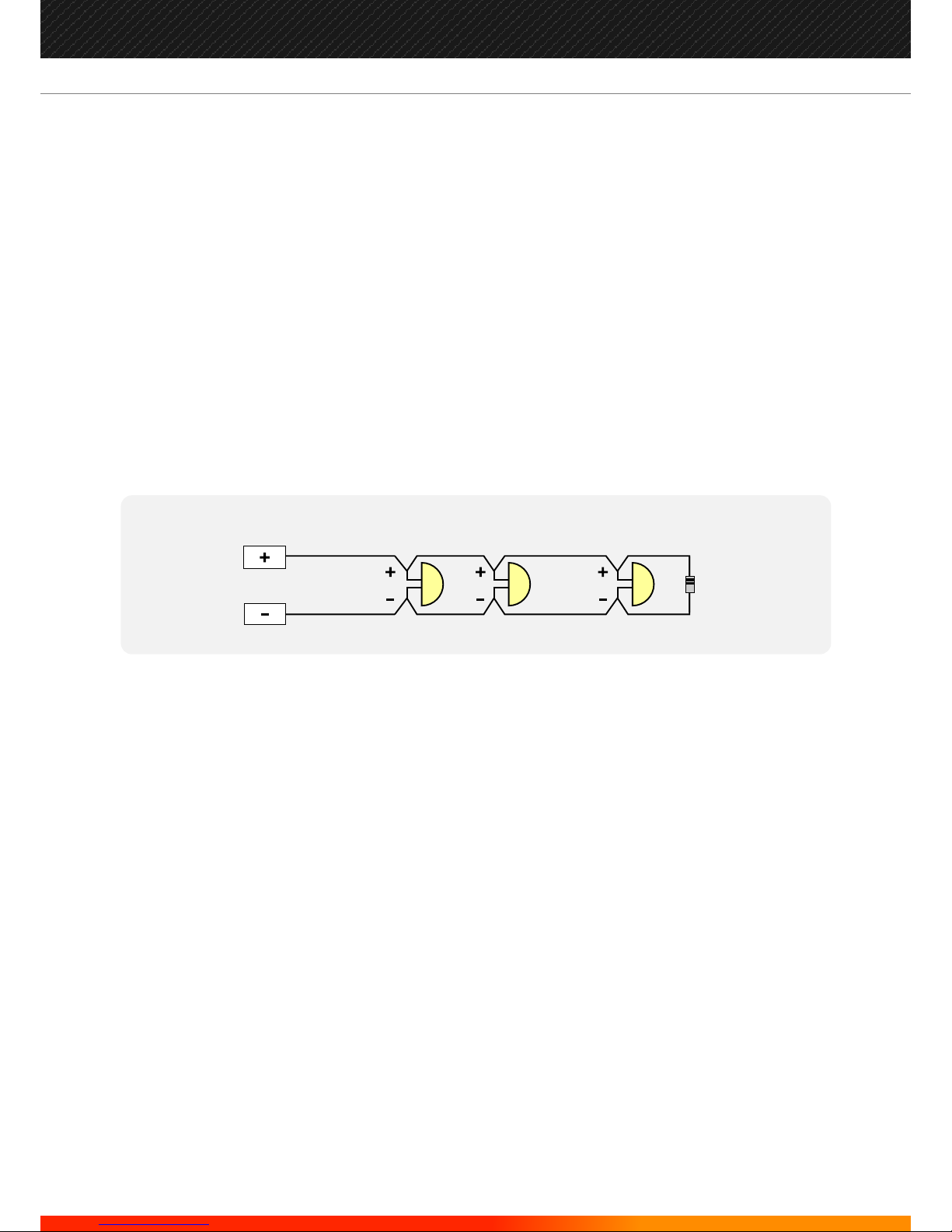
Typical sounder circuit wiring diagram:
There are three remote activation inputs. All remote inputs are activated using a voltage free dry contact
like a relay.
Reset: The closure of a contact at this input will cause the panel to reset. In order to reapply a reset to the
panel, contact has to be released and reapplied. Pulse action.
Auxiliary Inputs 1 and 2 are non-Latching inputs with the following functions:
1º Class Change/Evacuate: Activates sounders immediately when 0V is applied via a voltage free
contact. Sounders active LED is illuminated, Sounders continue to operate until the input is removed.
Pressing the Silence button will stop the sounders.
2º Remote Day/Night Operation: Allows switching between Day and Night operation from a remote
location or with time clock etc.
In the Active state (contact closed), programmed delays are active (Day operation) and the delays active
LED is illuminated.
In the Normal state, programmed delays are ignored (Night operation) and the Delays active LED is
extinguished.
The wiring for each auxiliary input should be terminated in their respective terminals and the cable
screens connected to earth.
POLARIZED
SOUNDER
END OF LINE
RESISTOR
10K Ohm
POLARIZED
SOUNDER
POLARIZED
SOUNDER
SOUNDER
CIRCUIT
TERMINALS
5
Manufacturers of Fire Detection Equipment
www.globalfire.pt
INSTALLATION, OPERATION AND MAINTENANCE MANUAL - 10/2011
ORION - 2, 4, 8 ZONE FIRE ALARM CONTROL PANEL

Outputs
Optional additional Outputs
Auxiliary Power 28V DC max 300 mA, short circuit protected, supervised. The output is protected
against short circuit by an electronic fuse which resets when the fault is cleared and
the panel is reset.
Relay Contact Fire Provide Fire signal to external devices.
Relay contact changeover 30V /1A max resistive.
Active until Reset.
Relay Contact Fault Provide Fault signal to external devices.
Relay contact NC 30V / 1A max resistive.
Also Active for microprocessor fault.
Active until Reset and all faults are cleared.
Relay contact will open when any fault is present on the system.
The wiring for each output should be terminated in their respective terminals and the cable screens
connected to earth.
Repeater Output Multiplexed Fire and Fault indication per zone. Remote system command.
Interface cards available for RS-485, Fibre Optics and TCP/IP (LAN) connection.
Zone Relay Outputs Additional relay per zone follows zone status. 8 zones max.
Zone LED outputs For remote installation. Multiplexed LED boards can reflect status of panel, i.e. Fire,
Fault, Test, Disabled, etc. and/ or zone status.
Analogue Detection Loop Interface card (ADLI) available for direct interface of Orion to the analogue detector
loop of any of our analogue addressable panels, Junior or Juno Net, allowing the Orion to be used as an
effective and practical Shop Monitoring Unit.
NOTE: Sounders and Alarm outputs only become active at the end of any programmed delay period. If
during the delay period, the DELAYS ACTIVE button is pressed at access level 1 (no code entry required), delay
expires and sounders activate immediately
6
Manufacturers of Fire Detection Equipment
www.globalfire.pt
INSTALLATION, OPERATION AND MAINTENANCE MANUAL - 10/2011
ORION - 2, 4, 8 ZONE FIRE ALARM CONTROL PANEL
 Loading...