

Global Fire JUNO NET Installation Manual

Manufacturers of Fire Detection Equipment
INSTALLATION & COMMISSIONING MANUAL REVISION 4.0 05/2013
JUNO NET - NETWORKABLE ADRESSABLE PANEL
globalfire.pt
INSTALLATION MANUAL
version 4.0 - 05/2013
JUNO NET
NETWORKABLE ADDRESSABLE PANEL

2
OVERVIEW
Introduction ....................................................................................................................................................................................... 7
EN-54 Information and Key Features......................................................................................................................................... 7
Typical System Schematic.............................................................................................................................................................. 9
Typical System Block Diagram......................................................................................................................................................10
Power Requirements........................................................................................................................................................................11
Battery Requirements......................................................................................................................................................................12
Identifying Components.................................................................................................................................................................13
Recommended Cables.....................................................................................................................................................................19
. . . Analogue Loops, Conventional Sounders and Data Loops......................................................................................19
Limitations............................................................................................................................................................................................19
Definitions.............................................................................................................................................................................................20
INSTALLATION
Introduction....................................................................................................................................................................................... 22
Main Panel........................................................................................................................................................................................... 22
. . . Mains Power Connection......................................................................................................................................................22
. . . Other Main Panel connections............................................................................................................................................22
. . . Integrated Sub-panels............................................................................................................................................................23
Repeaters............................................................................................................................................................................................ 25
Mains Power Connection..................................................................................................................................................... 25
Integrated Sub-panels........................................................................................................................................................... 25
Standard Sub-panels....................................................................................................................................................................... 26
Data Loops.......................................................................................................................................................................................... 28
. . . Main Panel Rs485.....................................................................................................................................................................28
. . . Data Loop Interface Configuration....................................................................................................................................29
. . . Repeater Rs485........................................................................................................................................................................ 30
. . . Standard Sub-panel Rs485...................................................................................................................................................30
. . . RS485 External Connection..................................................................................................................................................31
. . . Connection Schematic for Self-Contained Panels........................................................................................................32
. . . Connection Schematic for Main Panel to External Sub-Panel(s).......................................................................... 33
. . . Connection Schematic for Main Panel to External Sub-Panel(s) using RS485.................................................34
. . . Connection Schematic for Panel, Repeater and Sub-Panel using Fibre Optics................................................ 35
. . . Connection Schematic for Main Panel to Repeater Panel(s) using Rs485..........................................................37
. . . Main Panel Fibre Optic..........................................................................................................................................................38
. . . Repeater Fibre Optic.............................................................................................................................................................. 38
. . . Fibre Optic External Connection....................................................................................................................................... 39
Analogue Loops................................................................................................................................................................................ 40
Conventional Sounders.................................................................................................................................................................. 42
Fire Relays............................................................................................................................................................................................ 42
Relay Drive Outputs......................................................................................................................................................................... 42
Fire Brigade Transmission.............................................................................................................................................................. 44
Printer................................................................................................................................................................................................... 45
Main Panel Batteries....................................................................................................................................................................... 46
Sub-panel Batteries......................................................................................................................................................................... 47
PC Graphics Software..................................................................................................................................................................... 48
BMS........................................................................................................................................................................................................ 48
Manufacturers of Fire Detection Equipment
INSTALLATION & COMMISSIONING MANUAL REVISION 4.0 05/2013
JUNO NET - NETWORKABLE ADRESSABLE PANEL
globalfire.pt

3
COMMISSIONING
Introduction
The Main Panel Buttons................................................................................................................................................................... 49
Getting The Main Panel Running.................................................................................................................................................. 53
Getting A Repeater Running.......................................................................................................................................................... 53
Getting A Standard Sub-panel Running..................................................................................................................................... 54
Setting Panel Addresses And Types............................................................................................................................................ 55
Main Panel Integrated Sub-panel...................................................................................................................................... 55
Repeater Integrated Sub-panel......................................................................................................................................... 55
Standard Sub-panels............................................................................................................................................................. 56
Getting Into Programming Mode................................................................................................................................................. 57
Connecting a PS2 Keyboard to the Main Panel........................................................................................................................ 58
The IR Keypad Keys.................................................................................................................................................................. 59
Help.............................................................................................................................................................................................. 59
Logging In................................................................................................................................................................................. 60
Function Selection................................................................................................................................................................. 60
Getting The System Running.......................................................................................................................................................... 61
Communications Check........................................................................................................................................................ 61
Main Panel Check..................................................................................................................................................................... 61
Learning Which Devices Are Fitted..................................................................................................................................... 62
Sounder Audibility Check..................................................................................................................................................... 63
Main Panel...................................................................................................................................................................... 63
Standard Sub-panels.................................................................................................................................................. 63
Integrated Sub-panels................................................................................................................................................ 63
Analogue Loop Monitoring...................................................................................................................................................64
Open Circuit Test...........................................................................................................................................................64
Short Circuit Test........................................................................................................................................................... 64
Conventional Sounder Monitoring.................................................................................................................................... 65
Detector Tests............................................................................................................................................................................. 66
Detector Tests By Zone.................................................................................................................................................... 66
Unassigned Detector Test.............................................................................................................................................. 66
Wrapping Up Installation And Commissioning....................................................................................................................... 67
Battery Fault Message Test............................................................................................................................................................. 68
Power Failure Test.................................................................................................................................................................... 69
Master Reset........................................................................................................................................................................................ 70
ADVANCED FUNCTIONALITY
Programming Functions General.................................................................................................................................................. 71
Complete List Of Functions................................................................................................................................................... 71
Keys To Use Within Functions............................................................................................................................................... 74
Help...................................................................................................................................................................................74
QUART.............................................................................................................................................................................. 74
General............................................................................................................................................................................ 74
......................................................................................................................................................................................... 49
Manufacturers of Fire Detection Equipment
INSTALLATION & COMMISSIONING MANUAL REVISION 4.0 05/2013
JUNO NET - NETWORKABLE ADRESSABLE PANEL
globalfire.pt

4
Specific Functions................................................................................................................................................................................ 75
1 Review Historic Log
1-1 Display Historic Log........................................................................................................................................................... 75
1-2 Print Historic Log Entries................................................................................................................................................. 75
1-3 Clear Historic Log............................................................................................................................................................... 75
1-4 Print Loop/Device Set-up................................................................................................................................................ 75
1-5 Read/Clear Autostart Count........................................................................................................................................... 75
2 Text Descriptions & Names.............................................................................................................................................. 76
2-1 Enter Device Text............................................................................................................................................................... 76
2-2 Enter Zone Text................................................................................................................................................................... 76
2-3 Enter Company Name...................................................................................................................................................... 76
3 Zones - Disable & Assign................................................................................................................................................... 77
3-1 Disable Zones...................................................................................................................................................................... 77
3-2 Assign Sounder Groups to Zones.................................................................................................................................. 77
3-3 Assign I/O Groups to Zones............................................................................................................................................ 77
3-4 Assign Zone to Device...................................................................................................................................................... 77
3-5 Zone Sounder Delay Set-up........................................................................................................................................... 77
3-6 Zone Fire Brigade Delay Set-up..................................................................................................................................... 78
3-7 Set BMS Zone Numbers................................................................................................................................................... 78
4 Sounders - Disable & Assign.......................................................................................................................................... 79
4-1 Sounder Configuration................................................................................................................................................... 79
4-2 Configure Sounder Groups............................................................................................................................................ 79
4-3 Disable Sounders.............................................................................................................................................................. 80
4-4 Assign Sounder Group to Device................................................................................................................................. 80
4-5 Inhibit Sounders for Device........................................................................................................................................... 80
4-6 Sounder Delay Set-up..................................................................................................................................................... 81
4-7 Override Sounder Delays............................................................................................................................................... 81
5 Input/Output - Disable & Assign.................................................................................................................................. 82
5-1 Configure I/O Groups....................................................................................................................................................... 82
5-2 Select Fault I/O Group...................................................................................................................................................... 82
5-3 Assign I/O Group to Device............................................................................................................................................ 82
5-4 Inhibit I/O for Device........................................................................................................................................................ 83
5-5 I/O Unit Action upon Evacuate...................................................................................................................................... 83
5-6 I/O Unit Delay or Immediate.......................................................................................................................................... 83
5-7 I/O Delay Set-up................................................................................................................................................................. 83
............................................................................................................................................................. 75
Manufacturers of Fire Detection Equipment
INSTALLATION & COMMISSIONING MANUAL REVISION 4.0 05/2013
JUNO NET - NETWORKABLE ADRESSABLE PANEL
globalfire.pt

5
6 Device Set-up
6-1 General................................................................................................................................................................................. 84
6-1-1 Disable Loops ................................................................................................................................................................ 84
6-1-2 Device Disable................................................................................................................................................................ 84
6-1-3 Set Selective Disablement......................................................................................................................................... 84
6-1-4 Set Device Reporting Details.................................................................................................................................... 84
6-1-5 Set Immediate Evacuate for Device....................................................................................................................... 85
6-1-6 Device Activation Overrides Delays....................................................................................................................... 85
6-1-7 Inhibit Auxiliary Relays............................................................................................................................................... 85
6-1-8 Global Sensitivity Set-up............................................................................................................................................ 85
6-1-9 Configure Timed Sensitivity..................................................................................................................................... 86
6-2 Other device options....................................................................................................................................................... 86
6-2-1 Select Device Heat Grade........................................................................................................................................... 86
6-2-2 Select Device Smoke Sensitivity.............................................................................................................................. 86
6-4 Automatic Address Setting (ASET).............................................................................................................................. 87
6-4-1 Activate ASET Mode (SAM)........................................................................................................................................ 88
6-4-2 Clear Loop........................................................................................................................................................................ 89
6-4-3 Clear Device.................................................................................................................................................................... 89
Trouble shooting SAM................................................................................................................................................ 90
7 Monitor Device Counts & Test...................................................................................................................................... 91
7-1 Device Count, Type & Value............................................................................................................................................91
7-2 Test Sounders...................................................................................................................................................................... 91
7-3 Sounders on Test Activation.......................................................................................................................................... 91
7-4 Test Zones............................................................................................................................................................................ 92
7-5 Sub-Panel LED Test........................................................................................................................................................... 92
7-6 Light LED on device......................................................................................................................................................... 92
..........................................................................................................................................................................84
6-3 Removed - no longer available.....................................................................................................................................87
Manufacturers of Fire Detection Equipment
INSTALLATION & COMMISSIONING MANUAL REVISION 4.0 05/2013
JUNO NET - NETWORKABLE ADRESSABLE PANEL
globalfire.pt

6
8-1 Time/Date & Timers........................................................................................................................................................ 92
8-1-1 Set Date & Time............................................................................................................................................................ 92
8-1-2 Define Day & Night..................................................................................................................................................... 93
8-1-3 Delays Off at Night...................................................................................................................................................... 93
8-1-4 Configure Evacuate Timer......................................................................................................................................... 93
8-1-5 Device Starts Evacuate Timer................................................................................................................................... 94
8-1-6 Fire Brigade Delay Set-up......................................................................................................................................... 94
8-2 Special Features Set-up................................................................................................................................................. 94
8-2-1 Two Devices to Evacuate.......................................................................................................................................... 94
8-2-2 Call Points to Evacuate.............................................................................................................................................. 95
8-3 Memory ...................................................................................................................... 95
8-3-1 Clear Customer Flash Memory............................................................................................................................... 95
8-3-2 Clear Non-Volatile RAM............................................................................................................................................ 96
8-3-3 Calculate Customer Flash Checksum.................................................................................................................... 96
8-3-4 Calculate Program Flash Checksum...................................................................................................................... 96
8-4 Other Features.................................................................................................................................................................. 97
8-4-1 Active/Installation Mode......................................................................................................................................... 97
8-4-2 Upload/Download Link to PC................................................................................................................................ 97
The PC Loader Software........................................................................................................................................... 97
The PC JUNO Download Utility.............................................................................................................................. 97
The Main Panel............................................................................................................................................................ 98
Uploading/Downloading Customer Site Data................................................................................................. 98
8-4-3 Printer Disable/Enable.............................................................................................................................................. 98
8-4-4 Set User Access Code................................................................................................................................................. 99
8-4-5 Set User Access Facilities.......................................................................................................................................... 99
8-4-6 Select language........................................................................................................................................................... 99
8-4-8 Set Installer Access Code.......................................................................................................................................... 99
8-5 Remote Access and Monitoring................................................................................................................................. 100
8-5-1 Configure PC Graphics Interface............................................................................................................................ 100
8-5-2 Modem Dial Out Number......................................................................................................................................... 100
How The Dial Out Works........................................................................................................................................... 101
8-5-3 Modem Initialization String..................................................................................................................................... 101
TECHNICAL SPECIFICATIONS............................................................................................................................................................ 102
Main Panel.......................................................................................................................................................................................... 102
Repeater.............................................................................................................................................................................................. 103
Standard Sub-panel......................................................................................................................................................................... 103
CE DECLARATION OF CONFORMITY.............................................................................................................................................. 104
8 General................................................................................................................................................................................... 92
> BEWARE, ENGINEERS ONLY
8-4-7 Removed - no longer available................................................................................................................................ 99
Manufacturers of Fire Detection Equipment
INSTALLATION & COMMISSIONING MANUAL REVISION 4.0 05/2013
JUNO NET - NETWORKABLE ADRESSABLE PANEL
globalfire.pt
INTRODUCTION
This document covers the installation and commissioning of a JUNO-NET fire alarm system. This document is intended
for use by a competent, qualified, fire alarm installation engineer.
The JUNO-NET fire alarm system is highly modular and each system should be tailored to the building requirements. The
complete system should be designed to meet all applicable regulations. The installation must then be performed in
accordance with the system design. This manual not only clarifies the components and connections during installation
but will also assist in commissioning and maintenance.
This manual covers the installation and commissioning of a complete system. There is a separate Operation and
Maintenance Manual.
All PCBs contain Electrostatic Sensitive Devices.
Take suitable ESD (Electrostatic Discharge) precautions when removing or installing printed circuit boards (PCBs).
EN-54 INFORMATION
In accordance with EN54 pt.2 1997 / AC: 1999, clause 13.7, the maximum number of sensors and/or manual call points in
this panel, will not exceed 512 units.
This fire Detection Control Panel complies with the requirements of EN54 pt. 2 and 4 1997 / AC: 1999. In addition to the
requirements of the above mentioned standard, the unit conforms to the following optional functions:
OPTION EN54 pt.2 Clause
Fault Signals from points 8.3
Delays for activation of outputs 7.11
Disablement of each addressable point 9.5
Test Condition 10
Outputs to fire alarm devices 7.8
In addition to the functions required by the standard EN54 pt. 2 1997 / AC: 1999, the panel supports ancillary functions
that are not required by the above mentioned standard, namely:
Ancillary Functions
Panel network connection ports.
Panel to PC graphics software output port.
Panel to PC programming software (upload/download) port.
Remote class change input extension board connector.
Internal and External Printer.
Auxiliary relays outputs.
Indication
Controls
Outputs
ELECTRO-STATIC SENSITIVE DEVICES (ESD)
TAKE SUITABLE ESD PRECAUTIONS WHEN REMOVING OR
INSTALLING PRINTED CIRCUIT BOARDS.
OVERVIEW
7
Manufacturers of Fire Detection Equipment
INSTALLATION & COMMISSIONING MANUAL REVISION 4.0 05/2013
JUNO NET - NETWORKABLE ADRESSABLE PANEL
globalfire.pt

Key Features
}Fully expandable system - from 1 to 96 loops
}125 device addresses per loop
}96 VULCAN (addressable) ultra low current base sounders per loop (32 address limit)
}32 individually programmable sounder addresses per loop
}Full SAM and MAM support - Wizmart protocol only
}2 Fire output relays (change-over) and 1 Fault relay (Normally Closed)
}Open collector outputs for Fire, Fault and Pre-alarm remote indicators
}2 conventional alarm outputs on each Main Panel, Repeater and Sub-panel (Individually programmable)
}Repeaters with optional Integrated Sub-panels (with one or three loops)
}All detector loops monitored for integrity
}384 fully programmable zones
}512 fully programmable sounder groups
}512 Input and Output groups
}Event log (rolling, 2000 entries)
}Compatible with Apollo S90 /XP95™ Discovery™ rotocols
}Compatible with all our own low cost ancillary modules
}Backlit LCD display with 4 rows of 40 characters
}Programming by panel keypad, infra-red remote keypad, PC keyboard and Windows™ based "Loader" software
}Windows™ based PC graphics software for alarm management and reporting
}Multiple language support (menu selectable)
}BMS output (RS232) (optional)
}Evacuate/Class Change input (optional)
}Multi-panel network by RS485 or fibre optic links
}Optional internal 40 column thermal printer
}Discovery functions: Only Apollo protocol
}Optional fire and fault LED zone indication
™ , , Wizmart and Hochiki ESP P
8
Manufacturers of Fire Detection Equipment
INSTALLATION & COMMISSIONING MANUAL REVISION 4.0 05/2013
JUNO NET - NETWORKABLE ADRESSABLE PANEL
globalfire.pt
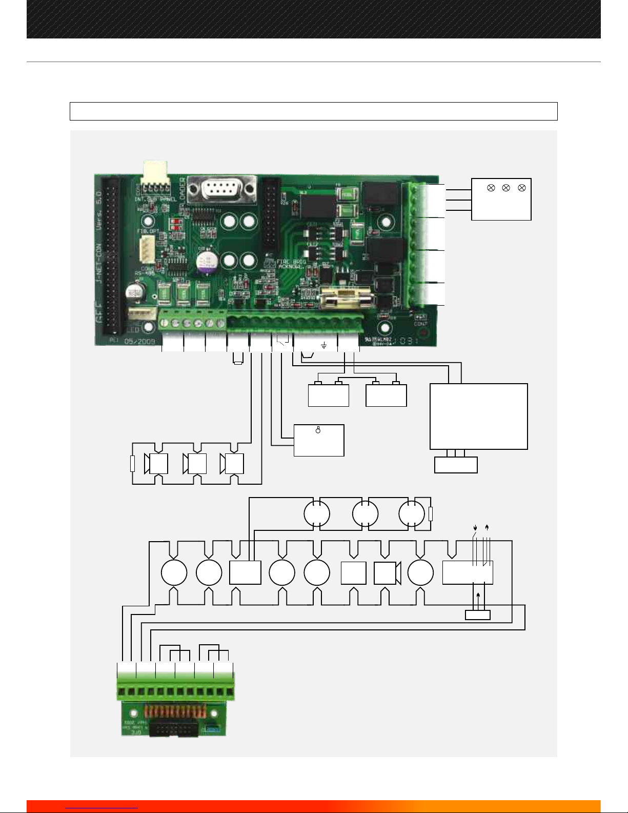
TYPICAL SYSTEM SCHEMATIC
ISOOPT ZMU TMP
BGU LSM
I/O
24 V
CON
DET
EOL
4K7
ION
EOL
10K
EOL
ALL AUX RELAYS RATED AT
50V AC/DC 1 AMP RESISTIVE
12V
POWER SUPPLY
L E N
110V/230V
A.C.
REPEATER
FIRE
FAULT
PRE
ALARM
CLASS CHANGE
OR
REMOTE EVAC.
MAX CURRENT
PER LAMP
=100mA
J-NET-LPCON
J-NET-CON
LOOP 1
OUT
LOOP 2
OUT
LOOP 3
OUT
LOOP 1
RETURN
LOOP 2
RETURN
LOOP 3
RETURN
+ -+ -+ -+ -+ -+ -
AUX 1
PSU
AUX 2
PSU
BELL 1 BELL 2
24v
BATT
EVAC
ZONE
MPX
OUT PF E SF24v0v 0v
0v
+ - + - + - + - + -
PAL
NO
NO
FIR
NC
NC
NC
REPEATSAUX 2FAULT AUX 1
FLT
C
C
C
+ -
12V
+ -
+
-
+
-
CON
DET
CON
DET
ISO
SNDSNDSND
9
Manufacturers of Fire Detection Equipment
INSTALLATION & COMMISSIONING MANUAL REVISION 4.0 05/2013
JUNO NET - NETWORKABLE ADRESSABLE PANEL
globalfire.pt
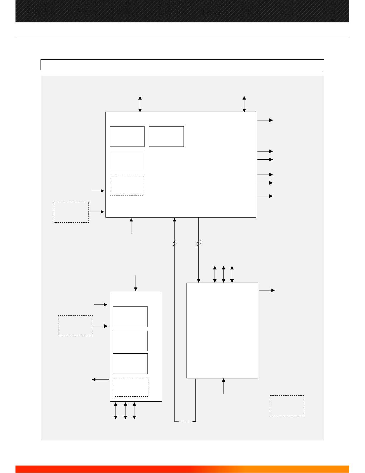
TYPICAL SYSTEM BLOCK DIAGRAM
GRAPHIC
SOFTWARE/MODEM
BMS
LCD
LCD
LEDs
LEDs
SWITCHES
SWITCHES
CONTROL PANEL
PRINTER
PSU
PSU
IN
IN
DATA
LOOP
DATA
LOOP
OUT
OUT
2 X RELAY (FIRE)
FIRE
FAULT
PRE-ALARM
3 X LOOPS
3 X LOOPS
IR KEYBOARD
IR KEYBOARD
PS/2
PC KEYBOARD
PS/2
PC KEYBOARD
REPEATER UNIT
2 X SOUNDER
OUTPUTS
2 X SOUNDER
OUTPUTS
2 X SOUNDER
OUTPUTS
SUB-PANEL
SUB-PANEL
4 4
MAX 32
SUB-PANELS
OPTIONS ARE
SHOWN THUS
1 X RELAY (FAULT)
10
Manufacturers of Fire Detection Equipment
INSTALLATION & COMMISSIONING MANUAL REVISION 4.0 05/2013
JUNO NET - NETWORKABLE ADRESSABLE PANEL
globalfire.pt
NEUTRO
FASE
1A
F
U
S
E
MEANWELL
MODEL: PS-65-27
INPUT: 100-240V AC 1.5A
OUTPUT: +27V 2.4A
50/60Hz
DANGER
220 VOLTS
NEUTRO
FASE
1A
F
U
S
E
2.4A POWER SUPPLY UNIT 5.6A POWER SUPPLY UNIT
Voltage
Current
Battery
EMC Standard EN55022 class B
EN61000-4-2,3,4,5,6,8,11
EN61000-3-2,3
2.4A PSU’s recommended for 1 or 3 loop stand-alone or networked panels.
5.6A PSU’s recommended for up to 9 loop self-contained or networked panels.
The maximum alarm sounder current is the power supply current (2.4A or 5.6A) less the panel's alarm current.
The maximum quiescent current per loop is 250mA. The loop short circuit (trip) current is 900mA.
Internal maximum 24V / 12AH
Primary supply voltage 230V AC +10%/-15%
MEANWELL
MODEL: LPP-150-27
INPUT: 85-264VAC ; 120-370VDC
OUTPUT: +27V 5.6A
47/63Hz
DANGER
220 VOLTS
POWER REQUIREMENTS
11
Manufacturers of Fire Detection Equipment
INSTALLATION & COMMISSIONING MANUAL REVISION 4.0 05/2013
JUNO NET - NETWORKABLE ADRESSABLE PANEL
globalfire.pt
BATTERY REQUIREMENTS
The battery AH required are calculated from the following formula
Round up to the next available battery size.
Quiescent currents for individual equipments are listed below:
X
X
(
(
)
)
+
+
20%
EQUIPMENT
QUIESCENT
CURRENT
(mA)
ALARM
CURRENT
(mA)
Main Panel
3 loop sub-panel
Device on loop
24V auxiliary outputs (2 off )
130
76
Refer to manufacturer's data
Refer to connected devices
150
105
Example
A given installation has a 6 loop panel with 58mA detector load, 1.4A sounder load (including loop sounders) and
a 24 hour standby requirement.
Quiescent current
in mA of the panel
with everything
connected.
Alarm current in Amps
(sounder load)
Standby time
required in hours
divided by 1000.
Alarm time
in hours.
X
X
X X
( () )
+
20%
130 (main panel)
+
2 x 76 (6 loops)
+
58 (detector load)
24 (standby in hrs)
divided by
1000
0.5
(alarm time in hrs)
150 (main panel)
+
2 x 10⁵ (6 loops)
+
58 (detector load)
=
340mA
=
8.16AH
= 9.069 AH +20% (1.81AH) = 10.88 AH
The next available battery size is 12AH
=
0.909AH
=
0.024H
=
0.5H
=
418mA +1.4A (sounder load)
=
1.818A
+
( () )
+
+
Quiescent current in mA
of the panel with
everything connected.
Standby time required
in hours divided by 1000.
Alarm current in Amps
(sounder load)
Alarm time in hours
12
Manufacturers of Fire Detection Equipment
INSTALLATION & COMMISSIONING MANUAL REVISION 4.0 05/2013
JUNO NET - NETWORKABLE ADRESSABLE PANEL
globalfire.pt
FIRE
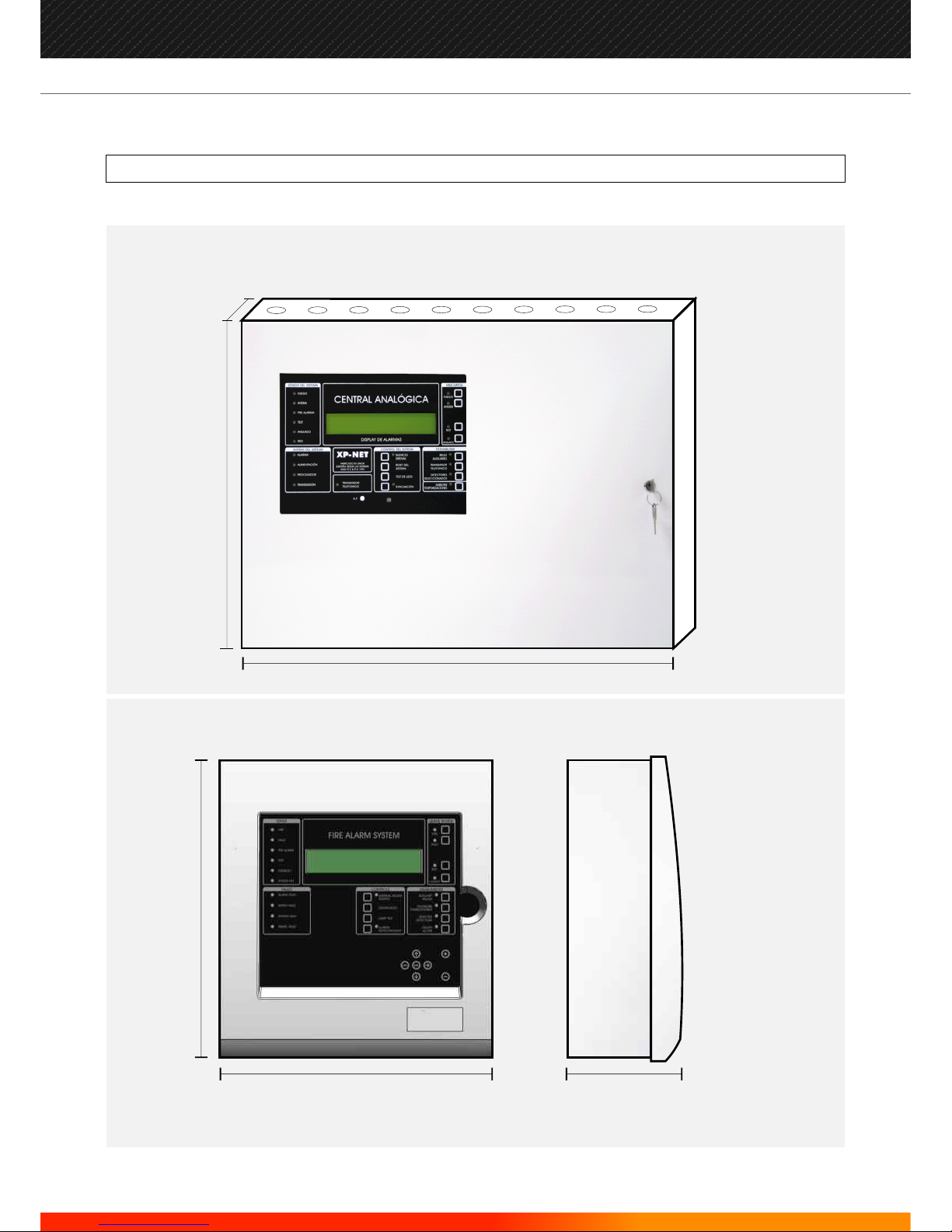
JUNO-NET Panel Box for 4 to 13 Loops
JUNO-NET Panel Box for 1 to 4 Loops
Panel boxes for Main Panels or Repeaters
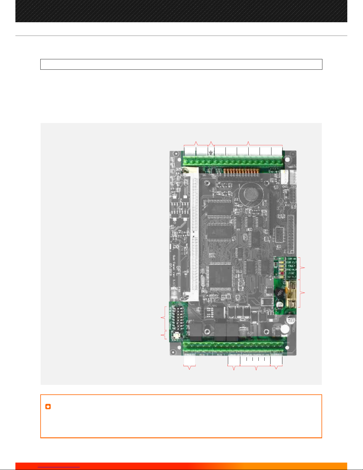
IDENTIFYING COMPONENTS
550 mm
420 mm
125 mm
Panel should be fixed to a flat surface using 4/5mm screws. Wall should be fitted with 4 plugs.
345 mm
375 mm
139 mm
13
Manufacturers of Fire Detection Equipment
INSTALLATION & COMMISSIONING MANUAL REVISION 4.0 05/2013
JUNO NET - NETWORKABLE ADRESSABLE PANEL
globalfire.pt
NEUTRO
FASE
1A
F
U
S
E
NEUTRO
FASE
1A
F
U
S
E
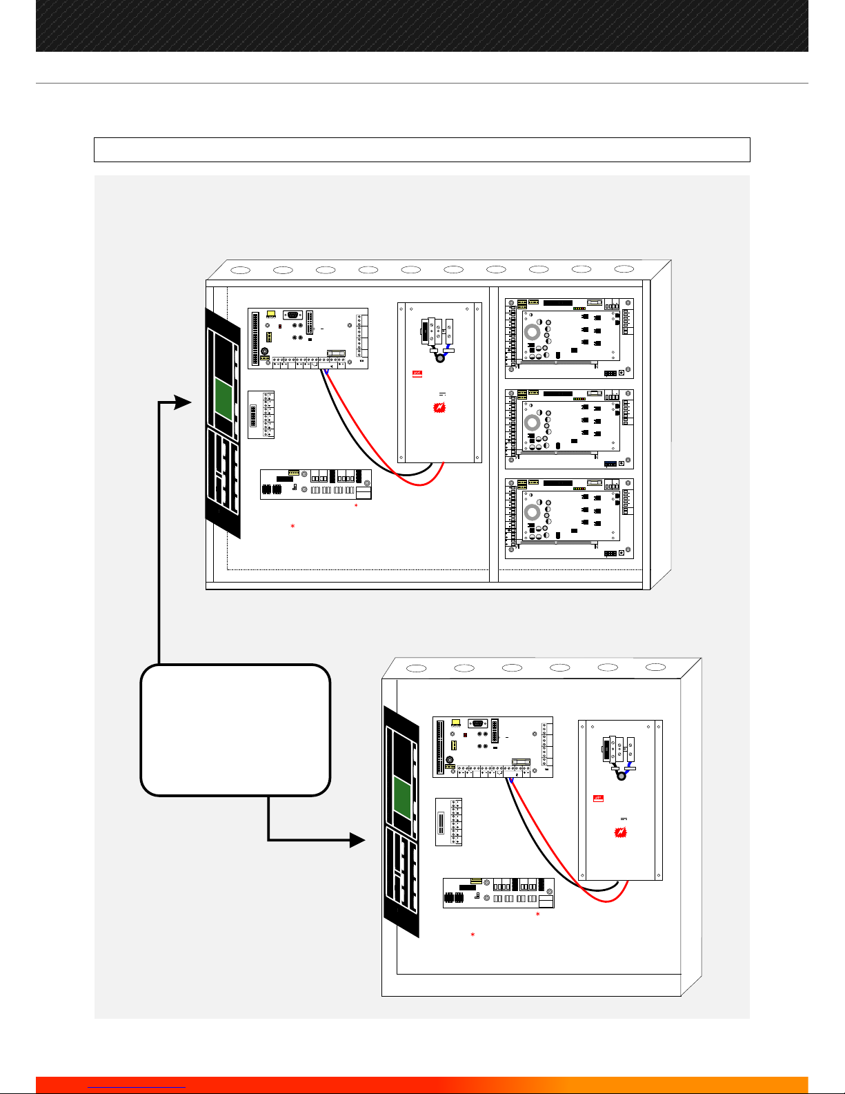
Inside a 1 to 12 Loop Self-Contained Panel Box
Inside a 1 to 3 Loop Panel Box
LOOP 1
OUT
LOOP 2
OUT
LOOP 3
OUT
LOOP 1
RETURN
LOOP 2
RETURN
LOOP 3
RETURN
LOOP 1
OUT
LOOP 2
OUT
LOOP 3
OUT
LOOP 1
RETURN
LOOP 2
RETURN
LOOP 3
RETURN
IDENTIFYING COMPONENTS (cont...)
FIRE
FAULT
PRE-ALARM
TEST
DISABLED
SYSTEM ON
ALARM FAULT
ALARM SILENCE
AUXILIARY
RELAYS
DISABLED
TEST
FAUL
T
FIRE
FIRE BRIGADE
TRANSMISSION
SELECTED
DETECTORS
ACTIVE
DELAYS
SYSTEM RESET
SOUND ALARMS
LAMP TEST
JUNONET
SUPPLY FAULT
PROC. FAUL
T
TRANS. FAUL
T
FIRE BRIGADE
ACKNOWLEDGED
PAPER FEED
MANUF
ACTURED TO THE
REQUIREMENTS OF
EN54 PT 2 1999
QUEUE
REVIEW
F
IRE
A
LARM S
YST
EM
ALARM DISPLAY
FIRE
FAUL
T
PRE
-ALARM
TEST
DISABLED
SYSTEM ON
ALARM FAULT
ALARM SILENCE
AUXILIARY
RELAYS
DISABLED
TEST
FAULT
FIRE
FIRE BRIGADE
TRANSMISSION
SELECTED
DETECTORS
ACTIVE
DELAYS
SYSTEM RESET
SOUND ALARMS
LAMP TEST
JUNONET
SUPPL
Y FAUL
T
PROC. FAUL
T
TRANS. FAUL
T
FIRE BRIGADE
ACKNOWLEDGED
PAPER FEED
MANUF
ACTURED T
O THE
REQUIREMENTS OF
EN54 PT 2 1999
QUEUE
REVIEW
FI
R
E ALA
R
M
S
YST
E
M
ALARM DISPLAY
On both of these panels,
the first 1 or 3 loops are
found on the mainboard
that is attached to the
metallic fascia of the panel.
RS485 INTERFACE
(OPTIONAL)
Only used, if there are externally
connected Sub-Panels
5A POWER SUPPLY UNIT
MEANWELL
MODEL: LPP-150-27
INPUT: 85-264VAC ; 120-370VDC
OUTPUT: +27V 5.6A
47/63Hz
DANGER
220 VOLTS
5A POWER SUPPLY UNIT
MEANWELL
MODEL: LPP-150-27
INPUT: 85-264VAC ; 120-370VDC
OUTPUT: +27V 5.6A
47/63Hz
DANGER
220 VOLTS
1 2 3 4 5 6
ON
SNDR 1 SNDR 2
LOOP 1
OUT
LOOP 2
OUT
LOOP 3
OUT
LOOP 1
RETURN
LOOP 2
RETURN
LOOP 3
RETURN
AUX PS
POWER SUPPLY IN
0V 0V 0V24V 28V28VMON
ETH
BATT
24V
EVAC
COMMS OK
COMMS FLT
PRE-ALARM
FAULT
5 VOLT FAULT
FIRE
PANEL NO
SILENCE
A
CN4
MPX
CN5
CN3
H8/3003
311
10050311
100
50
311
100
50
311
100
50
311
100
50
311
100
50
311
100
50
272
4R7
35
J-NET RS 485 INT.
RS 485 OUT RS 485 IN
A AA AB BB B
TX 1 RX 1RX 2 TX 2
MAIN PANEL
SUB PANEL or
REPEATERS
J1 & J2 OFF
J2
J1
J1 & J2 ON
RS485 INTERFACE
(OPTIONAL)
Only used, if there are externally
connected Sub-Panels or Repeaters
J-NET RS 485 INT.
RS 485 OUT RS 485 IN
A AA AB BB B
TX 1 RX 1RX 2 TX 2
MAIN PANEL
SUB PANEL or
REPEATERS
J1 & J2 OFF
J2
J1
J1 & J2 ON
MAX 3A FAST ACTING
MAX 3A FAST ACTING
MAX 3A FAST ACTING
J-NET-CON
J-NET-CON
J-NET-LPCON
J-NET-LPCON
J-NET-SP with LOOP-CARD
J-NET-SP with LOOP-CARD
J-NET-SP with LOOP-CARD
J-NET-RS485-INT-NEW
J-NET-RS485-INT-NEW
AUX 1
PSU
AUX 2
PSU
BELL 1 BELL 2
24v
BATT
EVAC
ZONE
MPX
OUT PF E SF24v0v 0v
0v
CON 2
ZONE LED
CON 5
FIRE BRIG.
ACKNOWL.
INT. SUB PANEL
FIB.OPT. / RS-485
CON 1
TX
RX
LOADER
CON 6
PAL
NO
NO
FIR
NC
NC
NC
REPEATSAUX 2FAULT AUX 1
FLT
C
C
C
MAX 3A FAST ACTING
CON 7
AUX 1
PSU
AUX 2
PSU
BELL 1 BELL 2
24v
BATT
EVAC
ZONE
MPX
OUT PF E SF24v0v 0v
0v
CON 2
ZONE LED
CON 5
FIRE BRIG.
ACKNOWL.
INT. SUB PANEL
FIB.OPT. / RS-485
CON 1
TX
RX
LOADER
CON 6
PAL
NO
NO
FIR
NC
NC
NC
REPEATSAUX 2FAULT AUX 1
FLT
C
C
C
MAX 3A FAST ACTING
CON 7
14
Manufacturers of Fire Detection Equipment
INSTALLATION & COMMISSIONING MANUAL REVISION 4.0 05/2013
JUNO NET - NETWORKABLE ADRESSABLE PANEL
globalfire.pt
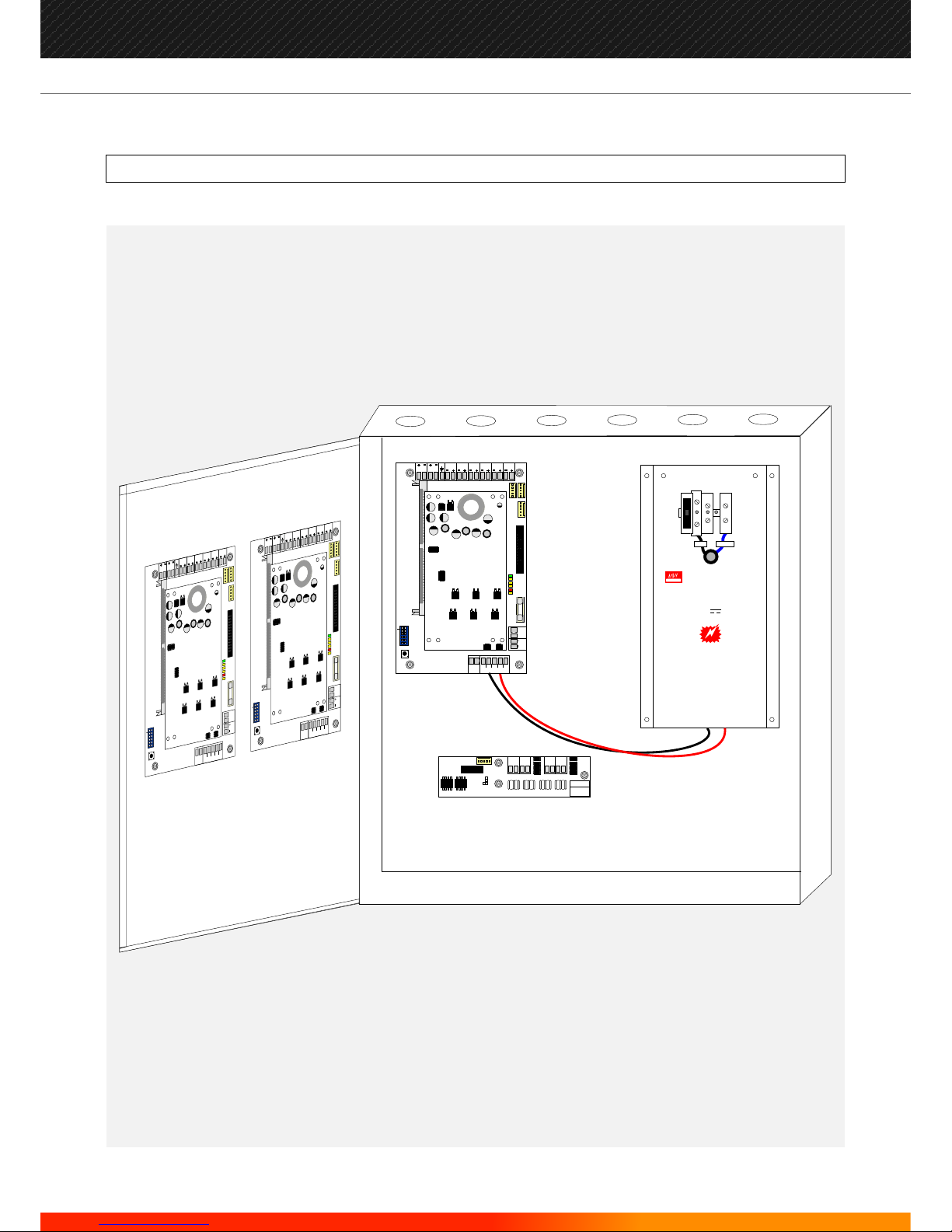
IDENTIFYING COMPONENTS (cont...)
Inside a Sub-Panel Box
Panel box for Sub-Panels
NEUTRO
FASE
1A
F
U
S
E
5A POWER SUPPLY UNIT
MEANWELL
MODEL: LPP-150-27
INPUT: 85-264VAC ; 120-370VDC
OUTPUT: +27V 5.6A
47/63Hz
DANGER
220 VOLTS
J-NET RS 485 INT.
RS 485 OUT RS 485 IN
A AA AB BB B
TX 1 RX 1RX 2 TX 2
MAIN PANEL
SUB PANEL or
REPEATERS
J1 & J2 OFF
J2
J1
J1 & J2 ON
1 2 3 4 5 6
ON
SNDR 1 SNDR 2
LOOP 1
OUT
LOOP 2
OUT
LOOP 3
OUT
LOOP 1
RETURN
LOOP 2
RETURN
LOOP 3
RETURN
AUX PS
POWER SUPPLY IN
0V 0V 0V24V 28V 28VMON
ETH
BATT
24V
EVAC
COMMS OK
COMMS FLT
PRE-ALARM
FAULT
5 VOLT FAULT
FIRE
PANE L NO
SILENCE
A
CN4
MPX
CN5
CN3
H8/3003
311
100
50
311
100
50
311
100
50
311
100
50
311
100
50
311
100
50
311
100
50
272
4R7
35
SUB-PANEL
1
1 2 3 4 5 6
ON
SNDR 1
SNDR 2
LOOP 1
OUT
LOOP 2
OUT
LOOP 3
OUT
LOOP 1
RETURN
LOOP 2
RETURN
L
OOP 3
RETURN
AUX PS
POWER SUPPL
Y IN
0V
0V
0V
24V
28V
28V
MON
ETH
BATT
24V
EVAC
COMMS OK
COMMS FL
T
PRE-ALARM
F
AUL
T
5 VOL
T FAUL
T
FIRE
PANEL NO
SILENCE
A
CN4
MPX
CN5
CN3
H8/3003
311
100
50
311
100
50
311
100
50
311
100
50
311
100
50
311
100
50
311
100
50
272
4R7
35
SUB
-P
ANEL
3
1 2 3 4 5 6
ON
SNDR 1
SNDR 2
L
OOP 1
OUT
LOOP 2
OUT
L
OOP 3
OUT
LOOP 1
RETURN
L
OOP 2
RETURN
LOOP 3
RETURN
AUX PS
POWER SUPPL
Y IN
0V
0V
0V
24V
28V
28V
MON
ETH
BATT
24V
EVAC
COMMS OK
COMMS FLT
PRE-ALARM
F
AUL
T
5 VOL
T F
AULT
FIRE
PANEL NO
SILENCE
A
CN4
MPX
CN5
CN3
H8/3003
311
100
50
311
100
50
311
100
50
311
100
50
311
100
50
311
100
50
311
100
50
272
4R7
35
SUB
-PANEL
2
J-NET-SP with LOOP
-
CARD
J-NET
-
SP with L
OOP-
CARD
J-NET-SP with LOOP-CARD
J-NET-RS485-INT-NEW
MAX 3A FAST ACTING
MAX 3A FAST ACTING
MAX 3A FAST ACTING
15
Manufacturers of Fire Detection Equipment
INSTALLATION & COMMISSIONING MANUAL REVISION 4.0 05/2013
JUNO NET - NETWORKABLE ADRESSABLE PANEL
globalfire.pt
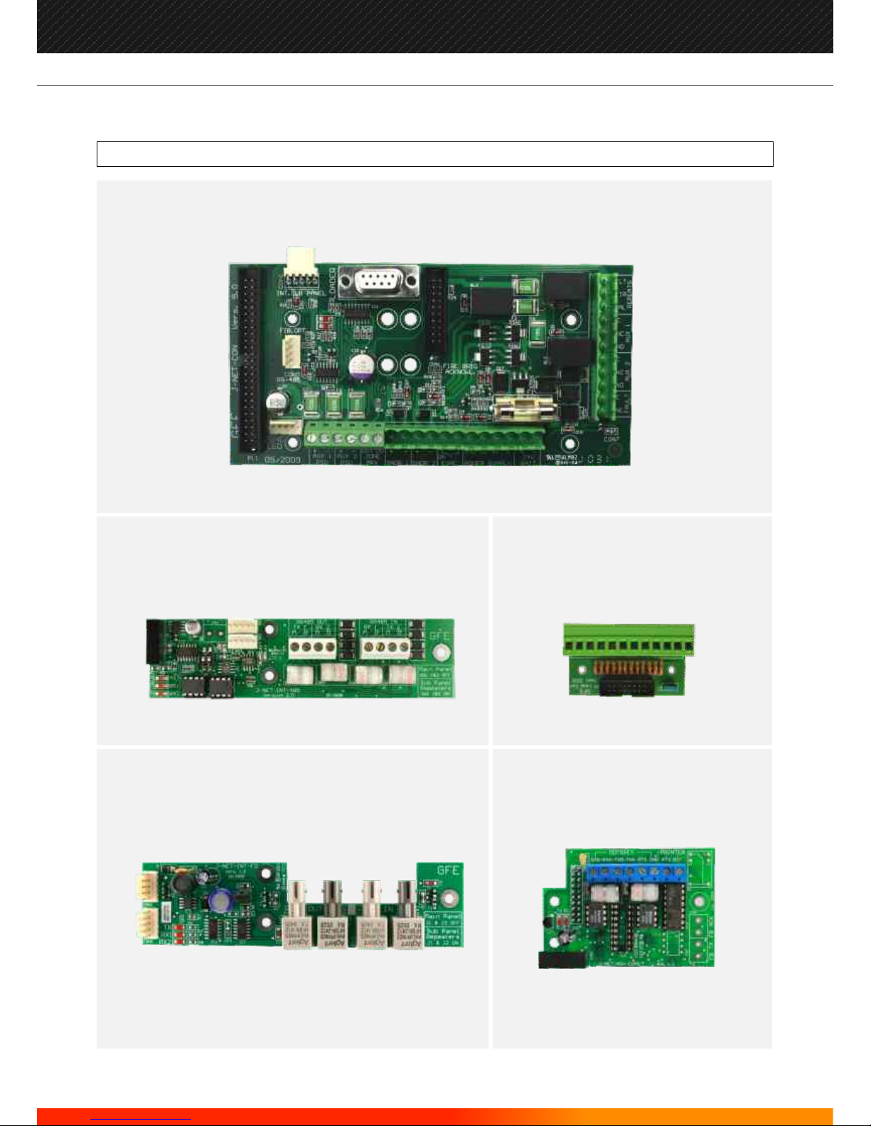
IDENTIFYING COMPONENTS (cont...)
J-NET-LPCON
JUNO-NET
ANALOGUE LOOP CONNECTOR
J-NET-INT-
JUNO NET INTERFACE FOR
RS485 COMMUNICATION
485
J-NET-INT-FO
JUNO-NET FIBRE OPTIC INTERFACE
J-NET-
INTERFACE
ADV-COMS
JUNO-NET COMMUNICATION
3 TYPES AVAILABLE:
RS232/485 - FIBRE OPTIC - TCP/IP
J-NET-CON
JUNO-NET-CONNECTOR BOARD
16
Manufacturers of Fire Detection Equipment
INSTALLATION & COMMISSIONING MANUAL REVISION 4.0 05/2013
JUNO NET - NETWORKABLE ADRESSABLE PANEL
globalfire.pt

IDENTIFYING COMPONENTS (cont...)
J-NET-SP
JUNO-NET-SUB-PANEL BOARD
1-LC or 3-LC
1 LOOP CARD or 3 LOOP CARD
17
Manufacturers of Fire Detection Equipment
INSTALLATION & COMMISSIONING MANUAL REVISION 4.0 05/2013
JUNO NET - NETWORKABLE ADRESSABLE PANEL
globalfire.pt
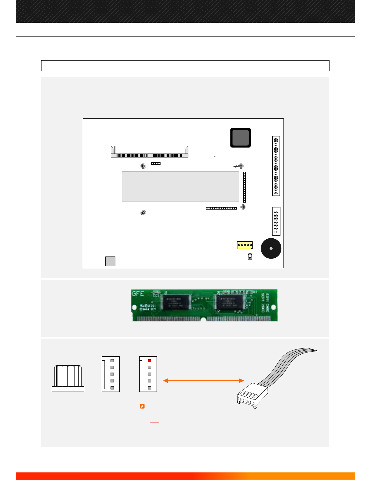
DISPLAY
1 A
LOOPCARD
HEADER
LOOPCARD HEADER
MASTER
RESET
PRINTER
CONNECTOR
PRINTER
FUSE
PS2 PC KEYBOARD
ADAPTOR
STANDOFFS (4) FOR LOOPCARD
SIM CARD CONNECTOR
QUAD UART
50 WAY BOX HEADER FOR
J-NET-CON
16 WAY BOX HEADER FOR
LOOP CONNECTOR
LOOPCARD HEADER
J-NET-QUART
QUAD UART
Juno Net - Motherboard (back view)
J-NET-SIM
JUNO-NET
SIM CARD
NOTE
THE PIN ON THE 5 WAY MOLEX
INDICATES WHICH PIN IS Nº1
THROUGHOUT THE MANUAL,
RED
Typical cable form
(one end)
VIEW FROM TOPVIEW FROM FRONT
MALE FEMALE
IDENTIFYING COMPONENTS (cont...)
18
Manufacturers of Fire Detection Equipment
INSTALLATION & COMMISSIONING MANUAL REVISION 4.0 05/2013
JUNO NET - NETWORKABLE ADRESSABLE PANEL
globalfire.pt

RECOMMENDED CABLES
Analogue Loops, Conventional Sounders and Data Loops
The JUNO-NET can be installed as either a self-contained or a distributed system. The self contained system does not require external
data loop connections. The distributed system requires a 4-core data loop cable for connection to remote sub-panels and Repeaters.
The data loop connects the Main Panel to the first Sub-panel and then to the second Sub-panel, etc., and eventually returns to the
Main Panel.
Fire rated Cables for Loops and Sounder Circuits
2 2
AEI type Firetec Multicore Ref. F1C1 (1 mm ) to F1C2.5 (2.5 mm ) in 2 core
2 2
AEI type Firetec Armoured Ref. F2C1 (1.5 mm ) to F2C2.5 (2.5 mm ) in 2 core
2
AEI type Mineral Insulated Cable (all types up to 2.5 mm
BICC types Mineral Insulated twin twisted conductor cables, Ref. CCM2T1RG and CCM2T1.5 RG
2
BICC types Mineral Insulated Pyrotenax (all types up to 2.5 mm )
2
CALFLEX type Calflam CWZ 2 core type up to 2.5 mm
2 2
PIRELLI type FP200 Gold 2 core type from 1 mm to 2.5 mm
2
FIRETUF (OHLS) FTZ up to 2.5 mm . Manufactured by Draka
All cables must be screened.
Minimum detection loop conductor section size is 0.5 sq.mm
Maximum detection loop conductor section size is 2.5 sq.mm
There should only be one analogue detector loop per shielded cable.
Analogue detector loops and conventional sounders should not run in the same shielded cable.
If the system requires one or more repeaters, it will be necessary to use a four core data cable to create a data loop between the panel
and the repeater. Alternatively, it is possible to use multi-mode dual-core fibre-optic cable or a TCP/IP connection for the same
purpose.
Data loop cable should be RS422/485 grade data cable, eg:
Signal cables for RS485 Communication Links (twisted pair) to Repeater panels
12 AWG Signal 88202 Belden 9583 WPW999
14 AWG Signal 88402 Belden 9581 WPW995
16 AWG Signal 88602 Belden 9575 WPW991
18 AWG Signal 88802 Belden 9574 WPW975
FIRETUF FDZ1000 by Draka 2 core
PIRELLI type FP200 Gold 2 core
PIRELLI type FP-PLUS
Fibre Optic: Multi.mode Dual Core sheathed fire proff with 62,5µ/125µ fibre terminated in ST connectors
LIMITATIONS
A fire alarm system can provide early warning of a developing fire but it does not assure protection against damage or loss
resulting from a fire.
The fire alarm system should be designed and installed in accordance with all relevant regulations and codes of practice.
To ensure maximum protection the system should be regularly tested and inspected by qualified fire alarm installation personnel.
Inspection and testing should be carried out in accordance with the appropriate local standards.
19
Manufacturers of Fire Detection Equipment
INSTALLATION & COMMISSIONING MANUAL REVISION 4.0 05/2013
JUNO NET - NETWORKABLE ADRESSABLE PANEL
globalfire.pt

DEFINITIONS
The physical link, usually fireproof 2 conductor shielded wiring cable, forming a ring of interconnection between
sensors and the detection panel.
A connecting lead. Typically a length of flat cable with connectors at both ends.
A Conventional Sounder is an audible output device that is connected to the Conventional Sounder outputs on a
Main Panel or Sub-panel. It is different electrically to a Loop powered Sounder.
This may take the form of RS485 or a fibre optic link. It provides communications between the Main Panel and
Repeaters or Sub-panels.
Any type of fire sensor (heat, smoke) that is connected to an Analogue Loop.
A detector, sounder, interface module or call-point connected to an Analogue Loop.
A system state where all sounders are activated simultaneously.
Pressing SOUND ALARMS will generate an evacuate condition.
A connection method for data that uses light instead of electrical signals. The connection is made using fibre optic
cables rather than copper electrical cables. Fibre optic signals can travel far greater distances than electrical signals
with less risk of electromagnetic interference.
Non-volatile memory inside the panel used to store the program and the customer site data. Flash data storage is
very robust and needs no power at all to retain the data.
A Main Panel or Repeater can have an Integrated Sub-panel. This is a single sub-panel that can support one or three
Analogue Loops.
A local conventional sounder is an audible output device (bell or sounder) that is connected to the local bell output
on a main or sub panel.
The term Loop Sounder is used to describe an audible output device that is connected to and controlled individually
by an Analogue Loop. Loop Sounders are different electrically from Conventional Sounders.
An installation only has one, and one only, Main Panel. This is the heart of the system, which monitors and controls all
the components in the system, although not always directly.
Analogue Loop
Cable form
Conventional Sounder
Data Loop
Detector
Device
Evacuate
Fibre Optic Link
Flash
Integrated Sub-panel (ISP)
Local Sounder
Loop Sounder
Main Panel
20
Manufacturers of Fire Detection Equipment
INSTALLATION & COMMISSIONING MANUAL REVISION 4.0 05/2013
JUNO NET - NETWORKABLE ADRESSABLE PANEL
globalfire.pt

NVRAM
PCB
Repeater
SIM CARD
Sub-panel
The System
Zone
Non-volatile Random Access Memory. Any information stored in this memory will not be cleared when power is
removed from the system. The system has an internal battery for the NVRAM.
Printed Circuit Board.
A Repeater is a remote terminal to the Main Panel. Everything that is displayed on the Main Panel is also displayed on
the Repeater. Any LEDs illuminated on the Main Panel are illuminated on the Repeater. Key presses and programming
input at the Repeater are sent directly to the Main Panel, as if the input were actually occurring at the Main Panel.
Single In-line Memory Card. Fitted to the SIM CARD is the Flash memory that contains the Main Panel software and
the system settings (Customer Flash Memory ).
These provide the Analogue Loops. Each Sub-panel supports one or three Analogue Loops. There are two types of
Sub-panels: Integrated and Standard. An integrated sub-panel consists of a loop card installed onto either the Main
panel or Repeater Motherboard. A standard Sub-panel consists of a loop card installed on a Sub-panel board which
is a basic fire control panel with its own CPU, local memory and fire signaling outputs. The Sub-panel reports all
events to the main panel but can operate individually in the event of communication loss. Up to 3 standard Subpanels can be housed within a Main Panel box. Additional Standard Sub-panels can be housed externally , and
typically, will be distributed around the building.
Sub-panels are connected to the Main Panel via the Data Loop.
The Main Panel, Sub-panels, Repeaters, and all devices.
A situational group of devices. A Zone can consist of a collection of any of the devices connected to the system.
21
Manufacturers of Fire Detection Equipment
INSTALLATION & COMMISSIONING MANUAL REVISION 4.0 05/2013
JUNO NET - NETWORKABLE ADRESSABLE PANEL
globalfire.pt
INTRODUCTION
This section covers the physical installation of the system. It primarily focuses on the parts that are required and how
they should be connected together. Do not connect the mains power or the batteries at this stage; commissioning
the system is covered in the next section of this manual.
Installation should always be performed in accordance with a system plan.
MAIN PANEL
The control panel should be located where access to the internal components is not restricted and where the unit is
not exposed to high levels of moisture, vibration and shock.
Avoid placing the panel in direct sunlight as this may impair programming using the infra-red keypad.
Any metal swarf could damage the PCBs if it is still present when the panel is powered up so it is recommended that
all PCBs are removed from the main box whilst the box is being installed. Make a note of the positions of the PCBs
before removal.
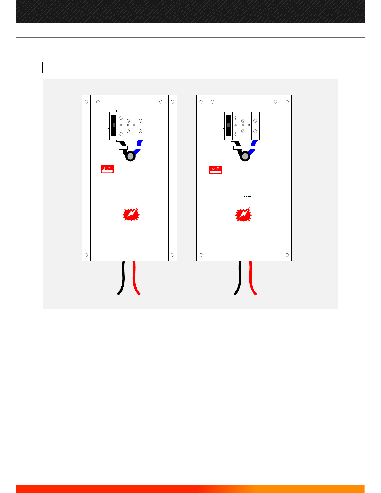
Mains Power Connection
The panel must be earthed.
The LIVE connection must be made to the fused input on the power supply module. This input will also have a BLACK
or BROWN wire leading into the power supply unit.
The connector with a BLUE wire leading into the power supply unit is the NEUTRAL.
These are detailed in the relevant following sections. Most connections are made from the J-NET-CON.
WARNING: observe ESD precautions when handling the PCBs.
Other Main Panel connections
INSTALLATION
ELECTRO-STATIC SENSITIVE DEVICES (ESD)
TAKE SUITABLE ESD PRECAUTIONS WHEN REMOVING OR
INSTALLING PRINTED CIRCUIT BOARDS.
22
Manufacturers of Fire Detection Equipment
INSTALLATION & COMMISSIONING MANUAL REVISION 4.0 05/2013
JUNO NET - NETWORKABLE ADRESSABLE PANEL
globalfire.pt

Integrated Sub-panels
A Main Panel may have an Integrated Sub-panel. To enable the Integrated Sub-panel a Loopcard must be fitted to the
Main Panel PCB. The Loopcard is secured on to 4 pillars behind the LCD module.
You may fit a 1 or 3 loop Loopcard.
If the Loopcard is fitted, an ANALOGUE LOOP CONNECTION BOARD is also required. This is mounted inside the Main
Panel box and requires a cable form between it and the Main Panel PCB.
Ensure all connectors are correctly aligned.
23
Manufacturers of Fire Detection Equipment
INSTALLATION & COMMISSIONING MANUAL REVISION 4.0 05/2013
JUNO NET - NETWORKABLE ADRESSABLE PANEL
globalfire.pt
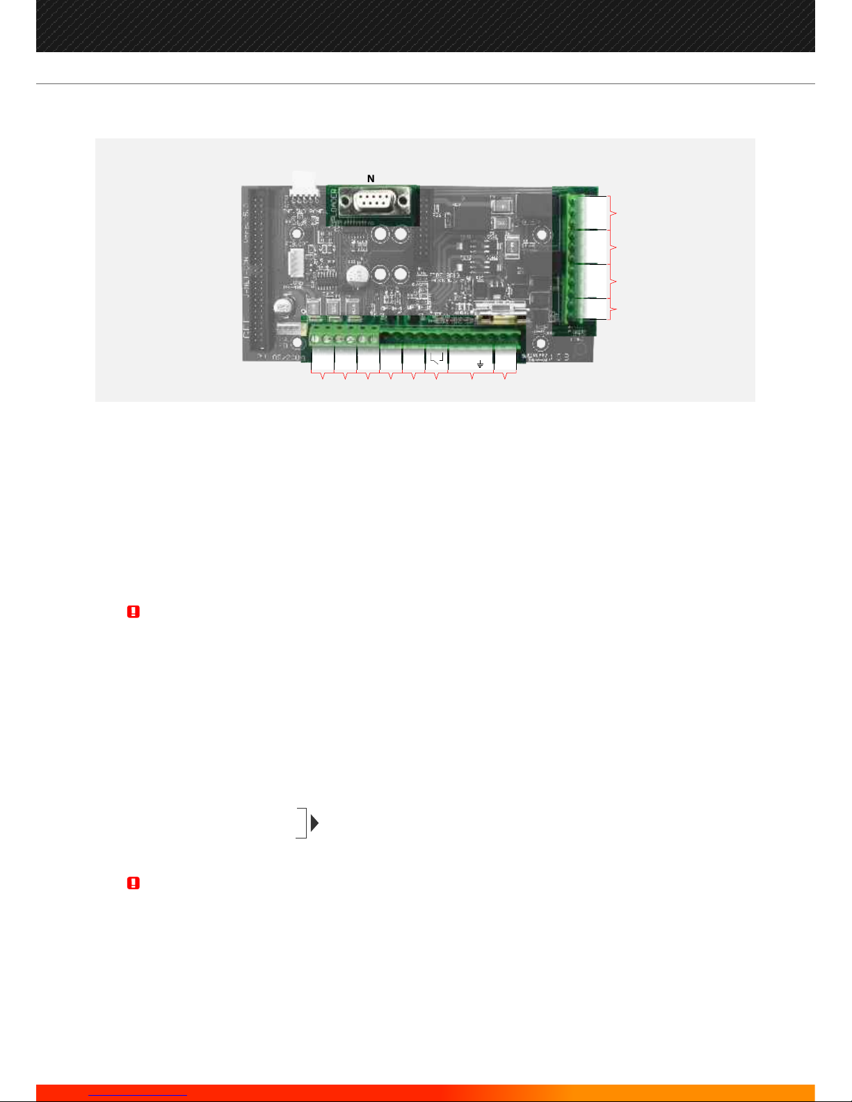
J-NET-CON
Auxiliary power supply output for powering external devices
Auxiliary power supply output for powering external devices
Both auxiliary power supply outputs are individually power limited and supervised
Max. Current Rating/ Output is 230 mA b@ 27.5 V DC nominal
Zone multiplex output for zone or mimic panel
Conventional Sounder Circuit 1
Conventional Sounder Circuit 2
Each Conventional Sounder Circuit is current limited and monitored for both open and short circuit fault conditions. The use in each circuit of
a 10 K ohms E.O.L. resistor is required.
Max. Current Rating/ Output is 400 mA @ 27.5 V DC nominal.
Remote Evacuation / Class Change Input. (Conventional sounder outputs only)
System Power Input (pre-wired and monitored)
Battery Connection
Earth Point
Auxiliary Fault Relay Output. (Activated by any fault present on the system)
This relay output will remain closed while there are no faults present in the system. Under any fault condition present, the relay will be deenergised and the relay contact will be open.
Auxiliary Fire Relay Output 2
Auxiliary Fire Relay Output 1
Under the presence of any Fire Alarm condition, these 2 relays will be energised. Both set of contacts are of the change-over type. Max.
Contact current rating for each set of relay contacts is 1 Amp @ 50 V AC/DC resistive.
Pre-alarm, Fault and Fire, Open Collector Outputs
Loader Interface: For Upload/Download Software
CON 1: Used to connect to other sub-panels within a self-contained panel
CON 5: Used for connecting RS485 , Fibre-Optic, and TCP/IP
CON 2: Used for MPX, Zone LEDs
The total current load of all detection loops, sounder circuits and auxiliary supply outputs should not exceed the maximum
power rating of the panel. Please refer to technical specification tables.
Relay outputs are not supervised. Please ensure that any wiring connected to these outputs is power limited.
WARNING:
WARNING:
A
B
C
D
E
F
G
H
I
J
K
L
M
N
O
P
Q
(Activated by any fire situation present
on the system, disabled by front button)
N
J
K
M
L
PAL
NO
NO
FIR
NC
NC
NC
REPEATSAUX 2FAULT AUX 1
FLT
C
C
C
A B
C D E F
HG
AUX 1
PSU
AUX 2
PSU
BELL 1 BELL 2
24v
BATT
EVAC
ZONE
MPX
OUT PF E SF24v0v 0v
0v
+ - + - + - + - + -
24
Manufacturers of Fire Detection Equipment
INSTALLATION & COMMISSIONING MANUAL REVISION 4.0 05/2013
JUNO NET - NETWORKABLE ADRESSABLE PANEL
globalfire.pt
REPEATERS
Repeaters are installed in a similar manner to the Main Panel.
Mini Rep repeaters are supplied by an external 24Vdc, normally from the control panel.
The Repeater should be located where access to the internal components is not restricted and where the unit is not
exposed to high levels of moisture, vibration and shock.
Avoid placing the Repeater in direct sunlight as this may impair programming using the infra-red keypad.
Any metal swarf could damage the PCBs if it is still present when the Repeater is powered up so it is recommended
that all PCBs are removed from the box whilst the box is being installed. Make a note of the positions of the PCBs
before removal.
WARNING: observe ESD precautions when handling the PCBs.
Mains Power Connection
The Repeater must be earthed.
The LIVE connection must be made to the fused input on the power supply module. This input will also have a BLACK
or BROWN wire leading into the power supply unit.
The connector with a BLUE wire leading into the power supply unit is the NEUTRAL.
Integrated Sub-panels
A Repeater may have an Integrated Sub-panel. To enable the Integrated Sub-panel a Loopcard must be fitted to the
Repeater PCB. The Loopcard is secured on to 4 pillars behind the LCD module.
You may fit a 1 or 3 loop Loopcard.
If the Loopcard is fitted an ANALOGUE LOOP CONNECTION BOARD is also required. This is mounted inside the
Repeater box and requires a cable form between it and the Repeater PCB.
Ensure all connectors are correctly aligned.
ELECTRO-STATIC SENSITIVE DEVICES (ESD)
TAKE SUITABLE ESD PRECAUTIONS WHEN REMOVING OR
INSTALLING PRINTED CIRCUIT BOARDS.
25
Manufacturers of Fire Detection Equipment
INSTALLATION & COMMISSIONING MANUAL REVISION 4.0 05/2013
JUNO NET - NETWORKABLE ADRESSABLE PANEL
globalfire.pt
J
K
D
E
AUX PS
POWER SUPPLY IN
0V 0V 0V24V 28V 28VMON
I
H
SNDR 1 SNDR 2
LOOP 1
OUT
LOOP 2
OUT
LOOP 3
OUT
LOOP 1
RETURN
LOOP 2
RETURN
LOOP 3
RETURN
ETH
CA B
+ - + -
+ -+ -+ -+ -+ -+ -
BATT
24V
FAULT
F
G
+ -
STANDARD SUB-PANELS
Standard Sub-panels need 28.5V DC to operate. This should be supplied from the Power Supply Unit found inside
the box.
Standard Sub-panels need a Loopcard fitted to operate. This fits on top of the sub-panel and almost completely
covers it. This is usually supplied fitted but if not ensure that all connectors are correctly aligned before fitting the 4
retaining screws.
NOTE:
and the 0V on the external power supply’s 0V connection. If the power supply is installed in the
same cabinet as the sub-panel, a link must be fitted between MON and 0V at the power supply IN
connection terminals.
To monitor an external power supply, a third wire should be connected between the MON
A - Conventional Sounder Outputs
B - Earth Connection
C - Analogue Loop Connections
D - Local status LEDs
E - 3 amp fuse
F - Evacuation Input
(conventional sounder circuits only)
G - Battery Connection (24V DC nominal)
H - Power Supply In (28.5V DC max)
I - 24V Auxiliary Supply Output
J - Emergency Silence/RAM initialize
K - Address Switch (DIP)
J-NET-SP
26
Manufacturers of Fire Detection Equipment
INSTALLATION & COMMISSIONING MANUAL REVISION 4.0 05/2013
JUNO NET - NETWORKABLE ADRESSABLE PANEL
globalfire.pt
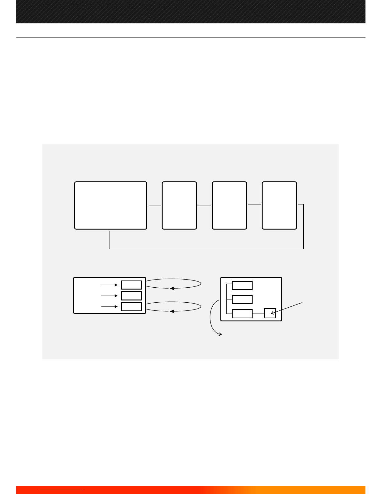
RS485, FIBRE OPTIC or TCP/IP
JUNO-NET TOPOLOGIES
RS485
SIMULTANEOUS
FIBRE OPTIC
RS485,
FIBRE OPTIC
or
TCP/IP
INTERFACE
If the system is distributed, the communication between the main panel and the external sub-panels or repeaters is
supported by either an RS422/485 fully redundant loop, fibre-optic cable or alternatively by TCP/IP.
For redundancy in the case of RS422/485 and Fibre Optic this can be wired in the form of a Loop, thus protecting the
Data Loop from interruptions or short circuits by creating a bi-directional communications flow. If the panel loses
communications with the repeater it will try via the opposite path.
RS422/485 may be used for distances of up to 1200m. For longer distances (up to 4,5km) Fibre Optic Data connections
should be used.
SUB
SUB
SUB
DIRECT TTL CONNECTION
BETWEEN UP TO THREE SUB-PANELS
MAIN
SUB
SUB
SUB
DIRECT TTL BUS
12 LOOPS
IN ONE BOX
MAIN
JUNO-NET
PANEL
SUB
PANEL
REPEATER
REPEATER
&
SUB
PANEL
27
Manufacturers of Fire Detection Equipment
INSTALLATION & COMMISSIONING MANUAL REVISION 4.0 05/2013
JUNO NET - NETWORKABLE ADRESSABLE PANEL
globalfire.pt
J-NET-RS485-INT-NEW
J-NET-CON
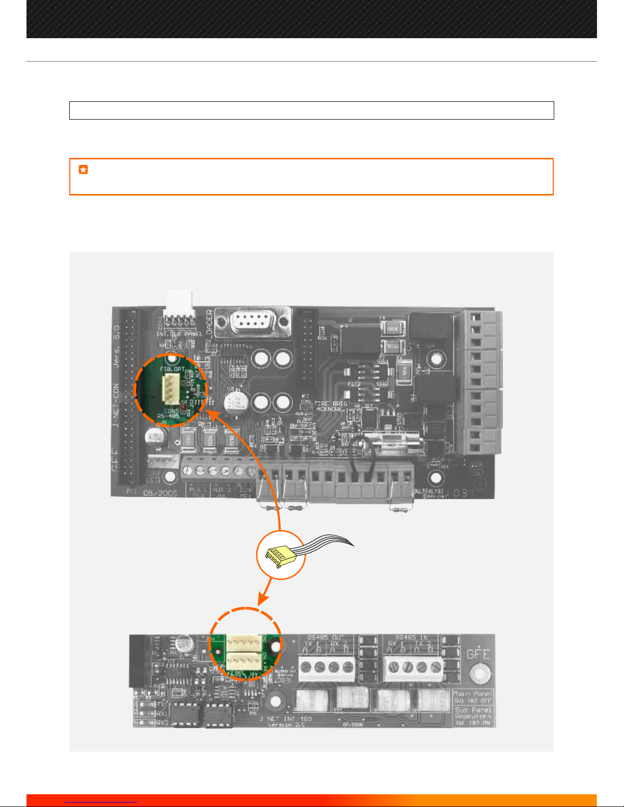
DATA LOOPS
Main Panel RS485
NOTE:
If an external data loop is required, the main panel will need an RS485, a FIBRE OPTIC or a TCP/IP
INTERFACE BOARD fitted to the main panel Connector Board.
Make all connections with the power turned off to avoid risk of permanent damage to
the circuit boards.
28
Manufacturers of Fire Detection Equipment
INSTALLATION & COMMISSIONING MANUAL REVISION 4.0 05/2013
JUNO NET - NETWORKABLE ADRESSABLE PANEL
globalfire.pt
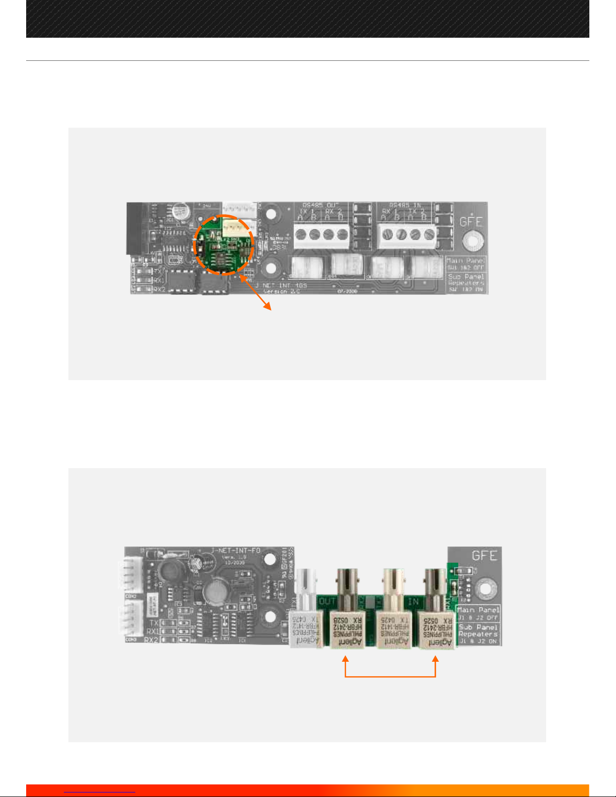
Data Loop Interface Configuration
If these interfaces are to be used at the Main Panel, all links on both the RS485 INTERFACE BOARD (J1 & J2) and FIBREOPTIC INTERFACE BOARD (LK1 & LK2) should be removed. When used on Repeaters or Sub-panels they should be
kept linked.
J-NET-INT-FO
J-NET-RS485-INT-NEW
LINKS -
MAIN PANEL = REPEATER / SUB-PANEL=
J1 & J2
OFF ON
LINKS
MAIN PANEL = REPEATER / SUB-PANEL= OFF ON
29
Manufacturers of Fire Detection Equipment
INSTALLATION & COMMISSIONING MANUAL REVISION 4.0 05/2013
JUNO NET - NETWORKABLE ADRESSABLE PANEL
globalfire.pt

Standard Sub-panel RS485
If more than one Sub-panel is mounted within a single enclosure, only one RS485 INTERFACE BOARD or FIBRE-OPTIC
INTERFACE BOARD needs to be used. The Standard Sub-panels will be interconnected via a TTL bus using a cable
form in a daisy-chain from CN4 in the first Sub-panel to CN3 in the next and on to CN3 on the RS485 INTERFACE
BOARD or CON1 on the FIBRE-OPTIC INTERFACE BOARD.
J-NET-RS485-INT-NEW
J-NET-SP
30
Manufacturers of Fire Detection Equipment
INSTALLATION & COMMISSIONING MANUAL REVISION 4.0 05/2013
JUNO NET - NETWORKABLE ADRESSABLE PANEL
globalfire.pt
 Loading...