

GLOBAL Export Import H.264 series User's Installation And Operation Manual
Page 1
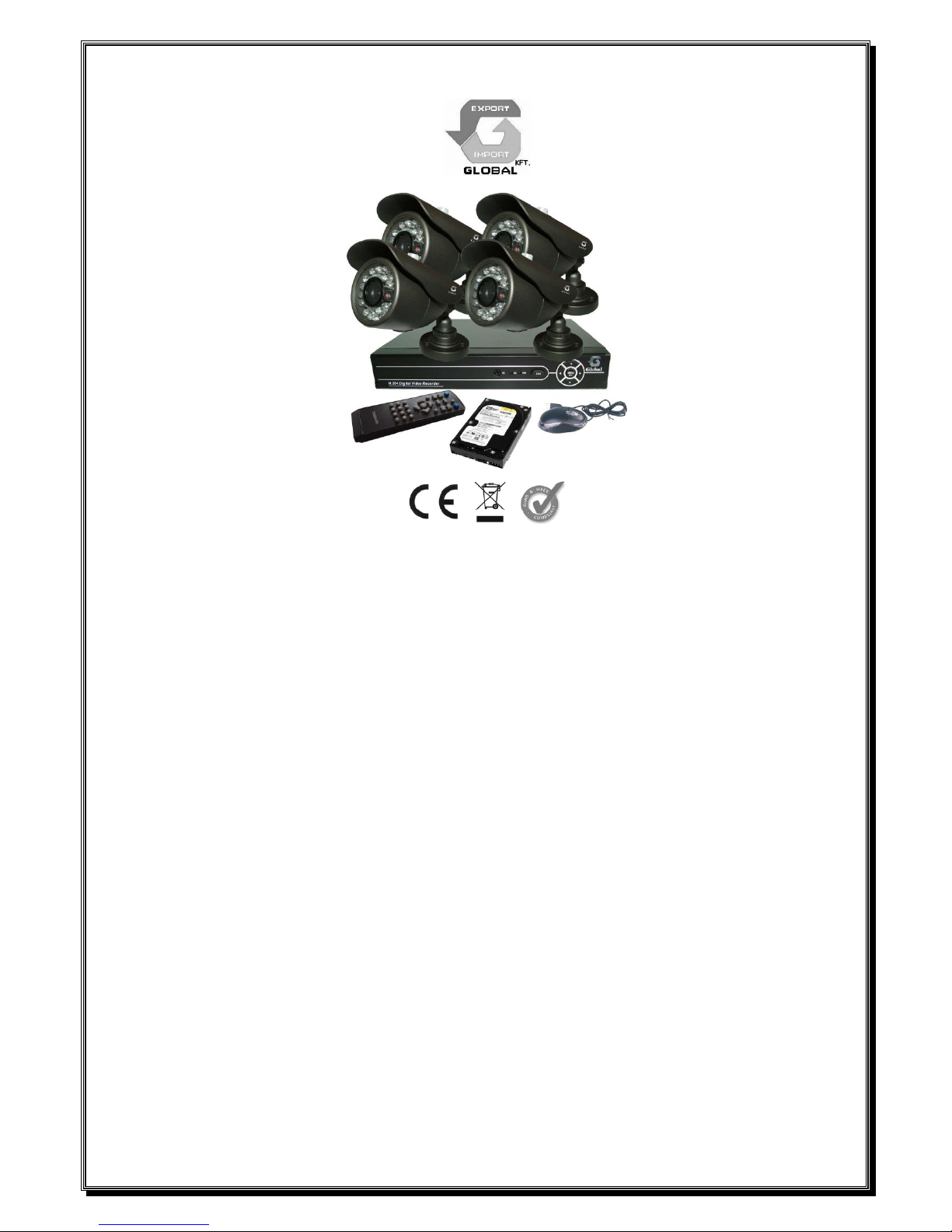
ART. NO. D1004+4XCC3084
H.264 series DVR User’s installation and operation
Manual
Edition R1.0
Welcome
Thank you for purchasing our DVR!
This manual is designed to be a reference tool for the installation and operation of your system.
Here you can find information about this series DVR features and functions, as well as a detailed menu
tree.
Before installation and operation please read the following safeguards and warnings carefully!
Important Safeguards and Warnings
Do not place heavy objects on the DVR.
Do not let any solid or liquid fall into or infiltrate the DVR.
Please brush printed circuit boards, connectors, fans, machine box and so on regularly. Before
the dust cleaning please switch off the power supply and unplug it.
Do not disassemble or repair the DVR by yourself. Do not replace the components by yourself.

Page 2
System
Model
D1004
Main Processor
High performance embedded microprocessor HI3515
Operating System
Embedded LINUX
System Resources
Pentaplex function: live, recording,playback,backup & remote access
User Interface
GUI,on-screen menu tips
Display
1/4
Video
Video Standards
PAL 625 line,50 f/s;NTSC 525 line,60 f/s
Video Compression
H.264 main profile
Video Recording
D1:PAL 1f/s-25f/s NTSC 1f/s-30f/s
Encode capacity
100/120fps(D1)
Motion Detection
Zones:396(22*18)detection zones,Sensitivity:1-6(6 is highest)
Trigger recording,PTZ movement,tour,alarm,email,snapshot & FTP
Audio
Audio Compression
G711A
Bidrectional Talk
Support
Record &
Playback
Recording Mode
Manual>Alarm>Video Detection>Continuous
Playback
Multi channels playback simultaneously,pause,stop,rewind,fast play,
slow play,next file,previous file,repeat,shuffle,backup selection
Search Mode
Time/Date,Alarm,Motion Detection & exact search(accurate to second)
Storage &
Backup
Space Occupation
Audio 28.8MB/H ;Video 25~450 MB/H
Record Storage
Local Hard disk and Network
Backup Mode
Network download/Flash stick/movable HDD/SATA HDD/DVD-RW
Interface
Video Input
4channel
Video Output
2 channel TV output BNC,1.0Vp-p,75Ω,1 VGA output(optional)
Audio Input
1 channel
Audio Output
1 channel
Net Interface
RJ-45 (10M/100M)
USB Interface
2 x USB2.0
Hard Disk
1 SATA ports(Max 2048G)
Environmental
Power Supply
12V/2A
Power Consumption
<10W(not include Hard disk)
Working Temperature
0°C-+55°C
Working Humidity
10%-90%
Atmosphere Pressure
86kpa-106kpa
Dimension
208MM*256MM*41MM
Weight
1KG

Page 3
Environment
Please place and use the DVR between 0℃ and 40℃.Avoid direct sunlight. Stay away from heat source.
Do not install the DVR in damp environment.
Do not use the DVR in smoky or dusty environment.
Avoid collision or strong fall.
Please insure the DVR level installation in a stable workplace.
Please install in ventilated place. Keep the vent clean.
Use within the rating input and output scope.
Directory
1 Production Introduction ............................................................................................................................ 5
1.1 Product overview ........................................................................................................................... 5
1.2 Main functions ............................................................................................................................... 5
2 Open-package check and cable connections .......................................................................................... 7
2.1 Open-package check ..................................................................................................................... 7
2.2 Hard disk installation ..................................................................................................................... 7
2.3 Front panel ..................................................................................................................................... 8
2.4 Rear panel ..................................................................................................................................... 8
2.5 Audio and video input and output connections ............................................................................. 9
2.5.1 Video input connections ...................................................................................................... 9
2.5.2 Video output connections and options ................................................................................ 9
2.5.3 Audio signal input .............................................................................................................. 10
2.5.4 Audio signal output ............................................................................................................ 10
2.6 Alarm input and output connections ............................................................................................ 10
2.6.1 Alarm input port specification ............................................................................................ 10
2.6.2 Alarm output port specification .......................................................................................... 10
2.6.3 Alarm output port relay parameters ................................................................................... 10
2.7 Speed dome connections ............................................................................................................. 11
3 Basic operation ...................................................................................................................................... 12
3.1 Turn on ......................................................................................................................................... 12
3.2 Turn off ......................................................................................................................................... 12
3.3 System Login ............................................................................................................................... 13
3.4 Preview ........................................................................................................................................ 13
3.5 Desktop shortcut menu ............................................................................................................... 14
3.5.1 Main menu ......................................................................................................................... 14
3.5.2 Playback ............................................................................................................................ 15
3.5.3 Record Mode ..................................................................................................................... 20
3.5.4 Alarm output ...................................................................................................................... 21
3.5.5 PTZ control ........................................................................................................................ 21
3.5.6 Color setting ...................................................................................................................... 24
3.5.7 Output adjust ..................................................................................................................... 25
3.5.8 Logout ............................................................................................................................... 25
3.5.9 Window switch................................................................................................................... 25
4 Main menu ............................................................................................................................................. 26
4.1 Main menu navigation ................................................................................................................. 26

Page 4
4.2 Record ......................................................................................................................................... 31
4.2.1 Record Config ................................................................................................................... 31
4.2.2 Snapshot Storage.............................................................................................................32
4.2.3 Playback ............................................................................................................................ 33
4.2.4 Backup .............................................................................................................................. 33
4.3 Alarm ............................................................................................................................................ 31
4.3.1 Motion Detect .................................................................................................................... 31
4.3.2 Video Blind ........................................................................................................................ 34
4.3.3 Video Loss ......................................................................................................................... 35
4.3.4 Alarm input ........................................................................................................................ 35
4.3.5 Alarm output ...................................................................................................................... 36
4.3.6 Abnormal ........................................................................................................................... 36
4.4 System ......................................................................................................................................... 40
4.4.1 General .............................................................................................................................. 40
4.4.2 Encode .............................................................................................................................. 41
4.4.3 Network ............................................................................................................................. 43
4.4.4 NetSevice .......................................................................................................................... 43
4.4.5 GUI Display ....................................................................................................................... 50
4.4.6 PTZ .................................................................................................................................... 51
4.4.7 RS232 ............................................................................................................................... 52
4.4.8 Tour .................................................................................................................................... 52
4.5 Advanced ..................................................................................................................................... 53
4.5.1 HDD Manage ..................................................................................................................... 53
4.5.2 Account .............................................................................................................................. 53
4.5.3 Online user ........................................................................................................................ 56
4.5.4 Output adjust ..................................................................................................................... 56
4.5.5 Auto maintain ..................................................................................................................... 56
4.5.6 Restore .............................................................................................................................. 55
4.5.7 Upgrade ............................................................................................................................. 57
4.5.8 Device Info........................................................................................................................58
4.6 Info ............................................................................................................................................... 56
4.6.1 HDD info ............................................................................................................................ 56
4.6.2 BPS ................................................................................................................................... 57
4.6.3 Log ..................................................................................................................................... 58
4.6.4 Version .............................................................................................................................. 59
4.7 Shut down system ....................................................................................................................... 59
5 FAQ and maintenance ........................................................................................................................... 60
5.1 FAQ .............................................................................................................................................. 60
5.2 Maintenance ................................................................................................................................ 65
Appendix 1.Remote controller operation .................................................................................................. 66
Appendix 2.Mouse operation .................................................................................................................... 67
Appendix 3.Hard disk capability calculation ............................................................................................. 68
Appendix 4.Technique parameters .......................................................... Hiba! A könyvjelző nem létezik.
Page 5
2 Open-package check and cable connections
2.1 Open-package check
When you receive the DVR, please check first .
First, please check whether there is any visible damage to the package appearance. The protective
materials used for the package of the DVR can protect most accidental clashes during transportation.
Then, please open the box and get rid off the plastic protective materials. Check whether there is
any visible damage to the DVR appearance.
At last, please open the machine crust and check the data wire in the front panel, power wire, the
connection between the fan power and the main board.
Front panel and rear panel
The key function specification in the front panel and the interface specification in the real panel
are in the specification.
Please check the product type in the front panel whether is accordant with the product type you
order.
The label in the real panel is very important for the after service. Please protect it carefully. When
you contact us for after service, please provide the product type and serial number in the label.
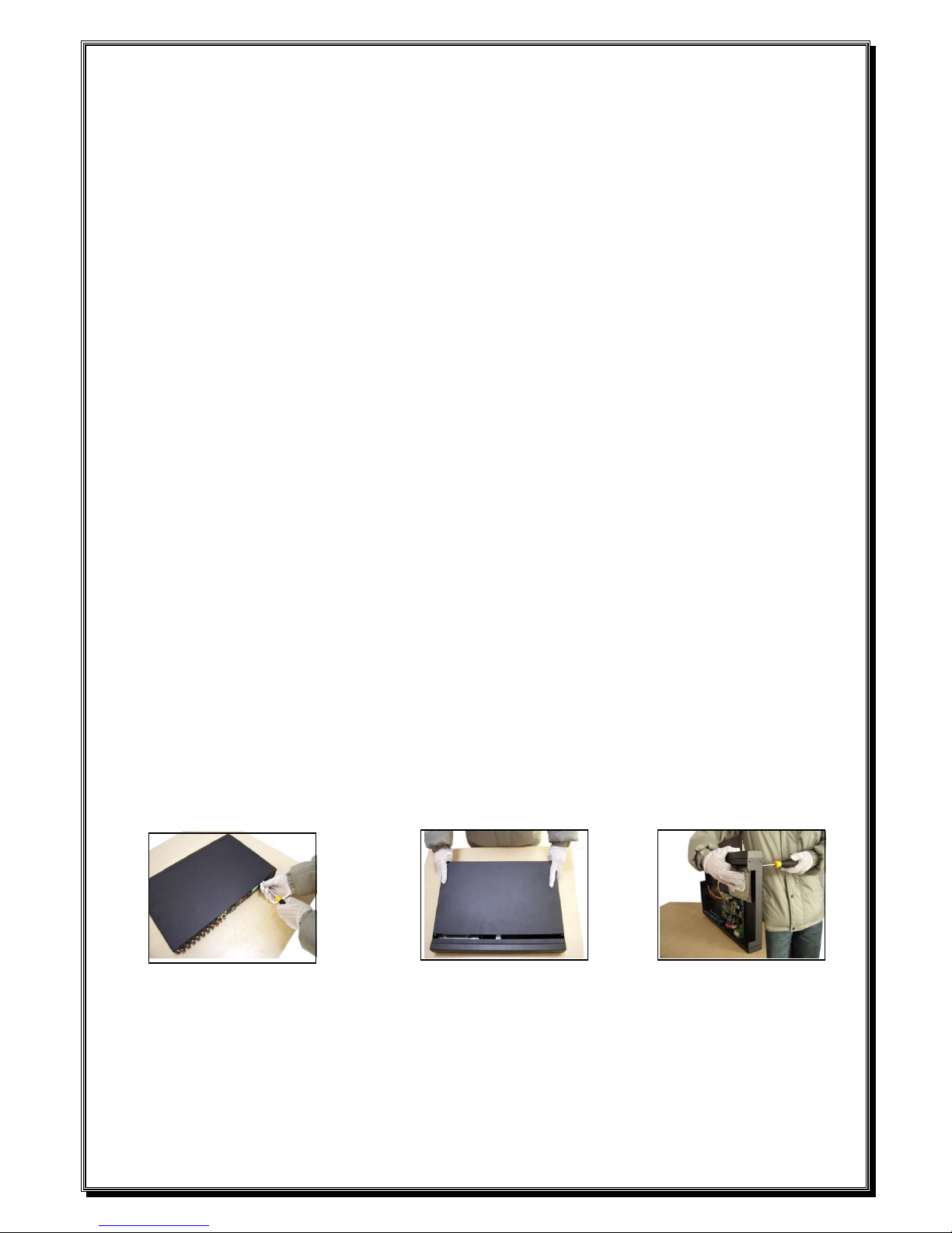
2.2 Hard disk installation
For the first use,please install the hard disk.
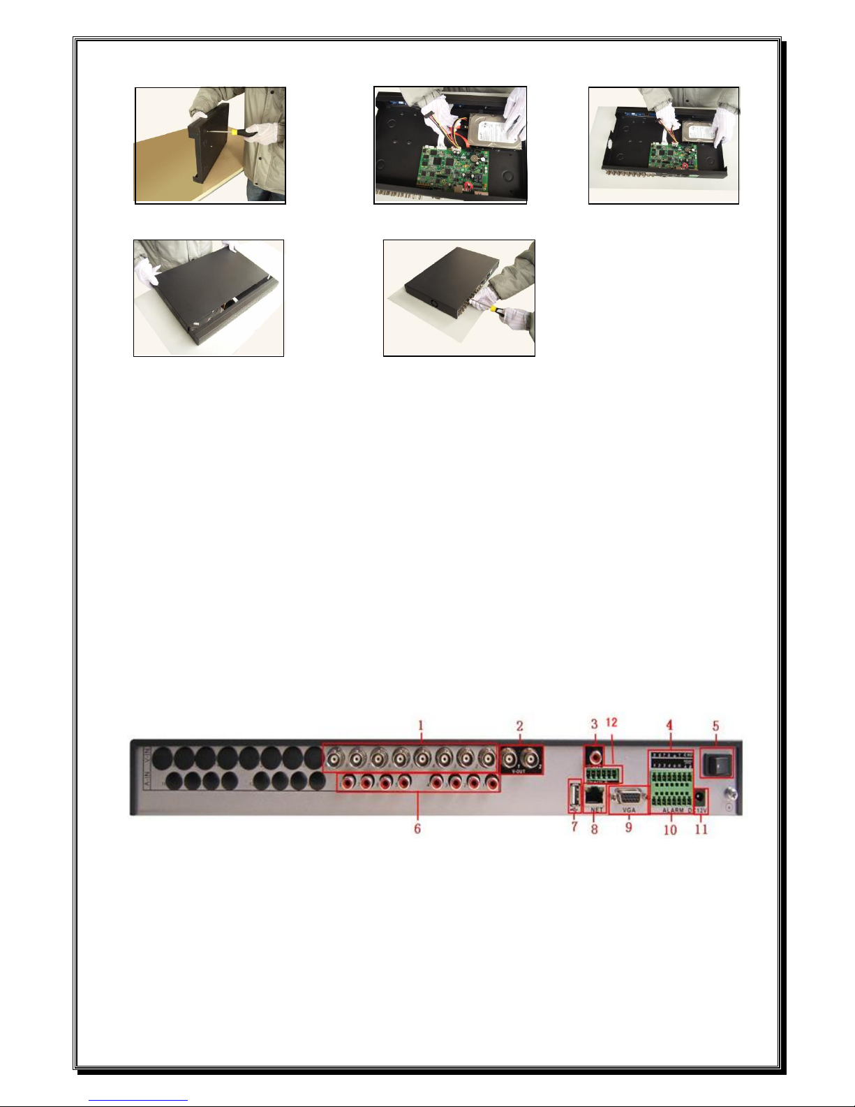
① disassemble the screw ②disassemble the cover ③fix the screw of hard disk
Page 6
④fix the screw of hard disk ⑤connect the data wire ⑥connect the power wire
⑦cover the machine ⑧fix the cover
2.3 Front panel
(1) Power indicator light (2) Shift indicator light (3) System status (4)Alarm indicator light
(5) Record indicator light (6) Outside operation indicator light (7) Network indicator light
(8) HDD indicator light (9) Function switch (10) Direction (11) ESC
(12) Power switch (13) Previous file (14) Next file (15) Slow play
(16) Fast play (17) Backward pause (18) Play Pause (19) 7
(20) 8 (21) 9 (22) Record (23) IR remote receiver
2.4 Rear panel
(1) video input (2) video output (3) audio output (4) Alarm & RS232 & RS485
(5) Switch (6) audio input (7) USB (8) network
(9) VGA (10) Alarm & RS232 & RS485 (11) Power supply
(12) 2 x 12V power output

Page 7
2.5 Audio and video input and output connections
2.5.1 Video input connections
The video input port is BNC connector plug. The demand of input signal is PAL/NTSC
BNC(1.0V
P-P
,75Ω).
The video signal must be accorded with the state standard which has the high signal to noise ratio,
low aberration and low interference. The image must be clear and has natural color in the appropriate
brightness.
Insure the vidicon signal stable and credible
The vidicon should be installed in the appropriate location where is away from backlighting and low
illumination or adopts the better backlighting and low illumination compensation.
The ground and power supply of the vidicon and the DVR should be shared and stable.
Insure the transmission line stable and credible
The video transmission line should adopt high quality coaxial pair which is chosen by the
transmission distance. If the transmission distance is too far, it should adopt shielded twisted pair, video
compensation equipment and transmit by fiber to insure the signal quality.
The video signal line should be away from the electro magnetic Interference and other equipments
signal lines. The high voltage current should be avoided especially.
Insure the connection stable and credible
The signal and shield lines should be firm and connected credible which avoid false and joint
welding and oxidation.
2.5.2 Video output connections and options
The video output is divided into PAL/NTSC BNC(1.0V
P-P
,75Ω) and VGA output(selective
configuration).
When replace the monitor by the computer display, there are some issues to notice.
1、Do not stay in the turn-on state for a long time.
2、Keep the computer display normal working by demagnetizing regularly.
3、Stay away from the electro magnetic Interference.
TV is not a credible replacement as a video output. It demands reducing the use time and control the

Page 8
power supply and the interference introduced by the nearby equipments strictly. The creepage of low
quality TV can lead to the damage of other equipments.
2.5.3 Audio signal input
Audio port is BNC connection.
The input impedance is high so the tone arm must be active.
The audio signal line should be firm and away from the electro magnetic Interference and connected
credible which avoid false and joint welding and oxidation. The high voltage current should be avoided
especially.
2.5.4 Audio signal output
Commonly the output parameter of DVR audio signal is greater than 200mv 1KΩ(BNC) which can
connect the low impedance earphone and active sound box or other audio output equipments through
power amplifier. If the sound box and the tone arm can not be isolated, howling phenomena is often
existed. There are some methods to deal with the above phenomena.
1、 Adopt better directional tone arm.
2、 Adjust the sound box volume to be under the threshold that produces the howling phenomena.
3、 Use fitment materials that absorb the sound to reduce reflection of the sound.
4、 Adjust the layout of the sound box and the tone arm.
2.6 Alarm input and output connections
1、Alarm input
A. Alarm input is grounding alarm input.
B. Alarm input demand is the grounding voltage signal.
C. When the alarm is connected with two DVRs or connected with DVR and other equipments, it
should be isolated by relay.
2、Alarm output
Alarm output can not be connected with high-power load(no more than 1A).When forming the output
loop it must prevent the big current from relay damage. Use the contact isolator when there is a
high-power load
Page 9
3、PTZ decoder connections
A. The grounding of the PTZ decoder and DVR must be shared otherwise the common-mode
voltage will lead to the PTZ control failure. The shielded twisted pair is recommended.
B. Avoid the entrance of high voltage. Make the layout reasonably. Take precaution from the
thunder.
C. In the outlying end connect 120Ω resistance paralleled to reduce the inflection and insure the
signal quality.
D. The 485 AB lines of DVR can not connected with other 485 output equipments paralleled.
E. The voltage between the AB lines of the decoder must be less than 5V.
4、Front equipment grounding note
Bad grounding can lead to the burnout of the chip.
5、Alarm input type unlimited
The DVR alarm output port is constant opening type.
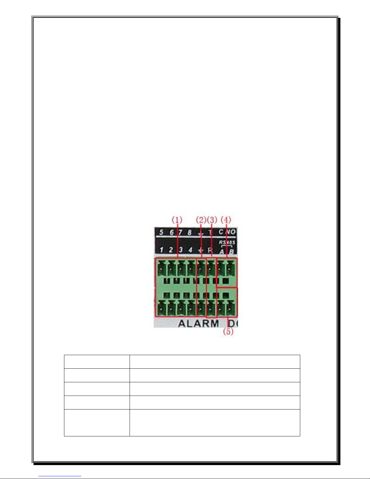
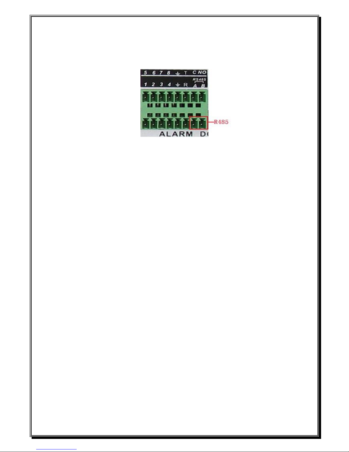
(1) alarm input (2) grounding (3) RS232 (4) alarm output (5) RS485
parameter
meaning
G
grounding
C1、NO1
Alarm output interface(constant open type)
T、R
RS232 port
A、B
485communication interface which is connected with the
recording control equipments such as the decoder

Page 10
2.6.1 Alarm input port specification
1 channels alarm input. Alarm input type unlimited.
The grounding and the com port of the alarm sensor are parallel (The alarm sensor is external power
supply) .
The grounding of the alarm and the DVR should be shared.
The NC port of the alarm sensor must be connected with the DVR alarm input port.
The grounding of the power supply and the alarm sensor must be shared when used in external power
supply.
2.6.2 Alarm output port specification
1 channels alarm output. There is external power supply when using the external alarm equipment.
Please refer to the relay relevant parameters to avoid the overload that damages main machine.
2.6.3 Alarm output port relay parameters
Type:JRC-27F
Interface material
silver
rating
(resistance load)
Rating switch capacity
30VDC 2A, 125VAC
maximal switch power
125VA 160W
maximal switch voltage
250VAC, 220VDC
maximal switch current
1A
isolation
Homo-polarity
1000VAC 1minute
Inhomo-polarity
1000VAC 1 minute
Interface and winding
1000VAC 1 minute
Surge voltage
Homo-polarity
1500VAC (10×160us)
Turn-on time
3ms max
Turn-off time
3ms max
longevity
mechanical
50×106 MIN(3Hz)
electric
200×103 MIN (0.5Hz)
Environment
-40~+70℃
Page 11
2.7 Speed dome connections
1、Connect the 485 lines of the speed dome with the DVR 485 interface.
2、Connect the video line with the DVR video input.
3、Electrify the speed dome.

Page 12
3 Basic operation
Note: The button in gray display indicates nonsupport.
3.1 Turn on
Plug the power supply and turn on the power supply switch. Power supply indicator light shining
indicates turning on the video recorder. After the startup you will hear a beep. The default setting of video
output is multiple-window output mode. If the startup time is within the video setting time, the timing video
recording function will start up automatically. Then the video indicator light of corresponding channel is
shining and the DVR is working normally.
Note:1. Make sure that the input voltage corresponds with the switch of the DVR power supply.
2. Power supply demands: 220V±10% /50Hz.
Suggest using the UPS to protect the power supply under allowable conditions.
3.2 Turn off
There are two methods to turn off the DVR. Entering [main menu] and choosing [turn off] in the [turn
off the system] option is called soft switch. Pressing the power supply switch is called hard switch.
Illumination:
1、Auto resume after power failure
If the DVR is shut down abnormally, it can automatically backup video and resume previous
working status after power failure.
2、Replace the hard disk
Before replacing the hard disk, the power supply switch in the real panel must be turned off.
3、Replace the battery
Before replacing the battery, the setting information must be saved and the power supply switch
in the real panel must be turned off. The DVR uses button battery. The system time must be checked
regularly. If the time is not correct you must replace the battery, we recommend replacing the battery
every year and using the same battery type.
Note: The setting information must be saved before replacing the battery otherwise information
will lose.
Page 13
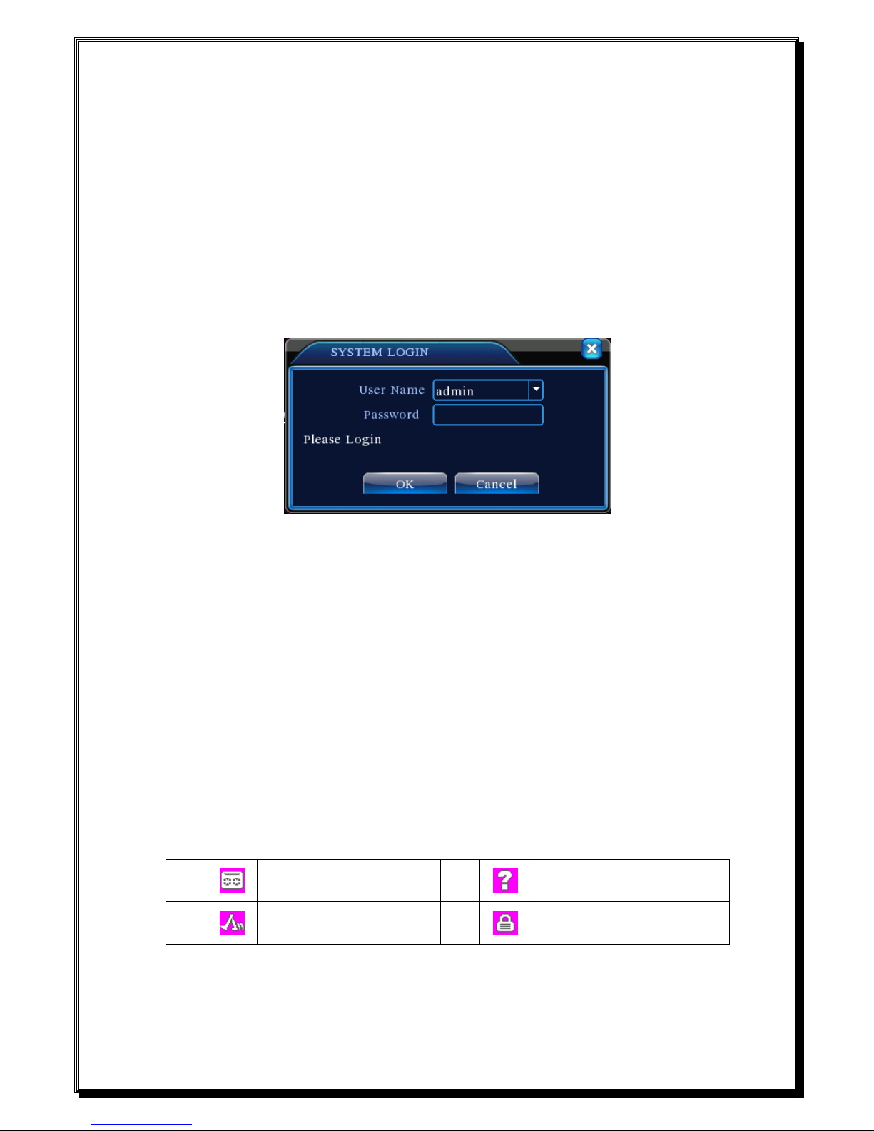
3.3 System Login
When the DVR boots up, the user must login and the system provides the corresponding functions
with the user purview. There are three user settings. The names are admin, guest and default and
these names have no password. Admin is the super user purview; guest and default’s permissions are
preview and video playback. User admin and guest’s password can be revised, while their permissions
can’t be revised; user default is the default login user whose permission can be revised but not its
password.
Picture 3.1 System Login
Password protection: If the password is continuous wrong three times, the alarm will start. If
the password is continuous wrong five times, the account will be locked. (Through reboot or after
half an hour, the account will be unlocked automatically).
For your system security, please modify your password after first login.
3.4 Preview
You can right click mouse to choose the switch between the windows.
The system date, time and channel name are shown in each viewing window. The surveillance video
and the alarm status are shown in each window.
1
Recording status
3
Video loss
2
Motion detect
4
Camera lock
Table 3.1 Preview icon
Page 14
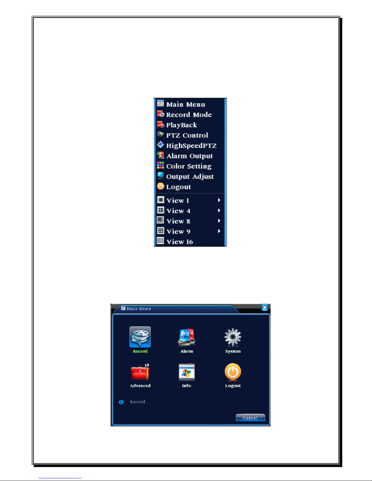
3.5 Desktop shortcut menu
In preview mode you can right click mouse to get a desktop shortcut menu. The menu includes:
main menu,record mode,playback,PTZ control,High Speed PTZ,Alarm Output,color
Setting,Output adjust,Logout,view1/4/8/9/16 screens.
Picture 3.2 Shortcut Menu
3.5.1 Main menu
When you login, the system main menu is shown as below.
Picture3.3 Main Menu
Page 15
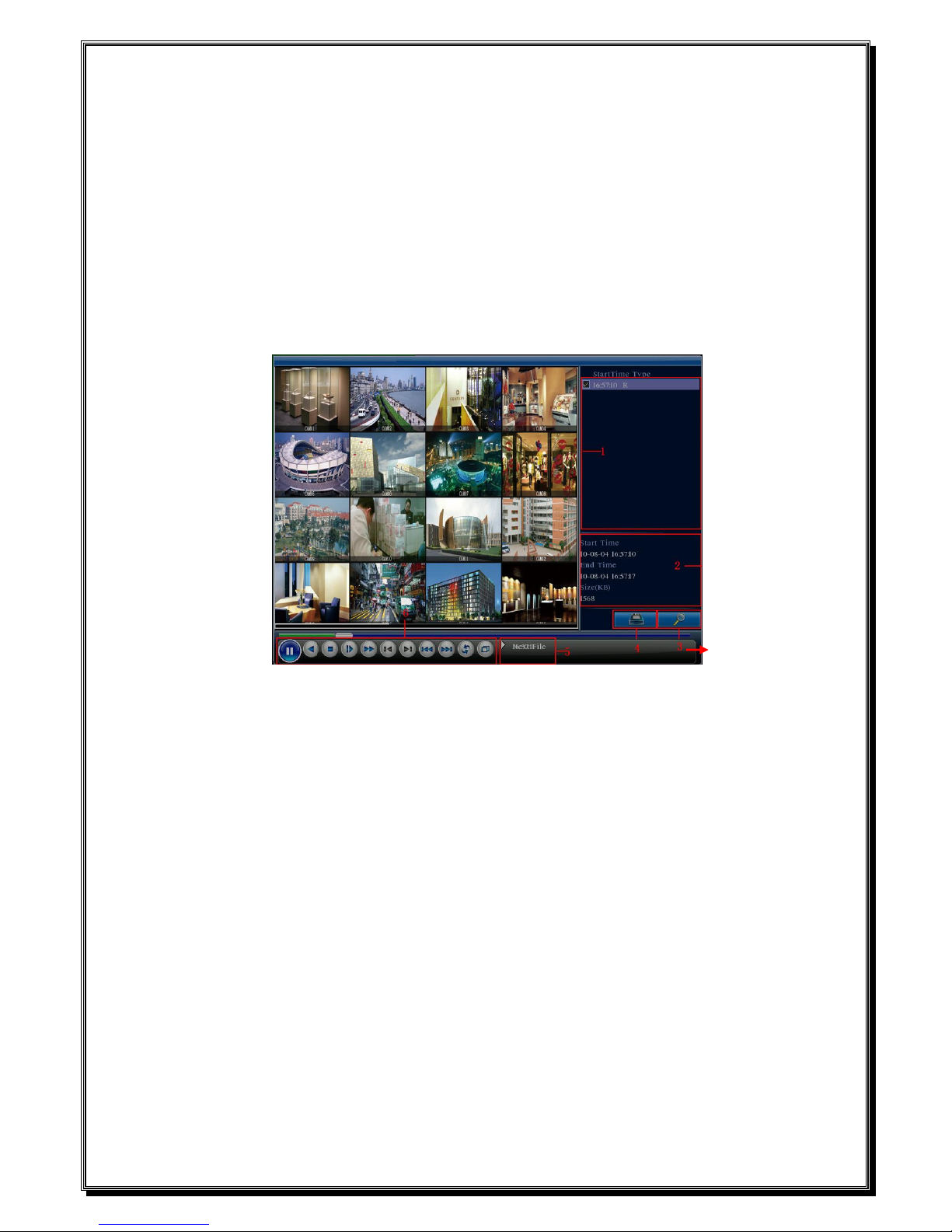
3.5.2 Playback
There are two methods for you to play the video files in the hard disk.
1、 In the desktop shortcut menu.
2、 Main menu>Record->Playback
Note: The hard disk that saves the video files must be set as read-write or read-only state.(4.5.1)
Picture 3.4 video playback
1. listed files 2. file information 3. file searching
4. file backup 5. Operation hint 6. Playback control
【Listed files】Look up the listed files that accord with the searching criteria.
【File information】Look up the found file information.
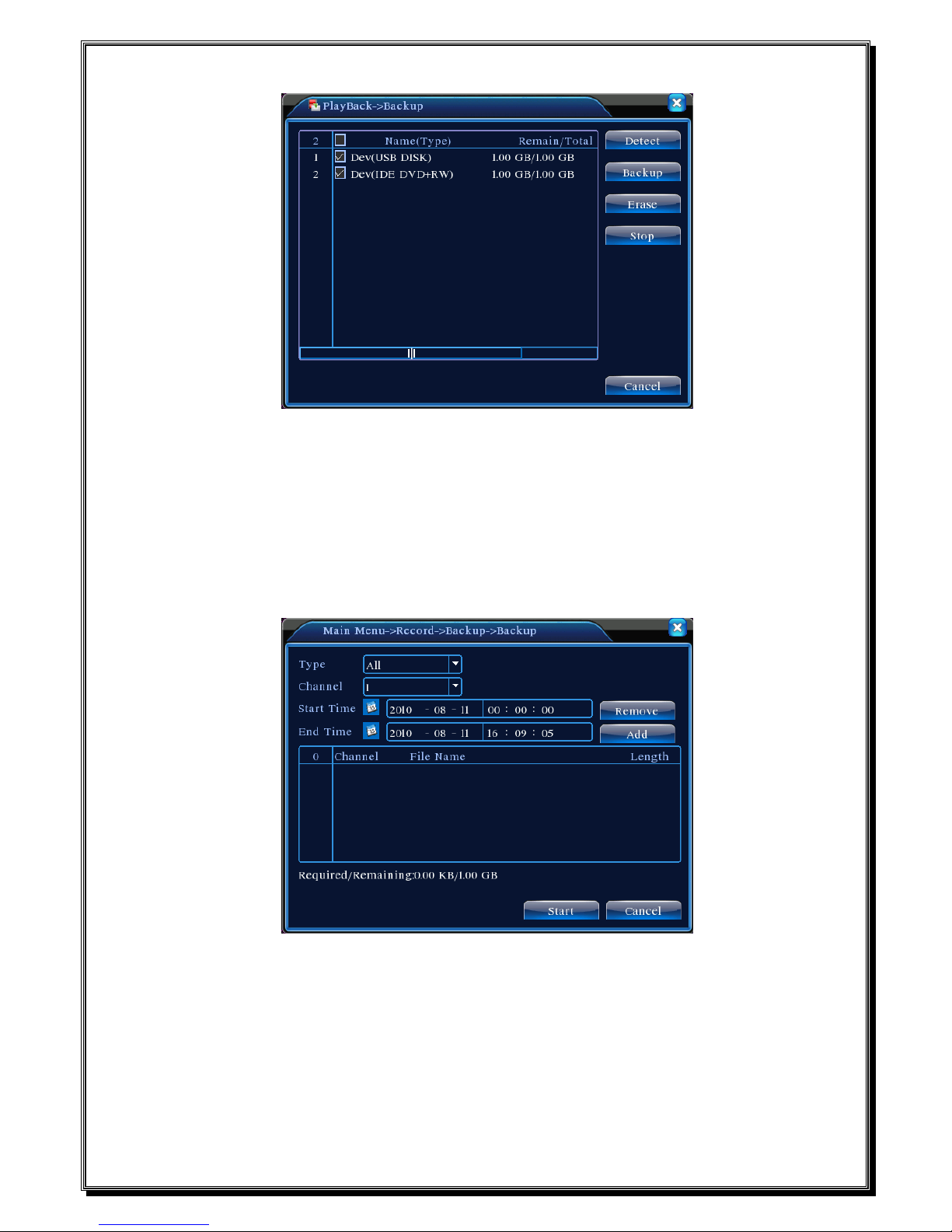
【File backup】Backup the chosen file. Click the button and operate as followed.
Note: The storage must be installed before the file backup. If the backup is terminated, the
already backup can playback individually.
Page 16
Picture 3.5 detect the storage
Detect: Detect the storage connected with the DVR such as hard disk or universal disk.
Erasure: Choose the file to delete and click erasure to delete the file.
Stop: Stop the backup.
Backup: Click backup button and the dialog box is popped up. You can choose the backup file
according to the type, channel and time.
Picture 3.6 recording backup
Remove:Clear the file information.
Add:Show the file information satisfying the set file attributes.
Start/Pause:Click the play button to start the backup and click the pause button to stop the
backup.
Cancel:During backup you can exit the page layout to carry out other functions.
Page 17
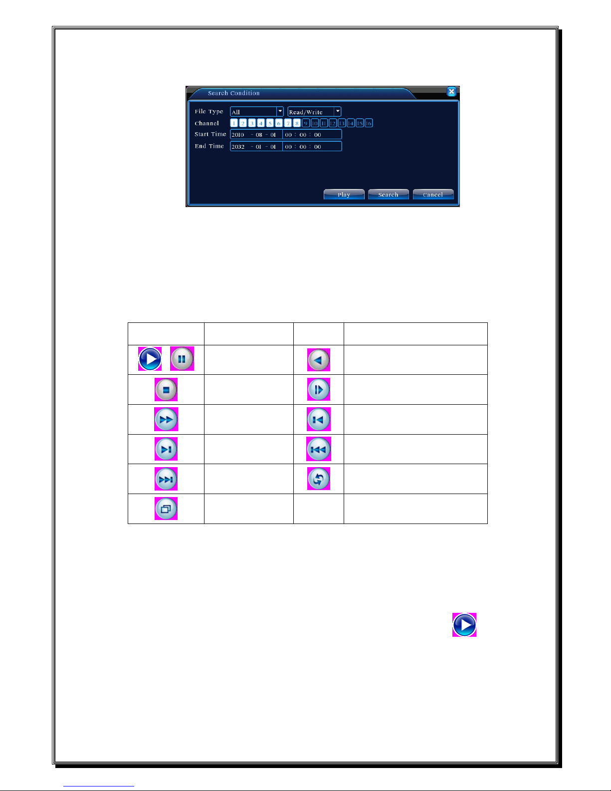
【File searching】Search the file according to the searching parameter.
Picture 3.7 file searching
File type: Set the searching file type.
Channel: Set the searching channel.
Start Time: Set the searching time scan.
【Playback control】Refer to the following sheet for more information.
Button
Function
Button
Function
/
Play/pause
Backward
Stop Slow play
Fast play
Previous frame
Next frame
Previous file
Next file Circulation
Full screen
Table 3.2 Playback control key
Note: Frame by frame playback is only performed in the pause playback state.
【Operation hint】Display the function of the cursor place.
Special functions:
Accurate playback:Input time (h/m/s) in the time column and then click play button. The
system can operate accurate playback according to the searching time.
Local zoom:When the system is in single-window full-screen playback mode, you can drag your
mouse in the screen to select a section and then left click mouse to realize local zoom. You can right click
mouse to exit.
Page 18
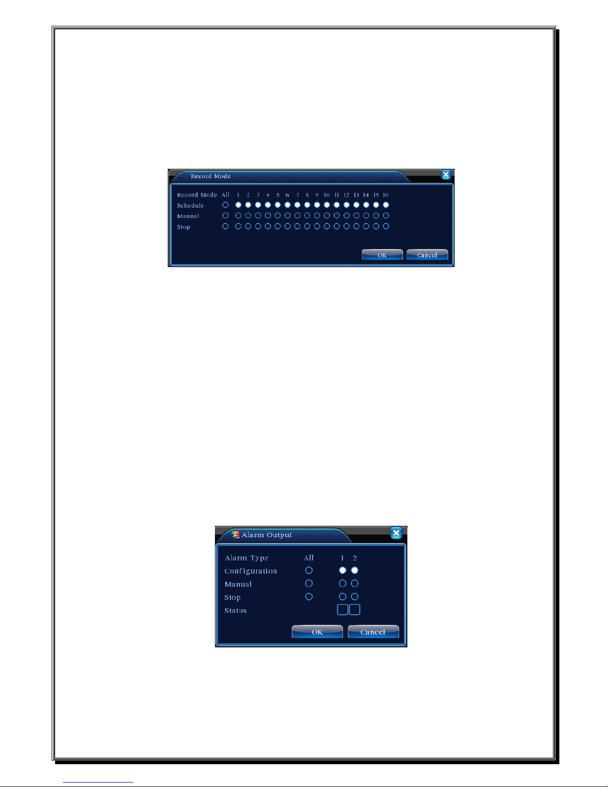
3.5.3 Record Mode
Please check current channel status: “○” means it is not in recording status, “●” means it is in
recording status.
You can use desktop shortcut menu or click [main menu]> [recording function]> [recording set]
to enter the recording control interface.
Picture 3.8 Record Mode
【Schedule】Record according to the configuration.
【Manual】Click the all button and the according channel is recording no matter the channel in any
state.
【Stop】Click the stop button and the according channel stops recording no matter the channel in
any state.
3.5.4 Alarm output
Please check current channel status: “○” means it is not in alarming status, “●” means it is in
alarming status.
You can use desktop shortcut menu or click [main menu]> [alarm function]> [alarm output] to
enter the alarm output interface.
Picture 3.9 alarm output
【Configuration】Alarm is on according to the configuration.
【Manual】Click the all button and the according channel is alarming no matter the channel in any
Page 19
state.
【Stop】Click the stop button and the according channel stops alarming no matter the channel in any
state.
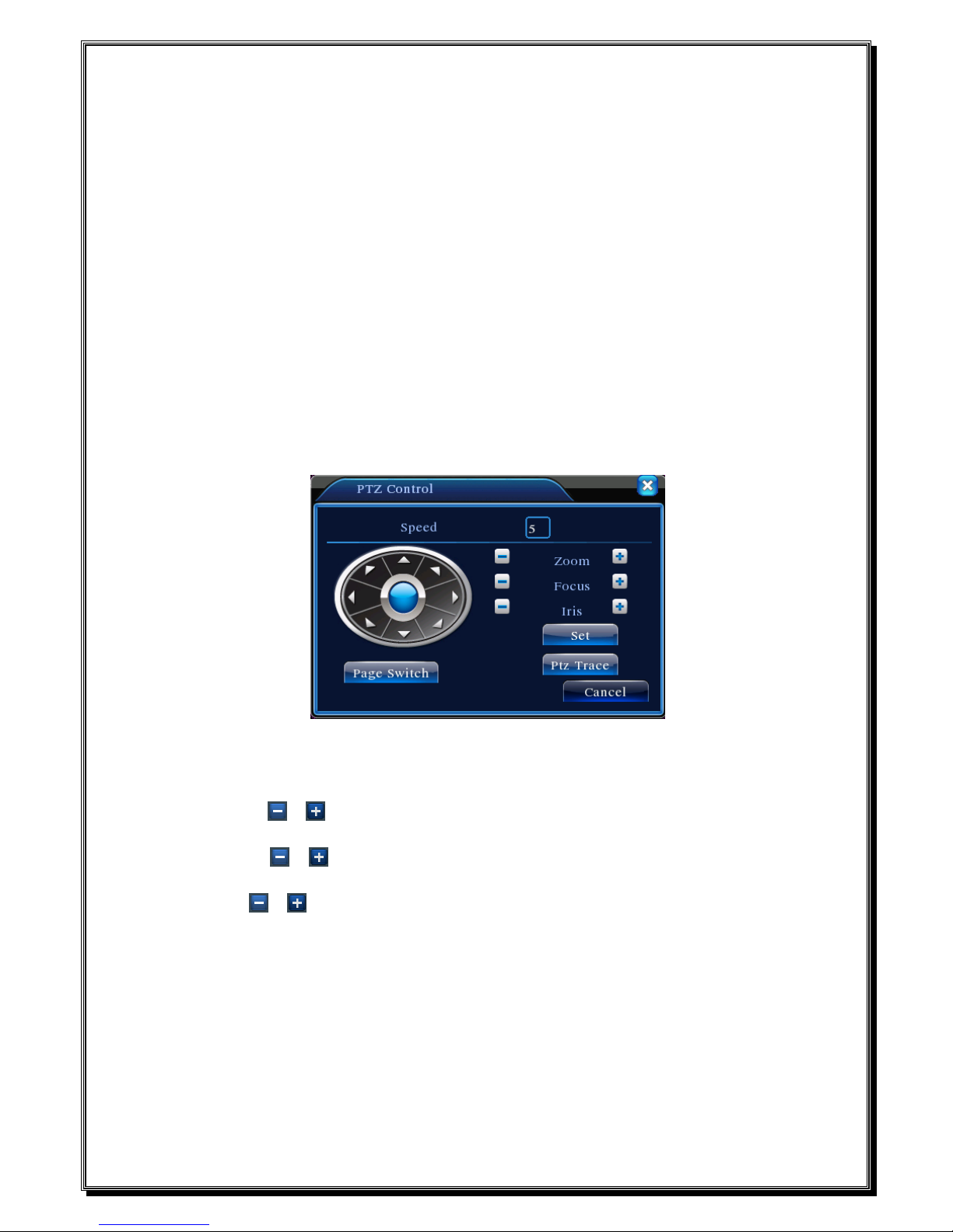
3.5.5 PTZ control
Operation interface is as followed. The functions include: PTZ direction control, step, zoom, focus,
iris, setup operation, patrol between spots, trail patrol, boundary scan, assistant switch, light switch,
level rotation and so on.
Note1. Decoder A(B)line connects with DVR A(B)line. The connection is right.
2. Click [main menu] >[system configuration] >[PTZ setup] to set the PTZ parameters.
3. The PTZ functions are decided by the PTZ protocols.
Picture 3.10 PTZ setup
【Speed】Set the PTZ rotation range. Default range: 1 ~ 8.
【Zoom】Click / button to adjust the zoom multiple of the camera.
【Focus】Click / button to adjust the focus of the camera .
【Iris】Click / button to adjust the iris of the camera.
【Direction control】Control the PTZ rotation. 8 directions control is supportive.(4 directions in Front
panel is supportive )
【High speed PTZ】Full-screen show channel image. Left press mouse and control PTZ to rotate
orientation. Left press mouse and then rotate the mouse to adjust the zoom multiple of the camera.
【Set】Enter the function operation menu.
【Page switch】Switch between different pages.
Page 20
Special functions:
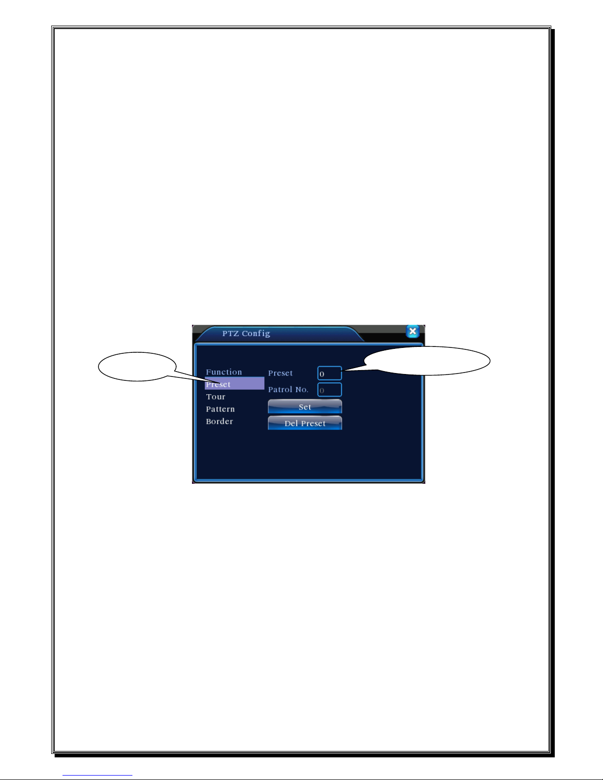
1、Preset
Set a location for the preset, calls the preset points, PTZ automatically turns to the setting
position
1)Preset option
Set a location for the preset, procedure is as follows:
Step1: in Picture 3.10, click the Direction button will turn into preset position , click the Settings
button to enter Picture 3.11.
Step 2: click the Preset button , then write the preset points in the input blank,
Step 3: click Settings button, return the Picture 3.10 Complete setup, that is the preset points and
preset position corresponds.
Clear Preset:Input preset points, click Remove button, remove the preset。
Picture 3.11 Preset Settings
2)Preset Point Calls
In Picture 3.10, click Page Shift button, enter PTZ control interface as shown in Picture 3.12. In
the input blank, write the preset points, then click Preset button, PTZ turn to the corresponding
preset point.
Preset button
Preset point input blank
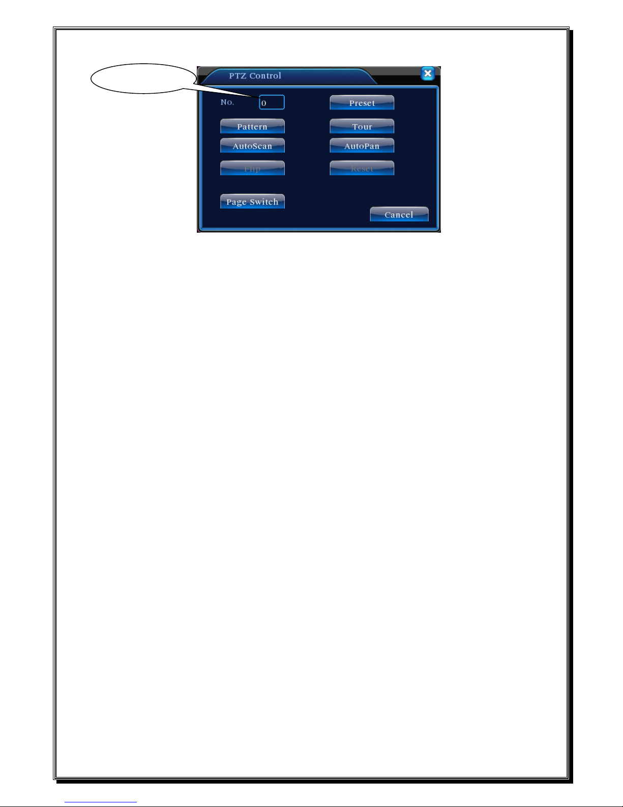
Page 21
Picture 3.12 PTZ Control
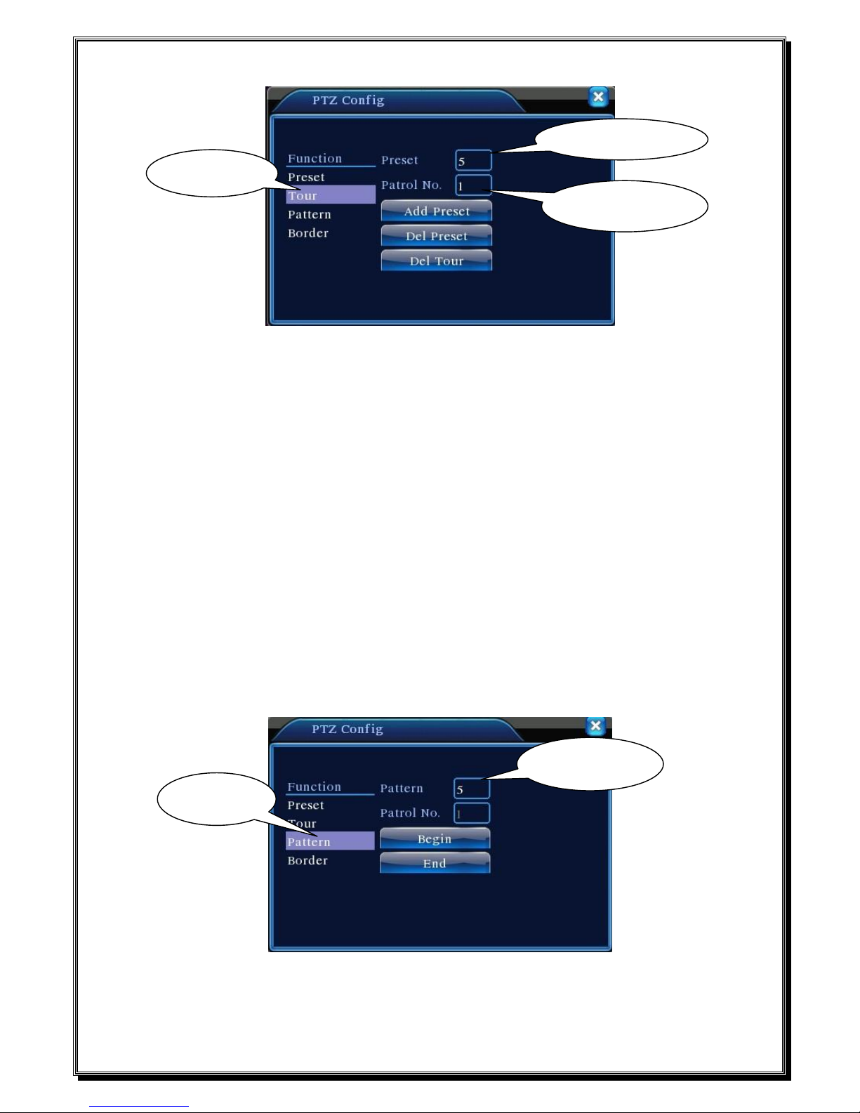
2、Cruise between Points
Multiple preset points connected cruise lines, call cruise between points, the PTZ run around on
the line
1)Cruise Between Points Settings
Cruise lines is connected by multiple preset points, setting procedure is as follows:
Step1: In Picture 3.10, the Direction key will turn PTZ to designated location , click Settings
button to enter Picture 3.13,
Step 2: click Cruise buttons, the write proper value into the Cruise Line and Preset Points blank,
then click Add Preset Points button, complete setting (also can add and delete cruise line which has
been set up)
Step 3: repeat step1 and step2 , until set out all the preset designated cruise lines。
Remove Preset:Please input preset value in the blank, click Remove Preset button, then
remove the preset points.
Remove Cruise Line:Input the number of cruise line, click Remove Cruise Lines button, then
remove the cruise lines set。
Value input blank
Page 22
Picture 3.13 Cruise Between Points Settings
2)The Calls of Cruise between Points
In Picture 3.10, click Page Shift button, enter PTZ control menu as shown in Picture 3.12. Please
input the number of cruise in the value blank, then click Cruise between Points button, PTZ begins to
work on the cruise line. Click Stop button to stop cruise.
3、Scan
PTZ also can work on the preset scan line repeatedly.
1)Scan setup
Step1:In Picture 3.10, click Setup button ,enter Picture 3.14;
Step2:Click Scan button,the input proper value in the scan value blank;
Step3:Click Start button, enter Picture3.10,here you can set the following items: Zoom、
Focus、Aperture、Direction and so on. Click Setup button to go back Picture 3.14;
Step4:Click End button to complete setup。Click the right button of the mouse to exit.
Picture 3.14 Scan Setup
Cruise Button
Cruise Line Blank
Preset Points Blank
Scan value blank
Scan Button
 Loading...