

Global Dryer GX-M, GX-C Owner's Manual
1 7/8
DISCONNECT POWER BEFORE INSTALLING
DESUNA LA ELECTRICIDAD ANTES DE HACER REPARACIONES
WARNING:
INSTALLATION INSTRUCTIONS
1. Remove cover by removing (2) tamper proof-screws using security wrench
supplied. Pull cover directly toward you. IMPORTANT: Save security wrench.
2. Dryers should be placed at least 2 feet (61cm) apart and at least 12” (30cm) from
washbasin. Do not install dryer over washbasin. Automatic dryers should be at least
18” (46cm) above any projection which may interfere with the operation of the automatic sensor.
Hold the backplate to the wall at the suggested mounting height. Measure from bot-
tom edge of backplate to the floor (Ref. Dimension “A”, Fig. 1):
CHILDREN
MEN WOMEN (depends on age) DISABLED
44” (112cm) 42” (107cm) 32 to 42” (81-107cm) 36” (91cm)
3. Mark the locations of the four mounting holes and the conduit entrance location on the
wall. (The conduit entrance is the proper hole diameter for 1/2 inch (13mm) conduit.)
4. Fasten the backplate to the wall where previously marked.
RECOMMENDATION:
Wood wall – No. 14 (M6) wood screws, 2 3/4” (70mm) long
Cement or brick – 1/4” (M6) stud expansion bolts, 3” (76mm) long
Hollow wall – 1/4” (M6) toggle bolts, length depends on wall thickness
5. Run service wire to the dryer location and connect to lead wires.
IMPORTANT: All units must be supplied with 3 wire service. Use No. 12 or 14 wire
as required by local electrical code. The ground wire must be connected to the dryer
ground screw. Unit must be installed by a qualified licensed electrician.
CONNECT TO A DEDICATED CIRCUIT NOT TO ExCEED 20 AMPS.
Dryers located in shower rooms or other wet locations should be equipped with
ground fault interrupter(s).
6. Carefully replace the cover using (2) tamper-proof screws supplied. Apply a bead of
caulk around edges of cover to wall.
GLOBAL DRYER
MFD by AMERICAN DRYER, INC.
12932 FARMINGTON ROAD, LIVONIA, MI 48150, U.S.A.
Telephone (734) 421-2400
GLOBAL DRYER LIMITED WARRANTY
All parts of the Gx-M/C models are warranted to the original consumer purchaser
to be free from defects in material and workmanship for a period of five (5) years or
three (3) years for Gx models from the date of purchase from manufacturer. Sensor
warranty three (3) years in the U.S.A. All models outside of the U.S.A., one (1) year
including sensor. We will replace FREE OF CHARGE, during the warranty period,
any warranted part which proves defective in material and/or workmanship under nor-
mal installation, use, and service, excluding normal wear. Replacement parts can be
obtained by returning the part, TRANSPORTATION CHARGES PREPAID. You must
notify factory prior to returning part or dryer. Any damage to this dryer as a result of
misuse, abuse, neglect, accident, improper installation, unauthorized repairs, or any
other use violative of instructions furnished by us, WILL VOID THIS WARRANTY. THIS
WARRANTY IS IN LIEU OF ANY AND ALL WARRANTIES, EXPRESS OR IMPLIED,
AND IS LIMITED TO THE REPLACEMENT OF DEFECTIVE PARTS ONLY. LABOR
CHARGES AND/OR DAMAGE INCURRED IN INSTALLATION OR REPLACEMENT
AS WELL AS ALL INCIDENTAL AND CONSEQUENTIAL DAMAGES CONNECTED
THEREWITH ARE EXCLUDED.
O
wner’s Manual
GX S
eries Hand Dryers
For InstallatIon or servIce
a
ssIstance Please call
(734) 421-2400 or
ImPortant: Have Model & Serial No. ready
model #______ serIal #______
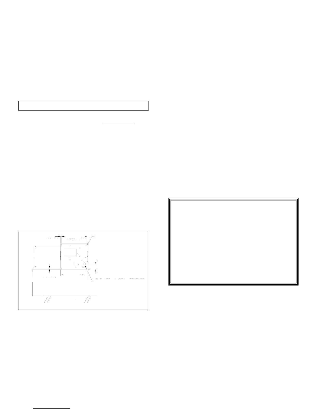
Figure 1 - dryer MouNtiNg
®
(48mm)
(208mm)
6 3/16
7/8 (22mm) DIA. IN-WALL
& SURFACE CONDUIT
ENTRANCES
MOUNTING HOLES FOR
1/4” (M6) DIA. SCREWS
(227MM)
8 15/16
7/16
(11mm)
7/16
(11mm)
“A”
8 7/16
(214mm)
FLOOR
SERVICE AND MAINTENANCE OF YOUR DRYER
GENERAL OPERATION
This dryer is activated by an infrared sensor. The dryer operates as long as hands are below
nozzle. There is a maximum 80 second running time with a safety over-ride feature, if hands
are not removed. Each component used in your dryer has been designed to provide years of
trouble-free service. However, if trouble should develop, it can normally be located by visual
examination. Removal or replacement of most parts, is simple and can be done without
special tools.
IF THE DRYER WON’T TURN ON:
Check electrical service, circuit breaker. Make sure proper voltage is being supplied to the
dryer. Check for loose or disconnected terminal to sensor. INCREASE sensitivity (
FIgure 3)
by using a flat-blade screwdriver and CAREFULLY turning the adjustment pot located on the
sensor CLOCKWISE 1/3 Turn MAx. Turn . If necessary, replace sensor.
IF DRYER WILL NOT SHUT OFF:
Make certain black foam is attached to lens and lens is clean. If damaged, replace.
DECREASE sensitivity (
FIgure 3) by CAREFULLY turning the adjustment pot located on
the sensor. Use a small flat-blade screwdriver. 1/3 Turn MAx. COUNTER-CLOCKWISE. If
necessary, replace sensor.
IF COLD AIR IS COMING FROM THE NOZZLE:
Turn off breaker for 30 seconds to reset thermostat. If required. remove the cover and vent,
check the heating element. If the element is broken or burned out, replace it.
IF NO AIR IS COMING FROM THE NOZZLE AND HEATING ELEMENT GLOWS:
Remove the cover and check to see that the fan revolves freely. Check and replace motor,
if required.
FOR ANY OTHER PROBLEM, CONTACT FACTORY FOR ASSISTANCE.
CLEANING - DO NOT spray cleaning solvents thru dryer vents. DO NOT use abrasive,
chlorinated, or highly alkaline cleaners. DO NOT use oil based cleaners.
SEMI-ANNUALLY remove the cover and clean all lint and dust from the mechanism, inside
of cover, and plastic window.
Clean cover with a mild soap or detergent and warm water, using a soft cloth or sponge.
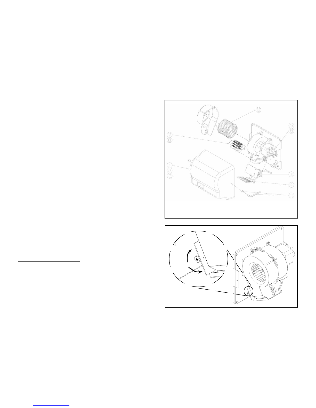
PARTS LIST FOR YOUR DRYER (Figure 2)
ITEM PART NO. DESCRIPTION
1 GX202 COVER, WHITE ABS
(MUST SPECIFY DRYER MODEL #)
2 GX202-M COVER, WHITE STEEL
(MUST SPECIFY DRYER MODEL#)
3 GX202-C COVER, CHROME PLATED STEEL
(SPECIFY DRYER MODEL #)
4 GX212 VENT ASS’Y W/ LENS AND FOAM GASKET
5 GX216 MOTOR, 110-120V INCLUDES BLOWER WHEEL (GX1)
6 GX217 MOTOR, 208-240V INCLUDES BLOWER WHEEL (GX3)
7 GX218 HEATING ELEMENT 110-120V (GX1)
8 GX220 HEATING ELEMENT 208-240V (GX3)
9 GX228 BLOWER WHEEL
10 GX239 SENSOR COMPLETE, 110-240 VOLT
11 GB232 TAMPER-PROOF SCREWS & SECURITY WRENCH
Figure 3 SeNSitivity adjuStMeNt
+
-
Figure 2 - Exploded view
DISCONNECT POWER BEFORE INSTALLING
DESUNA LA ELECTRICIDAD ANTES DE HACER REPARACIONES
WARNING:
 Loading...