

Page 1

®
Viceversa Bridges
Installation Manual
2011
OHSAS 18001:2007
CGSB #0HS-009
Visit us on the Internet at globalcontract.com • (416) 739-5000
ISO 9001:2008
CGSB #94613-5
ISO 14001:2004
CGSB #EMS-040
Global Contract Inc. 565 Petrolia Road
North York, Ontario, M3J 2X8
Page 2
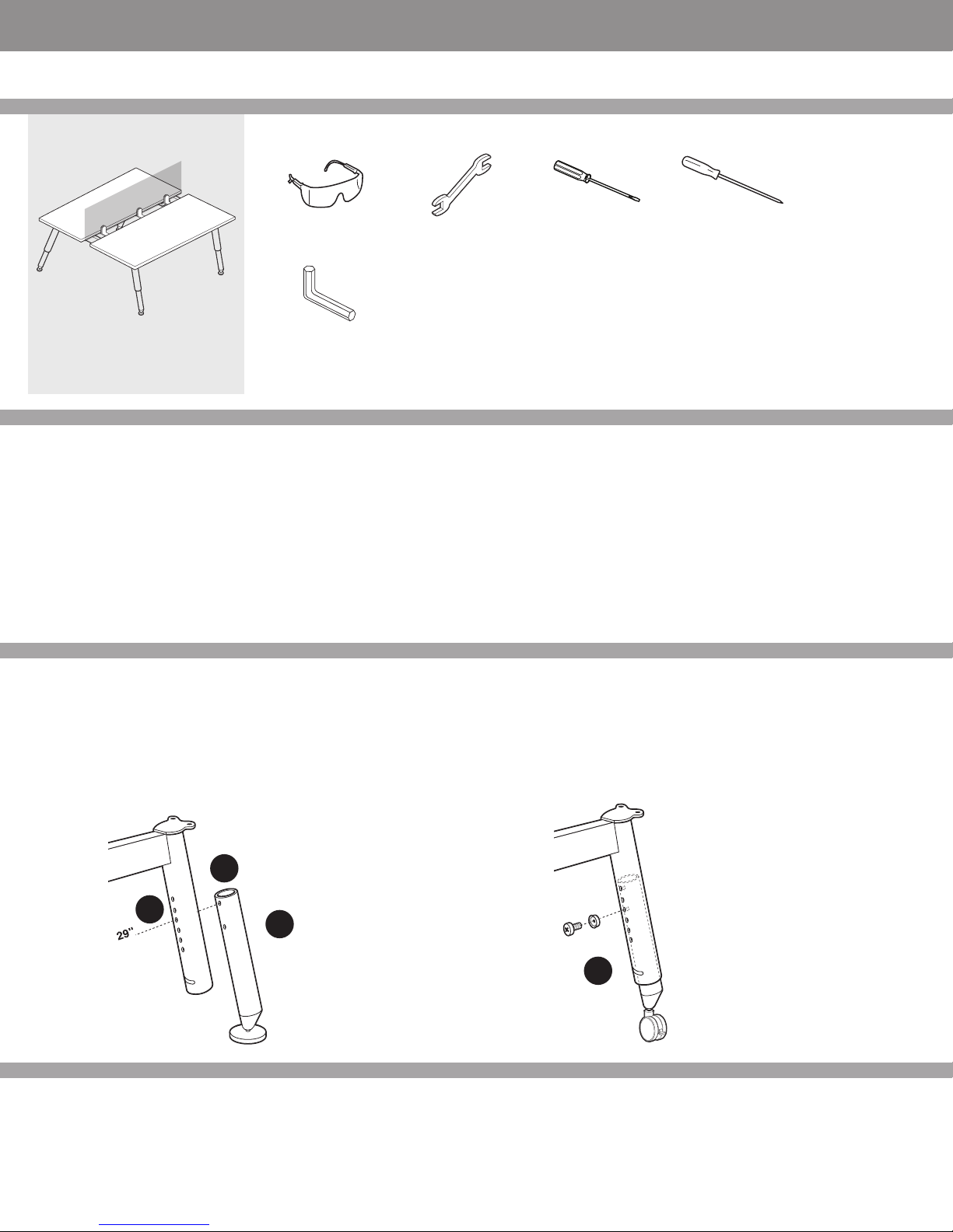
Required Tools:
Safety Glasses
Rubber Mallet
Flathead Screw
driver
Actuator
Pliers
10 mm Hex Bit
Phillips Bit
T-25 Torx Bit
Bit Adaptor /
Handle
Socket Wrench
13 mm Socket
GLOBALContract
INSTALLATION GUIDELINES
Bridges
Required Tools
Safety Glasses
Allen Key
Viceversa® Bridges Installation Sequence
STEP 1: LAYOUT ORIENTATION
Orient the layout plan within the installation area, determine the location of table
assemblies, power source and main storage components; establish the highest point
on the floor.
STEP 2: SUPPORTING STRUCTURE - legs, supporting beams
Identify type and size of required components and position them in accordance with
layout plans. Proceed with connecting legs and structural beams (see the following
pages for detailed instructions). Make sure that all rails are leveled and securely connected before proceeding with installation of work.
Wrench Flathead Screwdriver Phillips Screwdriver
STEP 4: ACCESSORIES - task and paper organizers
Determine type and location of accessories fitting into either top or bottom of the rail
as specified in floor plans. Proceed with installation of accessories.
STEP 5: STORAGE
STEP 6: ELECTRICS and DATA / COMMUNICATION - cable routing; cable management
Connect power feed harness to building power supply; check circuit assignments and
functionality of power delivery at each duplex receptacle.
• Spring 2011
STEP 3: WORKSURFACES
Supporting Structure Height Adjustment
Set the legs to desired height.
The inner leg has two threaded holes.
STEP 1: The top threaded hole is typically used to secure legs with levelers.
STEP 2: The lower threaded hole is used for securing legs with casters.
1
3
2
STEP 7: WALK THROUGH / INSTALLATION INSPECTION
STEP 3: If the desired top surface height is 29” from the floor, for instance, and the
table structure is to be on levelers, align top threaded hole in the inner leg (1) with the
fourth hole in the table leg (3) as illustrated. When installing legs on casters, align the
lower (2) threaded hole in the inner leg with the same fourth hole (3) in the table leg
and secure with provided screws.
STEP 4: The height adjustment screws must be only used with the provided,
translucent cup/washer.
4
Please contact your Global Contract Service Representative at 416-739-5000 for
any questions or concerns.
NOTE: Any alterations to listed components will void the manufacturer’s warranty.
The manufacturer will not be responsible for any damage or bodily harm caused
by alterations in accordance with national or local electrical codes and manufac-
Page • globalcontract.com1
turer’s specifications. In accordance with the manufacturer’s policy of continual
product improvement, the product presented in this document is subject to
change without notice or obligation.24
Page 3
GLOBALContract
3
4
Supporting Structure Height Adjustment
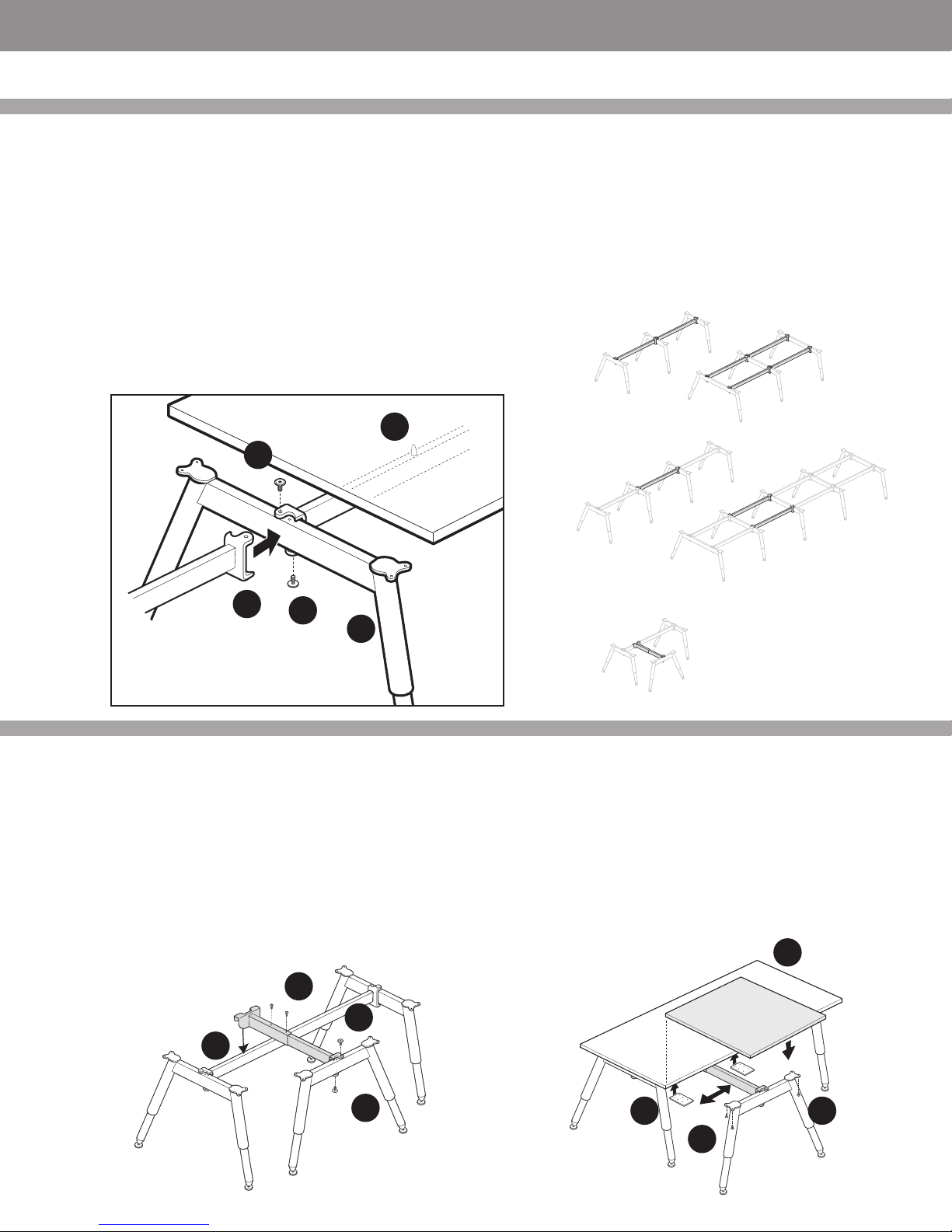
Legs are connected with supporting beams. There is one beam for a single
line of tables while two beams connect back-to-back table structures.
There are three types of beams whose application principles are common to building
support for single-line and back-to-back table assemblies: Standard Beam, Interconnect Beam and Telescopic Beam
STANDARD BEAM
Designed to bridge two or three legs to form support for a single table, or for two
adjacent table assemblies.
INTERCONNECT BEAM
Designed to bridge space between two table assemblies. Because the interconnect
beam is 4” longer than the standard beam, it spreads supporting legs apart so that
they can be shared by adjacent worksurfaces. A typical, multiple surface table run
begins with a standard beam, continues with required number of interconnect beams
and ends with a standard beam at the opposite end of the run.
• Spring 2011
INSTALLATION GUIDELINES
To connect a beam to a leg, identify the correct type (Standard or Interconnect) first in accordance with your desired table configuration.
STEP 1: Position beam’s end bracket over leg’s horizontal, rectangular tube.
STEP 2: Space cord bumpers along beam. A 72” beam should have 2
STEP 3: Secure top and bottom bracket ends with two supplied screws.
Level the whole assembly.
STEP 4: Install worksurfaces and secure with supplied screws by proceeding from the
central, shared leg to the outside of the assembly in both directions.
STANDARD BEAM
2
3
INTERCONNECT BEAM
1
3
4
Legs and Beams
TELESCOPIC BEAM
Designed to provide support for worksurfaces perpendicularly connected to a primary
table run. The telescopic beam is connected to the leg’s horizontal, rectangular tube
on one side, while the opposite side is secured off module to the perpendicular,
central beam and can be adjusted to accommodate 24” and 30” deep primary
worksurfaces.
STEP 1: Position beam’s end bracket over leg’s horizontal, rectangular tube.
STEP 2: Secure top and bottom bracket ends with two supplied screws.
STEP 3: Adjust the length of the telescopic beam in accordance with the depth of
primary worksurface.
3
3
2
4
4
TELESCOPIC BEAM
STEP 4: Position end bracket of the telescopic beam over the primary, perpendicular
beam. Level the whole assembly.
STEP 5: Install primary worksurface.
STEP 6: Secure the secondary worksurface to legs first.
STEP 7: Adjust the secondary worksurface/telescopic beam position.
STEP 8: Secure the worksurfaces with flat brackets.
5
1
8
6
7
•Pageglobalcontract.com 2
Page 4
GLOBALContract
GENERAL INFORMATION
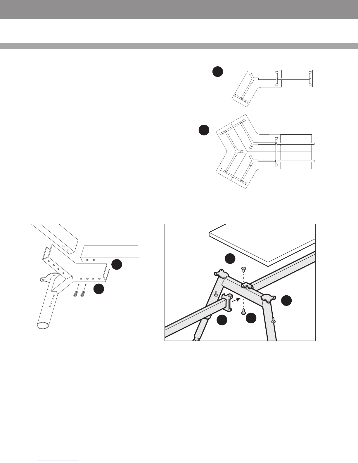
120º Beam Support
Designed to connect “A” frame legs with 120º “corner” leg to form support for a
single table, or for adjacent table assemblies.
• January 2010
The integrated 120ª beam bracket allows for the beam to be mounted in two positions:
A) end of run leg placement
B) shared leg placement
Identify the desired leg position (A or B)
STEP 1: Align two mounting holes in beam with two holes in the integrated 120º
beam bracket. Position beam’s end bracket over leg’s horizontal, rectangular tube.
STEP 2: Secure both beams to the integrated 120º beam bracket with four supplied screws.
STEP 3: Position beam’s end bracket over leg’s horizontal rectangular tube.
STEP 4: Secure top and bottom bracket ends with two supplied screws.
STEP 5: Level the whole assembly.
STEP 6: Install work surfaces and secure with supplied screws by proceeding
from the central, 120º leg to the outside of the assembly in both directions.
NOTE: 24” deep worksurfaces are mounted centrally on top of the table structure. 30” deep worksurfaces are mounted off center, with a longer overhang
facing the user.
A
B
4
1
2
6
3
4
Page • globalcontract.com3
Page 5

GLOBALContract
3”
1”
Sliding Return
Ensure that back-to-back table installation is complete, level and structurally
sound. Installation of Sliding Rail requires a special degree of accuracy of work
surface alignment. Failure to do so may result in binding of the sliding mechanism on the Sliding Rail.
Establish range of the Sliding Return.
STEP 1: Mark a line 3” in from (and parallel with) the front edge of work
surface.
STEP 2: Position the Sliding Rail and secure it with supplied screws. Always proceed from the second hole, leaving the first hole for installation of the Rail stop.
NOTE: the pair of screws provided to secure the rubber rail stops at either
end of the rail are longer than the screws for securing the rail to the work
surface. Do not use these longer screws to secure the rail as the screws may
penetrate through the top of the work surface.
STEP 3: Secure leg support bracket to a leg frame with supplied machine
screws (wide flat allen head).
STEP 4: Place the Sliding Return work surface upside down on a clean surface.
Secure the leg assembly to the work surface with supplied wood screws.
Ensure that the legs are set to the same height as the legs supporting the rest
of the table installation.
• January 2010
GENERAL INFORMATION
3”
1
2
STEP 5: Place eight supplied rubber spacers over pre-drilled holes. If you are
converting an existing Return work surface to a Sliding Return, mark a line 1”
in from (and parallel with) the edge of the Return work surface.
STEP 6: Align supporting brackets with rubber spacers / pre-drilled holes (or
the marked line) and secure both brackets with supplied wood screws.
NOTE: In order to ensure a smooth sliding action, both brackets must be
perfectly perpendicular to the edge of the return work surface.
STEP 7: Slide the two glide blocks with bushings carefully onto the Rail as
illustrated.
STEP 8: This step requires two people:
While the leg supported side of the Return rests on the floor have an assistant
position supporting brackets under sliding glide blocks, align the holes and
gently drive in two machine screws (metric M6 as provided). Do not tighten. In
the same manner secure the second bracket to the second glide block and test
smoothness of the slide. Carefully tighten all four metric screws while repeatedly testing smoothness of the slide. If the return binds on the Sliding Rail, then
your support bracket(s) are not perpendicular to the rail - causing the
glide blocks to jam.
STEP 9: Secure rail stops to both ends of the rail with supplied (longer) srews
to prevent disengagement.
4
4
3
4
6
1”
5
7
9
8
•Pageglobalcontract.com 4
Page 6
GLOBALContract
INSTALLATION GUIDELINES
Table Supports
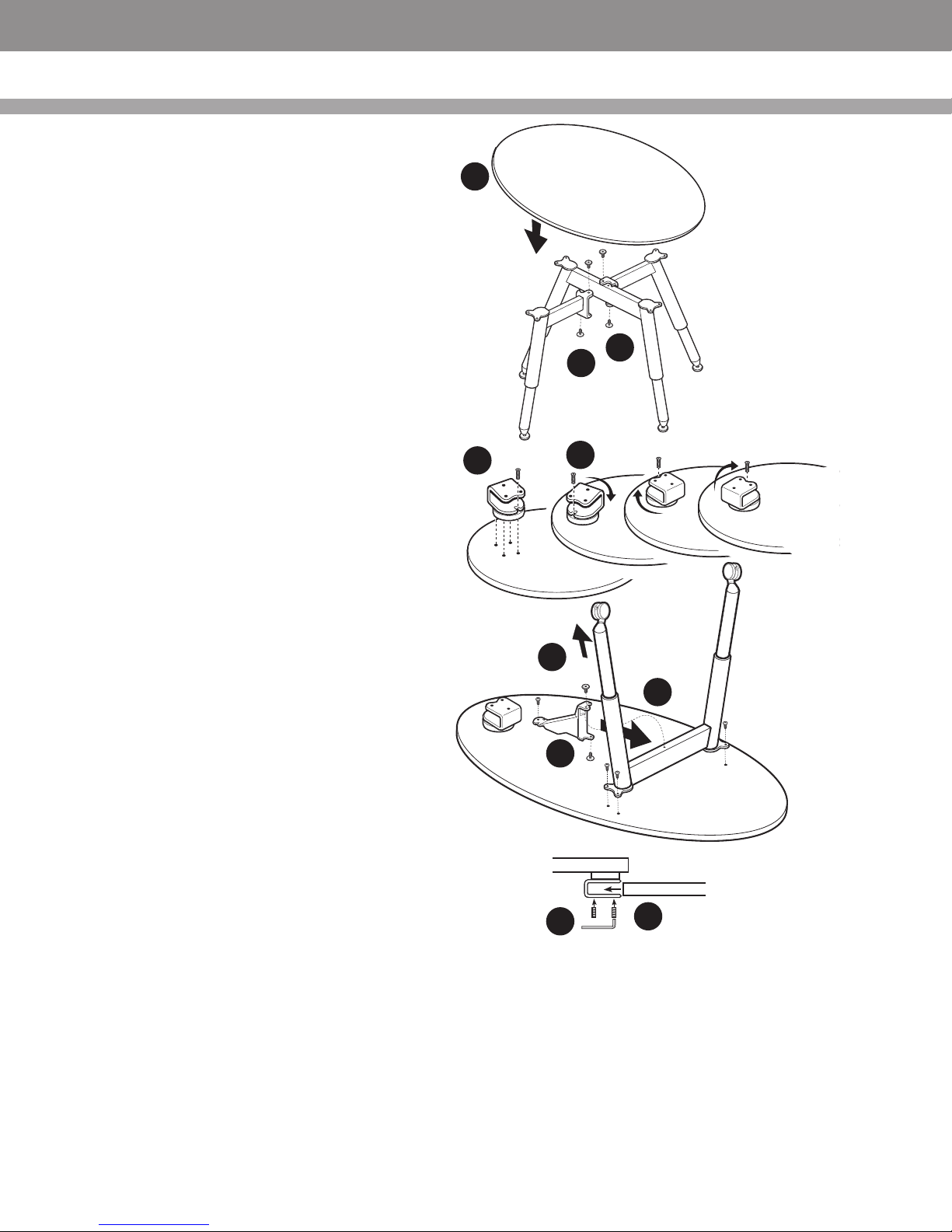
ROUND TABLE SUPPORT
Round table structure consists of one main leg and two individual legs.
• Spring 2011
STEP 1: Position each individual leg’s end bracket over the main leg’s horizontal,
rectangular tube.
STEP 2: Secure top and bottom bracket ends with the supplied screws. Level the
whole assembly.
STEP 3: Install round worksurface.
PIVOTING TABLE SUPPORT
Round and oval pivoting table structure consists of one main leg, leg bracket and a
pivoting clamp. Place oval worksurface upside down on a clean surface.
STEP 1: Align clamp over pre-drilled holes.
STEP 2: Rotate pivoting clamp over disc to reveal screw holes and drive in 4 supplied
screws (the clamp must be rotated 90 degrees to reveal the next screw hole).
STEP 3: Secure leg support bracket to leg with two screws.
STEP 4: Secure leg support bracket/leg assembly to worksurface with five supplied
screws.
STEP 5: Increase leg height by 2” (two increments) to compensate for the height of
the pivoting clamp.
Invert the table assembly.
STEP 6: Position table with pivoting bracket over the edge of the primary table as
illustrated.
3
1
2
1
2
STEP 7: Tighten the set screws of the pivoting clamp, securing it to the primary table.
ROUND / OVAL TABLE
5
4
3
PRIMARY TABLE
7
6
Page • globalcontract.com5
Page 7
GLOBALContract
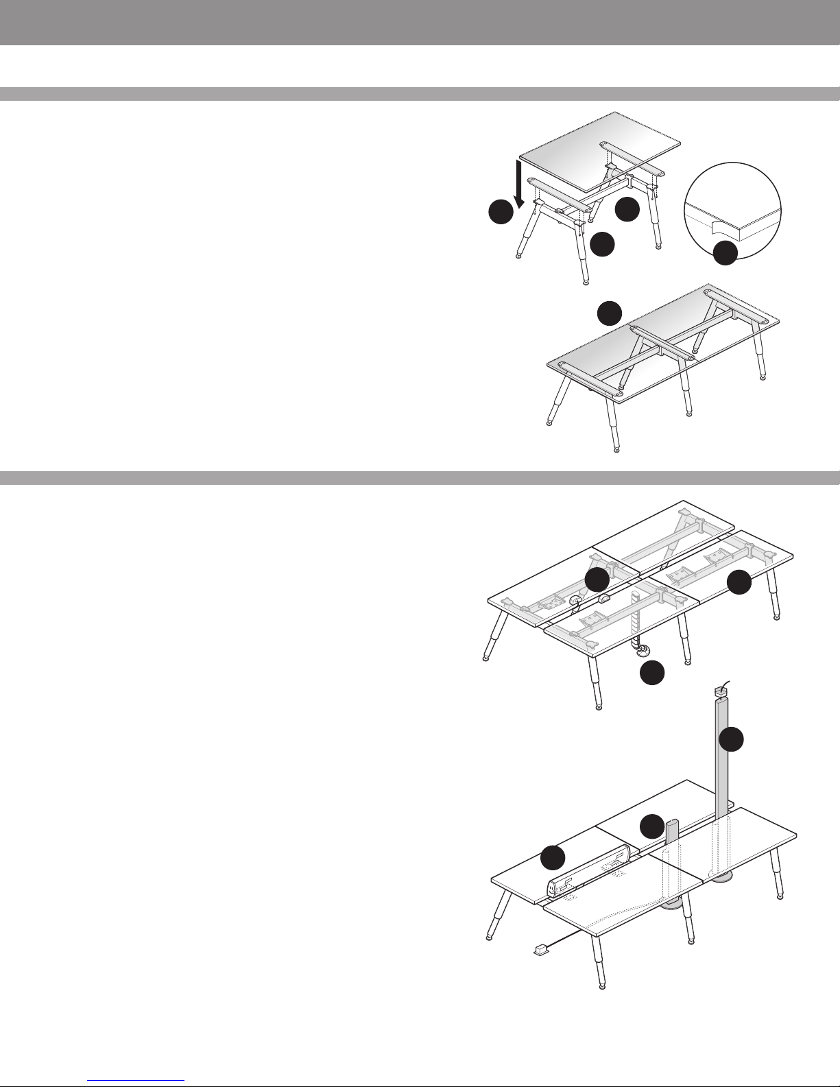
Cantilevers for Glass Tops
Cantilever/Glass Tops
Designed to provide support to either single or multiple glass work surfaces.
Size of the cantilever corresponds with the depth of glass worksurface (24” and 30”).
Begin by assembling table leg/beam structure as described previously and level the
complete support assembly.
STEP 1: Position the glass top cantilever over table leg so that threaded
pins which are welded to the bottom of each cantilever fit through the four mounting
holes in the leg.
• Spring 2011
INSTALLATION GUIDELINES
3
1
STEP 2:Secure each glass top cantilever with four supplied acorn nuts.
STEP 3:Position the glass top on the structure while ensuring that all clear
contact pads are in place.
STEP 4:When installing multiple glass tops on a shared leg/cantilever support assemblies, ensure that each adjacent glass top edge is placed in the centre of each shared
cantilever, resting on two clear contact pads.
STEP 5:Position the first glass top. Apply transparent, adhesive bumper
on the edge facing the adjacent glass top. The transparent bumper protects the two
glass tops from rubbing and chipping.
Complete the installation by placing the second glass top on the supporting structure.
Cable Management and Electrics
At the basic level, table and floor based office equipment is serviced by a wall or floor
power supply. As the operation grows, there might be a need to organize excessive
cable clutter.
Cable tray (1) fits over the Standard or Interconnect Beams and cables are simply
coiled into it. As many as 3 Cable Tray will fit on a 60” beam.
Cable Snake(2) installed in proximity of floor monument and worksurface grommet
manages vertical cable clutter.
Table clamped, single circuit power and date “Mini-Adapt” modules (3) deliver
services to desk height, while tapping into wall or floor power supply. Again, the
excessive cables can be managed with Cable Trays.
Viceversa® Power Tower (4) and Power Pole (5) deliver up to four circuits either from
the floor or ceiling power sources. When combined with Mini- Adapt modules, this
power could be distributed further horizontally, at desk level.
2
5
4
3
1
2
Doc-it rail (6) can be installed between back-to-back tables for extended desk height
power/data distribution.
5
4
6
•Pageglobalcontract.com 6
Page 8
GLOBALContract
INSTALLATION GUIDELINES
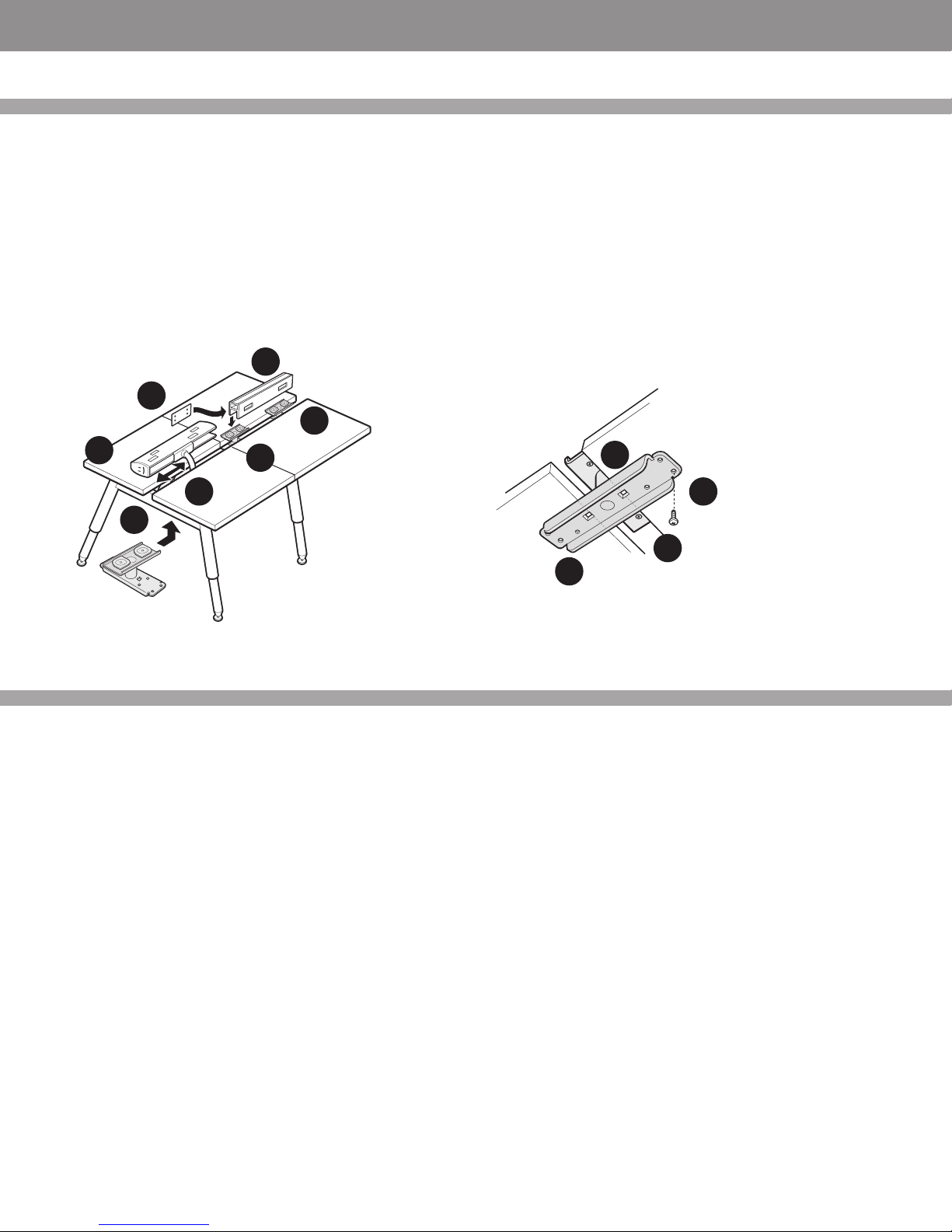
Doc-it Powered Rail
Ensure Back-to-Back table installation is perfectly level. Refer to “Doc-it Installation
Manual” to assemble the first rail, including duplexes, internal junction box and base
power feed.
STEP 5: Install remaining support brackets. Rail supporting brackets can be shared by
two rails. In this case, the central bracket will be shared equally between both adjacent
worksurfaces.
• Spring 2011
STEP 1: Place this subassembly on a table, exactly in desired location.
Doc-it support brackets attach to the Doc-it rail anywhere along its’ bottom. Anywhere
except the optional base feed location.
STEP 2: Establish location of the first support bracket (in this case between the floor
power feed and the end cap).
STEP 3: Bolt the first bracket to the underside of the worksurface.
STEP 4: Use the two rectangular openings in the brackets to centre the bracket exactly
in between back-to-back worksurfaces.
6
8
5
1
5
2
3
STEP 6: Remove rail covers, set the first rail beams on top of the support brackets.
STEP 7: Secure the first beam by rotating cam locks and by tightening the bottom
screws.
STEP 8:Complete the Doc-it installation (rail connectors, adjacent rail, power distribution system, harnesses, junction boxes and duplexes, end caps, data/communications
terminals, rail accessories and rail covers).
Please refer to “Doc-it Installation Manual” for detailed instructions.
7
3
7
4
Power Trough
NOTE: Install dividers, storage and table top accessories prior to proceeding with the
installation of power trough.
A) SUPPORTING STRUCTURE
Identify length and location of required Power Troughs and position them in accordance with lay-out plans. Install brackets on Power Troughs. Make sure that all
Power Troughs are securely connected before proceeding with installation of electrical
components.
B) ELECTRIC COMPONENTS
Identify type and location of required electrical components and position them in
accordance with lay-out plans. Secure Power Feed to the Power Trough brackets
(ensure that the liquid tight whip is long enough to reach the power source / floor
monument. Proceed with connecting Power Distribution Assemblies and Jumper
Harnesses on the ground, just below their future location. Install Duplex Receptacles
as specified. Secure interconnected electrical components to Power Trough.
C) DATA/COMMUNICATION
Arrange cables below their future location into bundles under the tables. Install cable
terminals and snap Terminal Plates into the openings in the middle of Power Trough.
Proceed from one side of the table assembly, lift cable bundles and secure them to the
Power Trough with extruded Data Cable Manager.
D) CONNECT TO THE BUILDING POWER SUPPLY
It is recommended that the connection to the building power supply be made under
the supervision of a licensed electrician and according to applicable codes and regulations. Connection to the building power supply must be done by a licensed electrician.
Do not connect or disconnect components while the system is under load. Disconnect
the main power before servicing or reconfiguration.
E) WALK THROUGH / INSTALLATION INSPECTION
Page • globalcontract.com7
Page 9
GLOBALContract
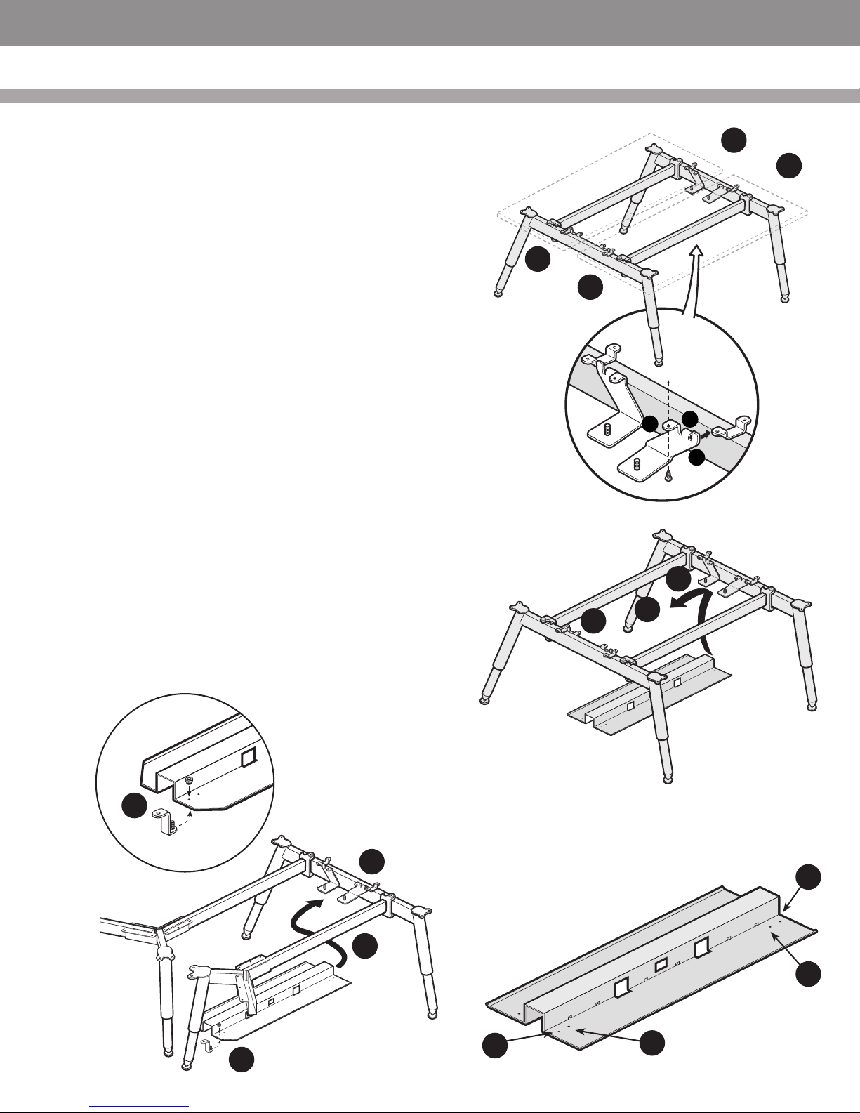
Power Trough Supporting Structure
STEP 1: Install four brackets (two pairs of left and right brackets are required).
• Spring 2011
INSTALLATION GUIDELINES
Ensure that tab “A” fits over the rectangular VV2DL leg horizontal cross member.
Use tab “B” to locate the bracket against the VV2DL leg worksurface bracket
as illustrated.
Secure each bracket by driving supplied screws through tab “C” into the bottom of
the worksurface.
STEP 2: Install Power Troughs. Power troughs are provided with 4 pairs of
mounting holes to accommodate various VV2DL leg positions.
Use pair of mounting holes “B - B” to secure Power Trough to a single assembly of two back-to-back tables or to a back-to-back table assembly at the
beginning of a multiple table run. (Single table assemblies and tables at the
beginning of a table run employ standard-length support beams).
Use the pair of mounting holes “A - A” to secure Power Trough to back-to-back
tables in the middle of a multiple table run. (Tables in the middle of a multiple
table run employ extended-length support beams. The legs are wide apart,
shared between adjacent back-to-back table assemblies.)
STEP 3: Slide Power Trough loosely over the brackets (first on one end, then on
the opposite end of the Power Trough).
STEP 4: Position the Power Trough over the brackets. Ensure that threaded
studs protrude through the holes in the Power Trough.
120º Power Trough
120º Power Troughs are secured to tables with two types of brackets: the standard
trough-mounting brackets on one side )the same, above described rules apply: A
position for shared application; B position for end of a run application) and narrow
”Z” brackets securing the opposite side of the Power Troughs in the proximity of the
120º ‘corner’ leg.
STEP 5: Preassemble “Z” brackets and power Troughs: Thread the threaded stud
through the Power Trough as illustrated. (Notch in the front edge of the Power
Trough prevents the “Z” bracket from rotating).
1
1
1
1
A
C
B
4
3
4
Follow steps 3 and 4 to install the opposite side of the 120º Power Trough.
5
5
4
A
3
B
A
B
•Pageglobalcontract.com 8
Page 10
GLOBALContract
INSTALLATION GUIDELINES
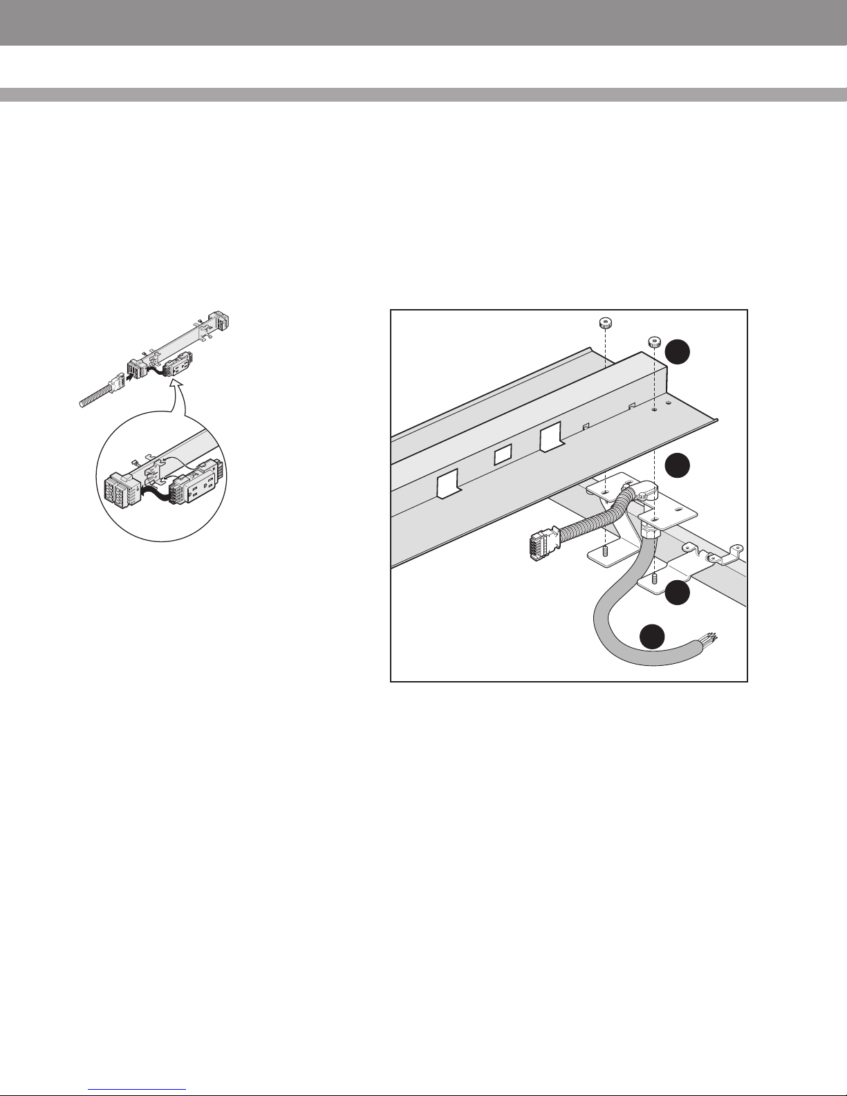
Power Trough Electric Components
Identify type and location of required electric components and position
them in accordance with lay-out plans.
STEP 5: Secure Power Feed to the Power Trough brackets (ensure that the
liquid tight whip is long enough to reach the power source / floor monument).
STEP 6: Lift the Power Trough on one side and rest the Power Feed mounting
bracket on top of the Power Trough brackets.
STEP 7: Lower the Power Trough so that the Power Feed bracket is sandwiched
between the Power Trough and Power Trough supporting brackets; ensure that
threaded studs protrude hrough the holes in the Power Trough.
STEP 8: Secure all Power Troughs with supplied knurled thumb nuts.
STEP 9: Connect Power Distribution Housings and Jumper Harnesses on
the ground, just below their future location.
NOTE : There is an arrow and a letter “N” on each Power Distribution Housing
and on every Jumper Harness referring to the correct position in relation to
each other.
STEP 10: Install Duplex Receptacles as illustrated, with circuit numbers in accordance with the electrical plans.
• Spring 2011
8
7
6
5
Page • globalcontract.com9
Page 11
GLOBALContract
Power Trough Electric Components : Continued
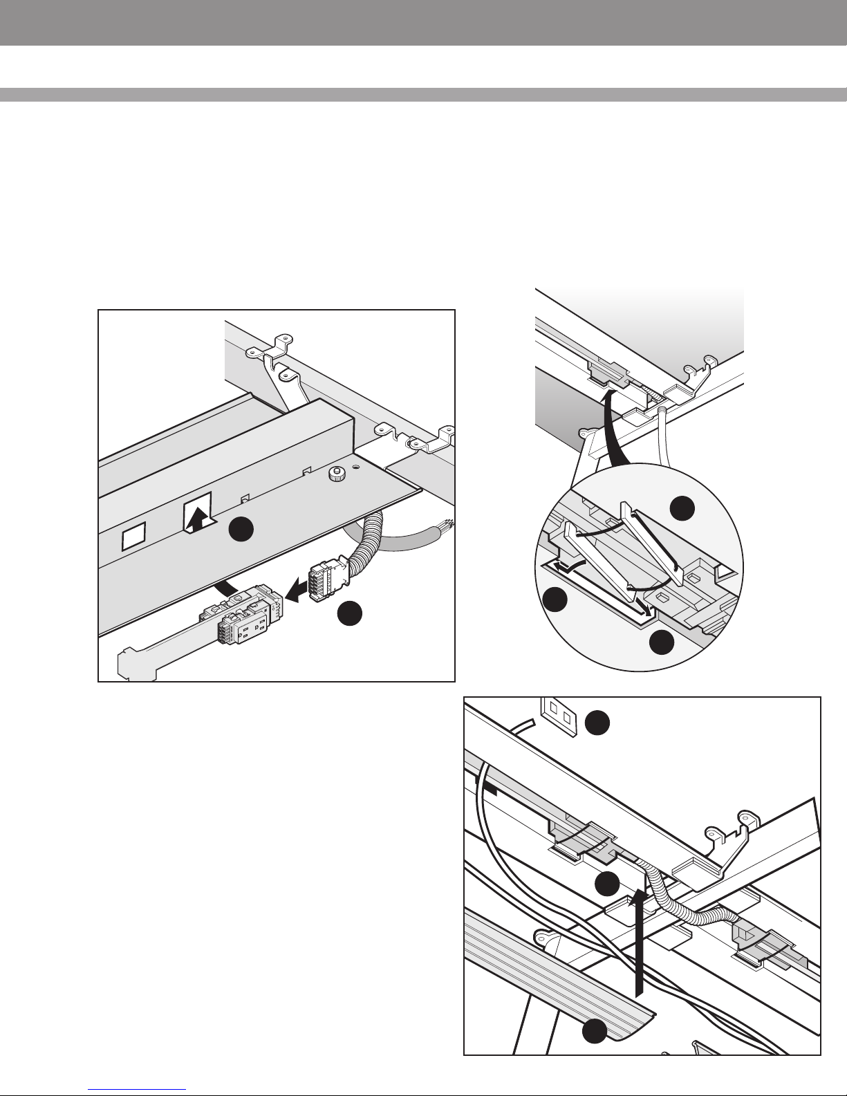
STEP 11: Secure interconnected Electrical Components to Power Troughs:
Proceed from the Power Feed by connecting its harness to the Power Distribution Housing.
NOTE: There is an arrow and a letter “N” on each Power Distribution Housing
and every Power Feed referring to the correct position in relation to each other.
• Spring 2011
INSTALLATION GUIDELINES
STEP 15: Repeat steps 13 and 14 under the opposite Duplex Receptacle. Proceed
to the opposite end of Power Distribution Housing.
Ensure that all electrical components are interconnected and secured to Power
Troughs.
Connect Power Feed to the building power supply.
STEP 12: Insert assembled Electrical Components into the Power Trough from
the bottom. Ensure that all four Duplex Receptacles are located in their designated openings.
STEP 13: Insert Power Distribution Housing Lock into the gap between Power
Trough and the bottom of the Duplex Receptacle.
STEP 14: Slide back to engage the opposite end as illustrated.
12
NOTE: There must be only one power feed entry into each cluster of harnesses.
WARNING! It is recommended that installation of the wiring system be made under the supervision of a licensed electrician in accordance with applicable codes
and regulations. Connection to the building power supply must be done by a
licensed electrician. Do not connect or disconnect components while the system
is under load. Disconnect the main power before servicing or reconfiguration.
15
11
Organize data/communication cables on the ground just below their future
location.
STEP 16: Thread cable through data/communication opening (located in the
middle of each Power Trough). Connect terminals and snap terminal plate into
data/communication opening.
STEP 17: Capture cable bundles in the extruded Data Cable Manager trough
STEP 18: Snap Data Cable Manager Trough into the bottom of Power Trough.
Ensure that Data/communication Troughs are securely engaged with all tabs at
the bottom of Power Troughs. (Refer to actual part)
14
13
16
18
17
•Pageglobalcontract.com 10
Page 12
GLOBALContract
1
INSTALLATION GUIDELINES
Glazed Table Divider
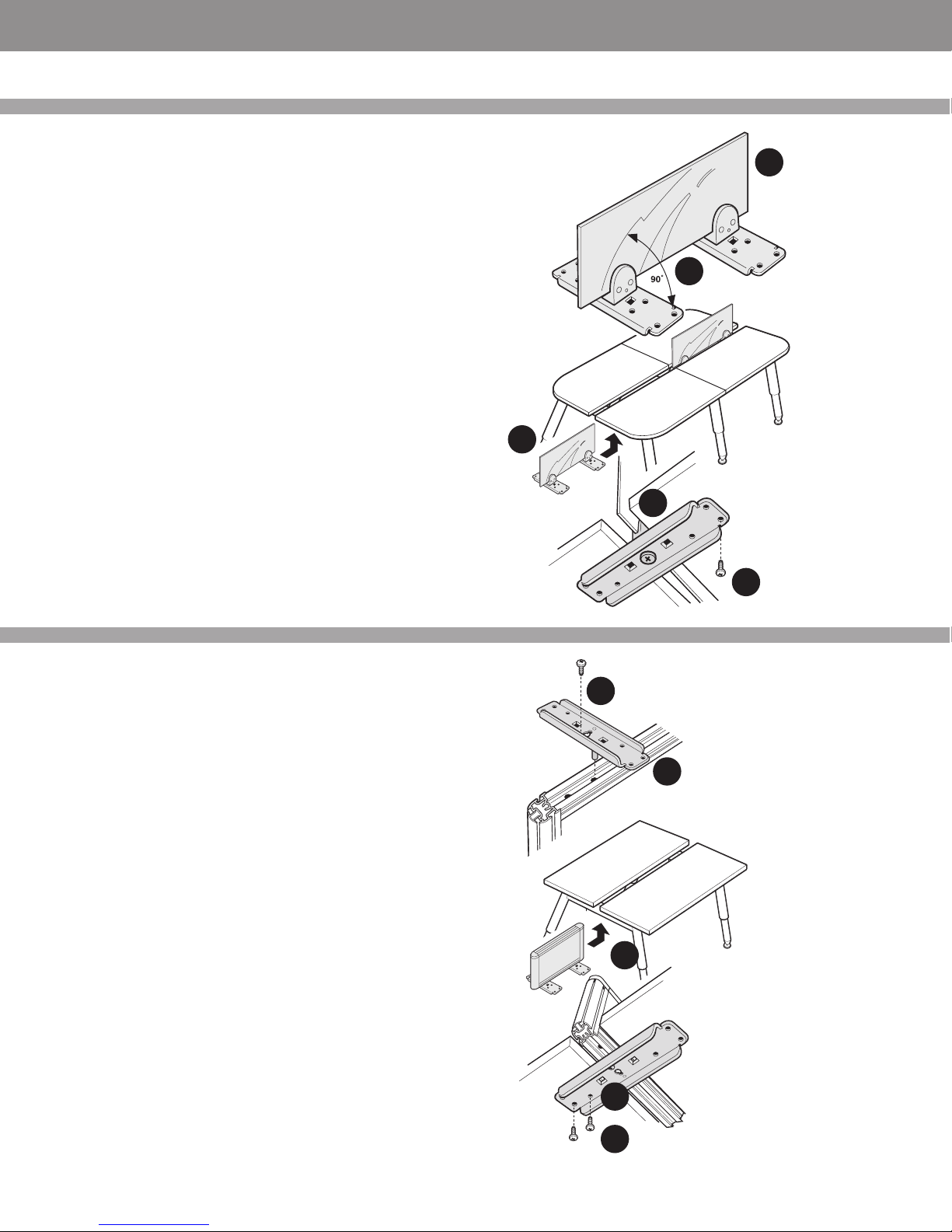
36”, 42” and 48” wide dividers have 2 brackets, all others have 3.
• Spring 2011
STEP 1: Install mounting brackets along the bottom edge of the divider (two upper
screws provide “clamping power” while the central set screw adjusts clamping angle).
STEP 2: Ensure that the brackets are perfectly perpendicular to the divider.
STEP 3: Bring the divider/bracket assembly from the bottom, up through
the gap between the tables. Have two people holding it in desired location, while a
third person secures the brackets to the bottom of the worksurfaces.
STEP 4: Use the two rectangular openings in the brackets to centre the bracket exactly
in between back-to-back worksurfaces.
STEP 5: Bolt the brackets to the underside of worksurfaces.
Once installed, ensure that the divider is perfectly vertical. Check and adjust mutual
alignment if there are more dividers installed.
1
2
3
4
5
Fabric Table Divider
Install mounting brackets into the bottom of Fabric Table Divider. 36”, 42” and 48”
wide dividers require 2 brackets, 54” and 60” wide dividers require 3.
STEP 1: Slide bracket rods into the holes in the bottom of fabric dividers.
STEP 2: Ensure that the brackets are perfectly perpendicular to the divider and secure
each bracket with supplied, self drilling screws.
STEP 3: Bring the divider/brackets assembly from the bottom, up through the gap
between the tables. Have two people holding it in desired location while a third person
secures the brackets to the bottom of the worksurface.
STEP 4: Use the two rectangular openings in the brackets to centre the bracket exactly
in between back-to-back worksurfaces.
STEP 5: Bolt the brackets to the underside of the worksurface.
Once installed, ensure that the divider is perfectly vertical. Check and adjust mutual
alignment if there are more dividers installed.
2
1
3
Page • globalcontract.com11
4
5
Page 13
GLOBALContract
Dividers Table Hung
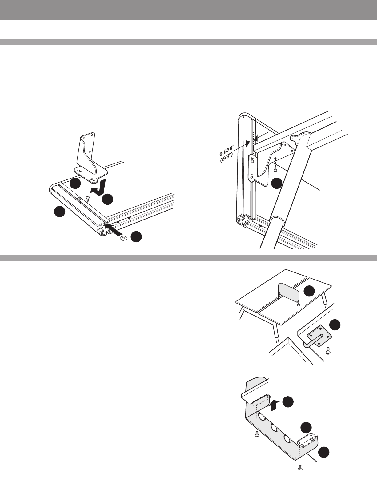
This divider secures to the rear edge of a table and serves as a privacy/modesty panel.
• Spring 2011
GENERAL INFORMATION
STEP 3: Engage key holes in the mounting bracket with the screws and tighten.
Pre-assemble the divider and mounting brackets:
STEP 1: Lay the divider on a clear surface.
STEP 2: Slide two rectangular anchor nuts through the bottom of the groove in the
divider’s vertical frame member. Align the nuts with two holes in the bottom of the
groove (this determines constant height of all brackets) and partially drive in two
screws.
NOTE: The screws are actually longer than the depth of the groove. The rectangular
anchor nuts must be positioned exactly above the holes in divider’s vertical, to allow
the longer screws to locate in the hole.
3
2
1
2
STEP 4: Have two people hold the divider bracket against bottom of the table worksurface while a third person secures the brackets with screws.
NOTE: Measure to leave 0.630”(5/8”) gap between divider’s vertical frame and the
back of the worksurface.
Once installed, ensure that the divider is perfectly vertical. Check and adjust alignment
if there are more dividers installed.
4
Table Dividers
PERPENDICULAR TABLE DIVIDER
This divider secures to the rear table edge (between two back-to-back tables) and
serves to establish side-to-side territory. Front of the divider is equipped with a translucent suction cup to protect the worksurface it rests on.
Position the divider in desired location.
STEP 1: Let the front foot with the suction cup rest on worksurface,
while the rear bracket fits right under the rear edge of the worksurface.
STEP 2: Secure the rear bracket with supplied screws.
Once installed, ensure the divider is perfectly vertical.
PERSONAL BAY / PERSONAL BAY WITH INTEGRATED MODESTY PANEL
Place the Bay in desired location and press it against the rear table edge.
STEP 1: Slide both brackets up against the bottom of the worksurface.
STEP 2: Tighten acorn nuts.
STEP 3: Ensure that the side panels are perpendicular to the rear worksurface edge and
secure the Bay by driving supplied screws through the brackets into the worksurface.
1
2
1
2
3
•Pageglobalcontract.com 12
Page 14
GLOBALContract
INSTALLATION GUIDELINES
Modesty Panel
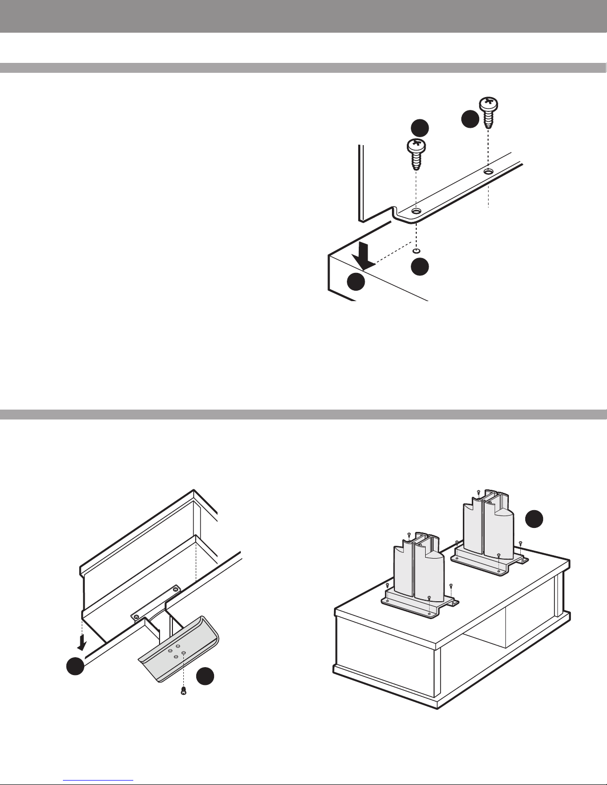
This modesty panel secures to the bottom of table worksurface.
Place table upside down on a clean surface.
• Spring 2011
STEP 1: Place the Modesty Panel on the reverse surface, with short lip pointing
towards the centre of the table.
STEP 2: Align the first and the last hole in the Modesty Panel lip with two holes predrilled in the worksurface.
STEP 3: Secure the Modesty Panel by driving supplied screws into the first and the
last hole.
STEP 4: Complete the installation by securing the remainder of the Modesty Panel
with supplied wood screws.
3
4
2
1
Bridges Box
Ensure that back-to-back table installation is complete, level and structurally
sound.
STEP 1: Place the Bridges Box upside down on a clean surface, align supporting brackets with pre-drilled holes and secure both with supplied wood screws.
2
3
STEP 2: Position the Box in the desired location, over the gap between two
back-to-back tables.
STEP 3: Align holes in the bottom plate with holes in the upright brackets and
secure with supplied machine screws.
1
Page • globalcontract.com13
 Loading...