

Page 1

Licence 2
Installation
Manual
2017
ISO 9001:2015OHSAS 18001:2007 ISO 14001:2015
REVISED: FALL 2017
Visit us on the Internet at globalcontract.com • (416) 739-5000
Global Contract Inc. 565 Petrolia Road
North York, Ontario, M3J 2X8
Page 2

GLOBALContract
INSTALLATION GUIDELINES
• Fall 2017
Table Of Contents
Assembly Hardware
Pre-Drilling Sheet
Product Installation
L2DRxxxxFB
L2DR-FB
L2DR-BL
L2DRHxxxxBR
L2ERxxxxFL
L2ERH-FL
L2GRxx
L2GB
L2GBxxL
L2GD
L2GDP
L2CRSxxxx
L2CRSHxxxx
L2RCxxxxL
L2RCHxxxxL
L2RCxxxxC
L2RCHxxxxC
L2ER R / L2ER L
L2ERH-L
L2Bxxxx
L2ECxxxxxxR
L2CC
L2CCxxxxxx
L2CK
L2CHK
L2TDHxxxxxx
L2TDxxxxxx
L2TCDxxxxxx
L2FDxxxxxx
P.01
04
P.05
06
08
10
12
14
16
18
20
22
24
26
28
30
32
34
36
38
40
42
44
46
48
50
52
54
56
58
60
61
L2PBBFxx
L2HHxxHxx
L2B2Hxxxx
L2BC2Hx02
Grommet Cut
Dimensions
Tackboards
89
90
92
94
P.96
P.97
Dimension Chart
Kadin Tables
Flip Top Tables
viceversa Tables
FreeFit
Please contact your Global Contract Service Representative at 416-739-5000 for
any questions or concerns.
NOTE: Any alterations to listed components will void the manufacturer’s warranty.
The manufacturer will not be responsible for any damage or bodily harm caused
by alterations in accordance with national or local electrical codes and manufac-
P.62
P.72
P.74
P.78
P.82
turer’s specifi cations. In accordance with the manufacturer’s policy of continual
product improvement, the product presented in this document is subject to
change without notice or obligation.
Page • globalcontract.com1
Page 3
GLOBALContract
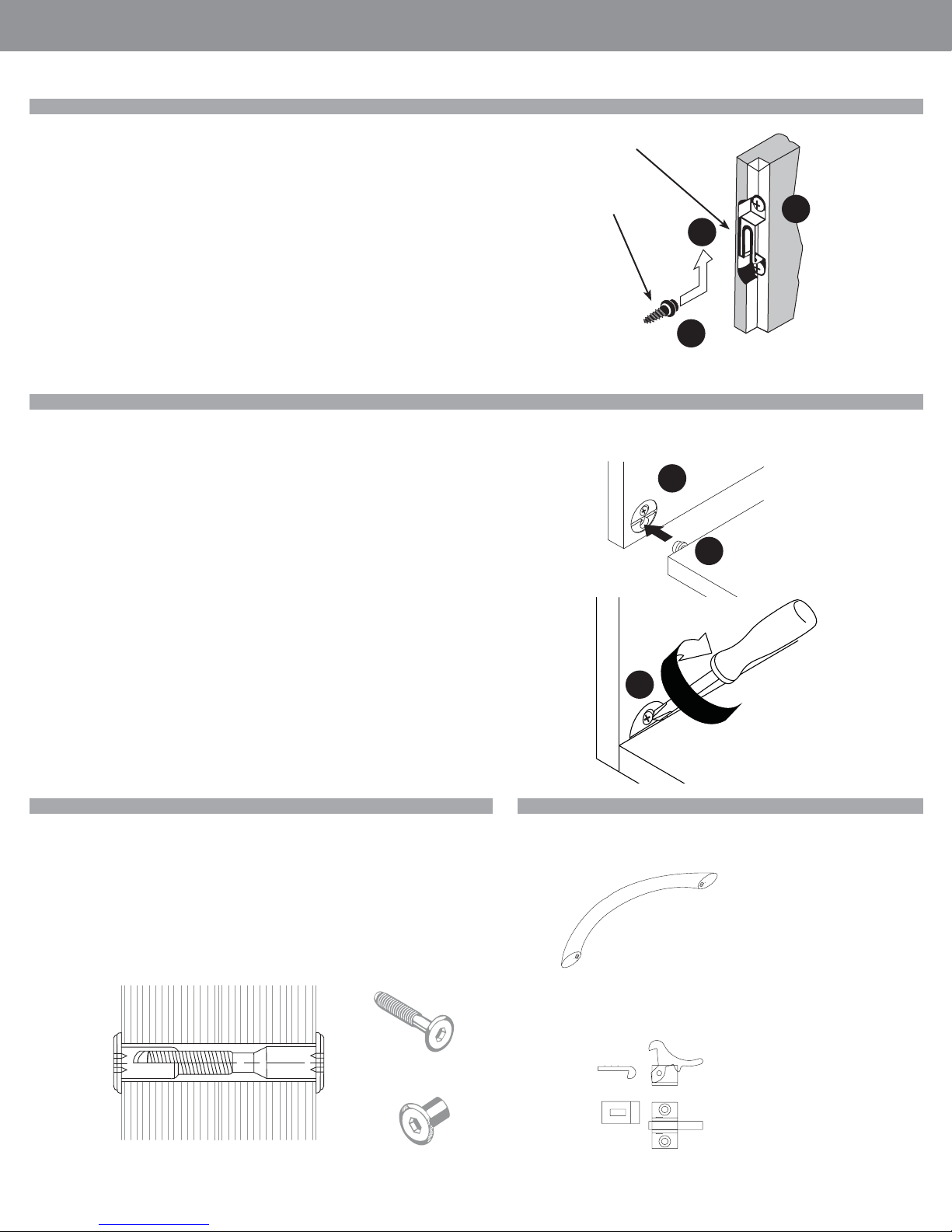
Assembly Hardware - Modular Connectors
Modular Connector (clip) and Shoulder Screw
• This connector offers a hidden connection between two panels.
• The modular connector and a connector screw are used in combination to
assemble panels.
• The modular connector is always pre-installed by the factory.
• The modular connector is always installed with the WIDE opening oriented at the
bottom of the part.
• The connecting shoulder screw is fi eld installed, based on the application of
components.
Steps to install modular connectors:
STEP 1: Install connecting shoulder screws at the pre-drilled location as per confi guration.
• Fall 2017
INSTALLATION GUIDELINES
Modular Connector (clip)
Shoulder Screw
3
1
STEP 2: Line up shoulder screws to the modular connector in another component.
STEP 3: Push components together and push down to lock component in place,
using a rubber mallet, if necessary.
Assembly Hardware - Blum Connectors
STEP 1: Install Blum Connector screws into the pre-drilled holes.
STEP 2: Line Blum connector screws to the exposed Blum Connectors
STEP 3: On the bottom of the surface turn the screw on Blum Connector ¼ turn, do
not over tighten.
2
1
2
3
Assembly Hardware - Joint Conncetor
This type of connector is used to attach the extrusion to the 1” end gables.
Steps to install connectors:
STEP 1: Press nut connector into pre-drilled hole of end gable from the exterior side
of the end gable.
STEP 2: Push bolt into extrusion holes.
STEP 3: Screw the nut and bolt together.
Assembly Hardware - Handels, Elbow Catch
Door / Drawer Handle
Install the handle(s) in the predrilled holes on the
doors or drawers by using the screws provided.
Elbow Catch
Install the elbow catch on the left hand door at
the upper right corner with the screws provided.
Joint Connector Bolt
Joint Connector Nut
•Pageglobalcontract.com 2
Page 4
GLOBALContract
INSTALLATION GUIDELINES
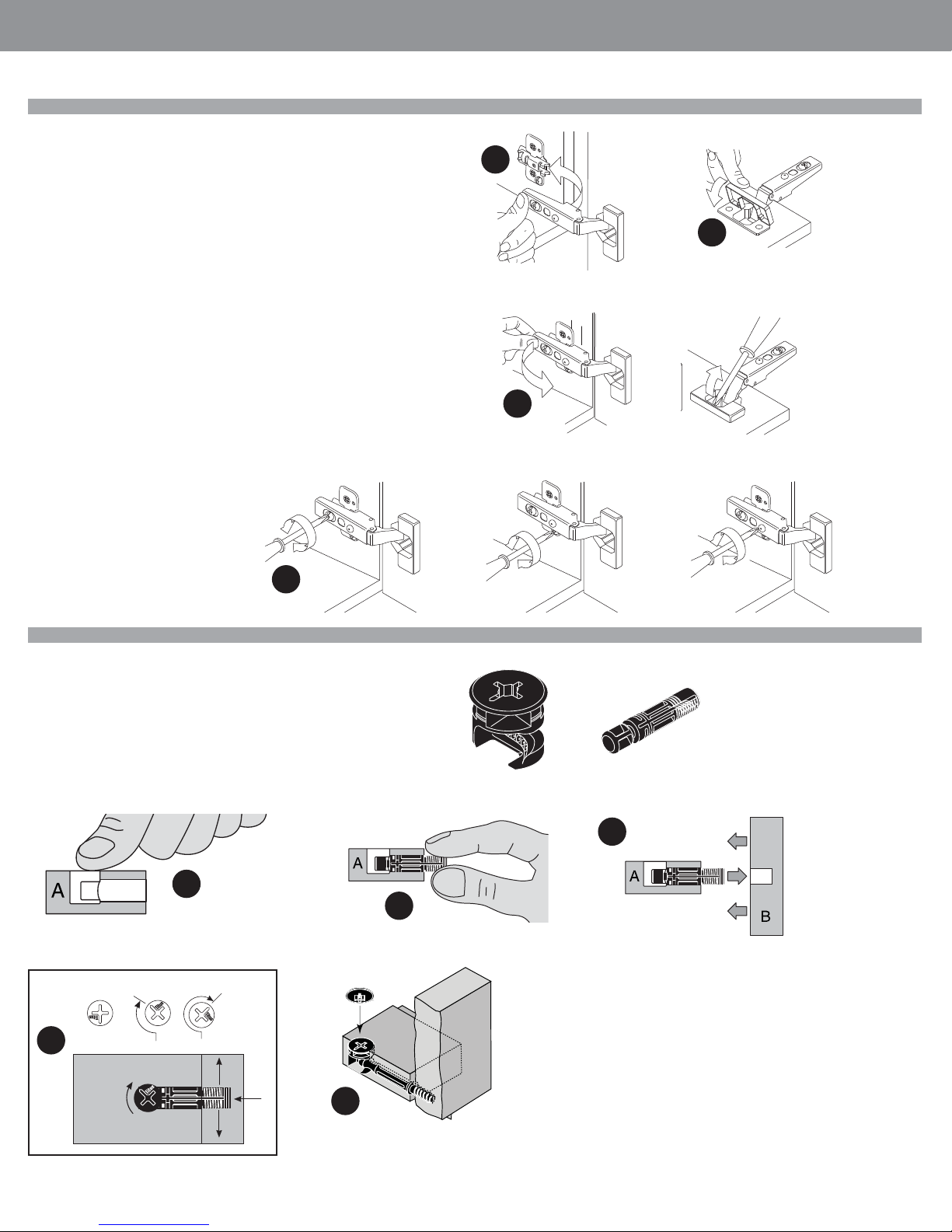
Assembly Hardware - Hinges
Hinge & Mounting Plate with Euro Screws
• The hinge is a tool-free attachment of hinge to door.
• Individual components and fi ttings do not need to be assembled until they reach
their fi nal destination.
• The mounting plate with Euro screws is easy to install.
• The spring loaded clip makes a simple connection between the door and the end
panel or divider.
Steps to install hinges:
STEP 1: Install all mounting plates using the predrilled holes of end panel and/or
dividers by fastening with the Euro screws.
Note: The mounting plate should be oriented with the arrow pointing towards
exterior of the unit.
STEP 2: Place the door face down. With the lever open press hinge into the predrilled holes. Press the lever on the hinge down with your thumb. By closing the
lever, the hinge is held fi rmly in place.
Assembly
Removal
• Fall 2017
1
2
STEP 3: Align hinges to mounting plates and push in until a click is heard.
STEP 4: Use adjusting screws on the hinge to level the door.
3
Height AdjustmentDepth Adjustment Side Adjustment
4
Assembly Hardware For Storage Components - Titus Connectors
STEP 1: Press the cam into the faceboard.
STEP 2: Insert the dowel into the side panel.
STEP 3: Assemble the panels.
STEP 4: Tighten the cam to lock the dowel.
STEP 5: Assemble the panels.
Universal Cam Quickfi t - TL Dowel
3
1
START MIN MAX
4
LOCK
Page • globalcontract.com3
2
5
Page 5
GLOBALContract
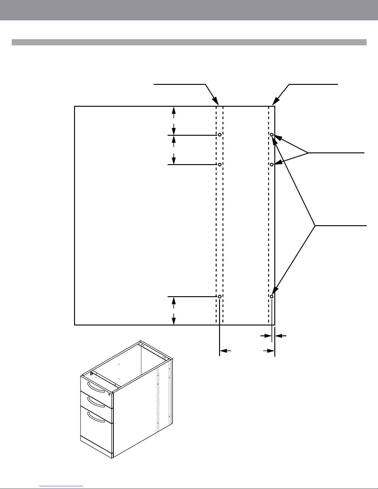
Pre-Drilling Location Sheet L2
Template for predrilling the hole location on the pedestals for use with modesty panels.
L2ER - BL/BR
L2DR - BL/BR
L2DR - FB/BF
92.2mm
96mm
• Fall 2017
INSTALLATION GUIDELINES
FLUSH MOD6” REC MOD
HALF HEIGHT
MODESTY
102.7mm
FULL HEIGHT
MODESTY
9.5mm
162mm
•Pageglobalcontract.com 4
Page 6

GLOBALContract
INSTALLATION GUIDELINES
• Fall 2017
Page • globalcontract.com5
Page 7
GLOBALContract
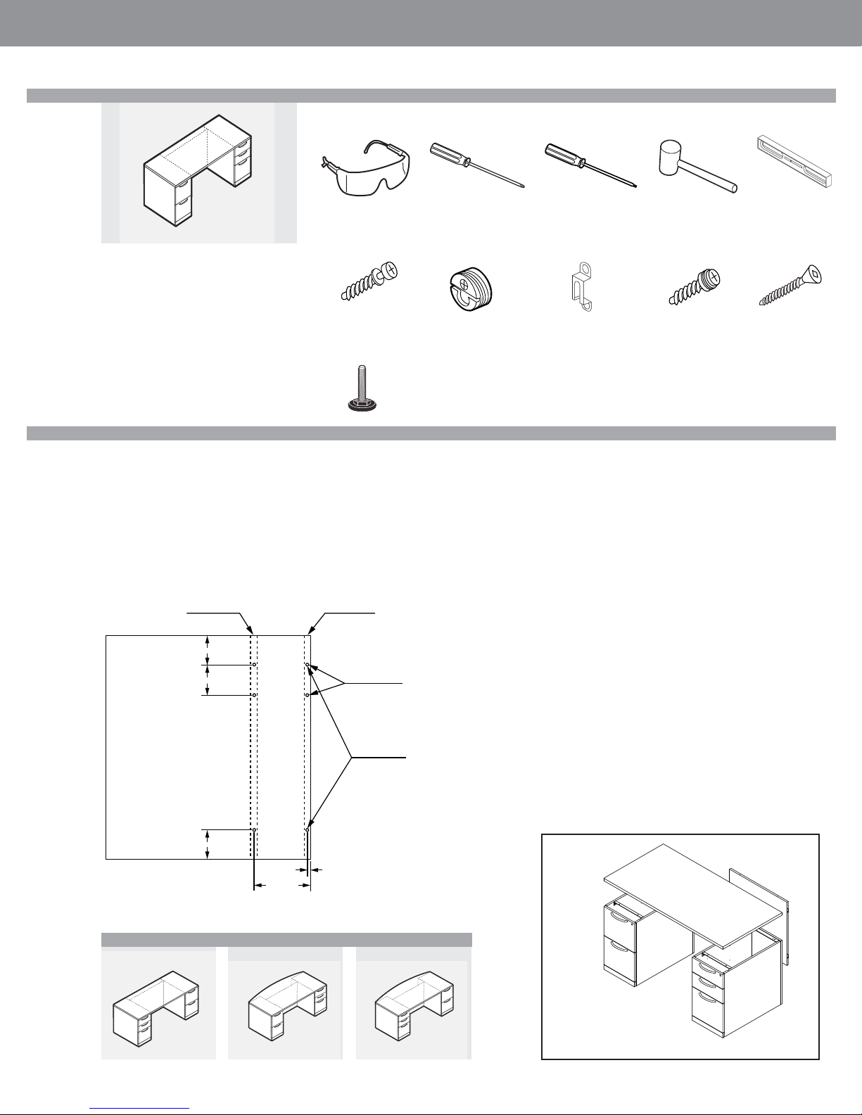
L2DRxxxxFB
NOTE: Open and assemble only one product
at a time to avoid a potential mix-up of parts
and hardware.
It is adviseable to assemble the unit on a
carpet to avoid scratches.
Required Tools
Safety Glasses
Included Hardware
Blum Connector
Screw L005650060
Leveler
L007250037
• Fall 2017
INSTALLATION GUIDELINES
Screwdriver #2 Phillips Rubber Mallet
Blum Connector
(installed) L005650061
Modular Connector
(installed) L004250001
Modular Screw
L007250001
LevelScrewdriver Roberson
Wood Screw #8 3/4
L007250032
Assembly
STEP 1: Unpack and inspect individual pieces for damages or missing hardware
STEP 2: Pick a clean unobstructed area to assemble desk. It is advisable to
assemble of this product upright.
STEP 3: Handles for pedestals are shipped installed on the inside of the cabinet.
Remove handle from the inside of the cabinet and re-install with the same screws
on the front of cabinet.
a. Levellers for pedestals are shipped inside the unit. These levellers should
be installed prior assembling complete unit.
FLUSH MOD6” REC MOD
92.2mm
HALF HEIGHT
96mm
102.7mm
9.5mm
162mm
MODESTY
FULL HEIGHT
MODESTY
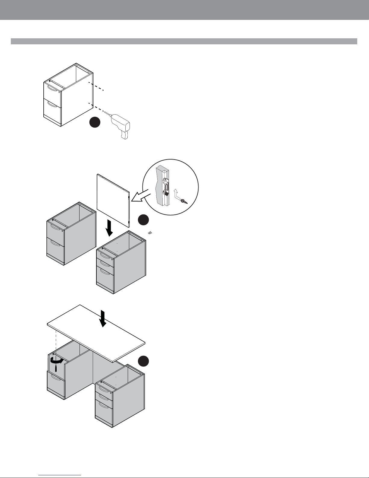
STEP 4: Arrange Pedestals as per the fi nal confi guration of the product.
a. Using a 1/8” drill bit, drill though holes into side of pedestal according to
the provided template on the side of the pedestal exposed to the underside
of the desk. For this application, use the half modesty and recessed panel location.
b. Modular screws are to be installed into these holes.
STEP 5: The modesty panel comes with Modular connectors installed on each
end of the panel.
On the top edge of the modesty panel, install Blum Connector screws into the
pre-drilled holes.
a. Attach the modesty panel to the pedestals by lining up modular con
nectors to screws installed on the pedestals, lift modesty and slide into
position ensuring to engage connectors to screws. You can use a mallet
to securely seat the modesty panel into position. Do this on both sides
STEP 6: To install the worksurface top.
The worksurface comes with Blum Connectors pre-installed on the bottom of
the surface. Lift worksurface over the assembly and line up Blum connectors to
the installed Blum connector screws on the back of the modesty panel. Turn the
screw on Blum Connector ¼ turn, do not over tighten.
a. You must also secure the worksurface top to the pedestals. Line up
the top fl ush to the side and front of the pedestals. Use #8 x 3/4 wood
screws provided, screw through the mounting bar on the pedestal to
secure the top. Note: Drawers need to be removed to access drilling location.
STEP 7: When fi nal position has been located, level the unit with the levellers
installed on both pedestals.
FULL MODESTY
WORKSURFACE
Installation For Similar Products
L2DRxxxxBF L2DBxxxxFB L2DBxxxxBF
FF PED
BBF PED
•Pageglobalcontract.com 6
Page 8
GLOBALContract
INSTALLATION GUIDELINES
4
• Fall 2017
5
6
Page • globalcontract.com7
Page 9
GLOBALContract
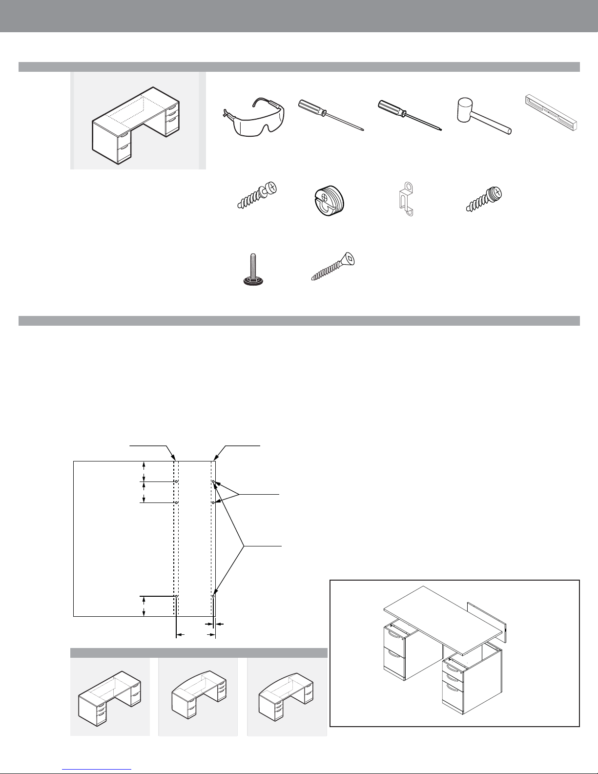
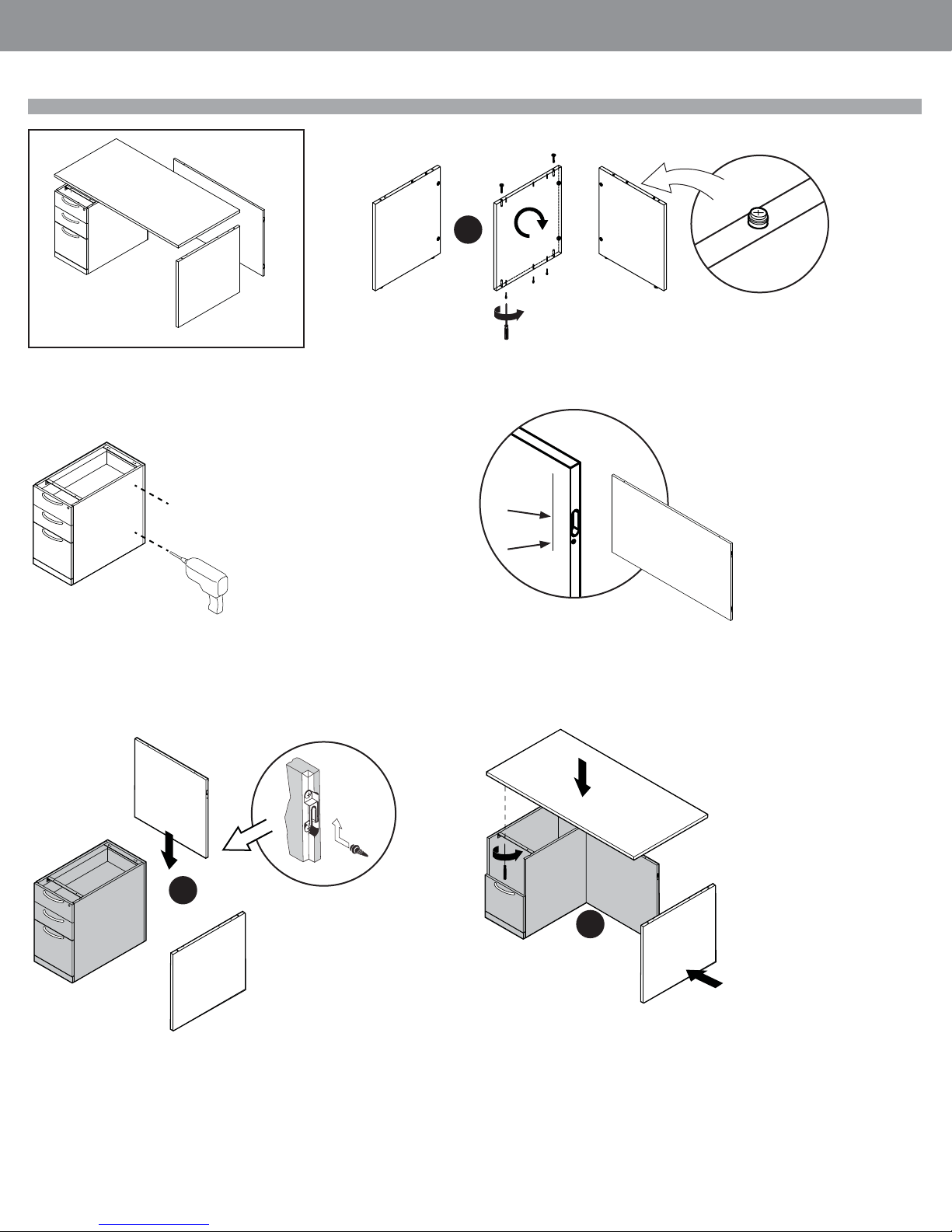
L2DR-FB Double Pedestal Desk
NOTE: Open and assemble only one product
at a time to avoid a potential mix-up of parts
and hardware.
It is adviseable to assemble the unit on a
carpet to avoid scratches.
Required Tools
Safety Glasses
Included Hardware
Blum Connector
Screw L005650060
Leveler
L007250037
• Fall 2017
INSTALLATION GUIDELINES
Screwdriver #2 Phillips Rubber Mallet
Blum Connector
(installed) L005650061
Wood Screw #8 3/4
L007250032
Modular Connector
(installed) L004250001
Modular Screw
L007250001
LevelScrewdriver Roberson
Assembly
STEP 1: Unpack and inspect individual pieces for damages or missing hardware
STEP 2: Pick a clean unobstructed area to assemble desk. It is advisable to assembly of this product upright.
STEP 3: Handles for pedestals are shipped installed on the inside of the cabinet.
Remove handle from the inside of the cabinet and re-install with the same screws
on the front of cabinet.
a. Levellers for pedestals are shipped inside the unit. These levellers should
be installed prior assembling complete unit.
FLUSH MOD6” REC MOD
92.2mm
HALF HEIGHT
96mm
102.7mm
9.5mm
162mm
MODESTY
FULL HEIGHT
MODESTY
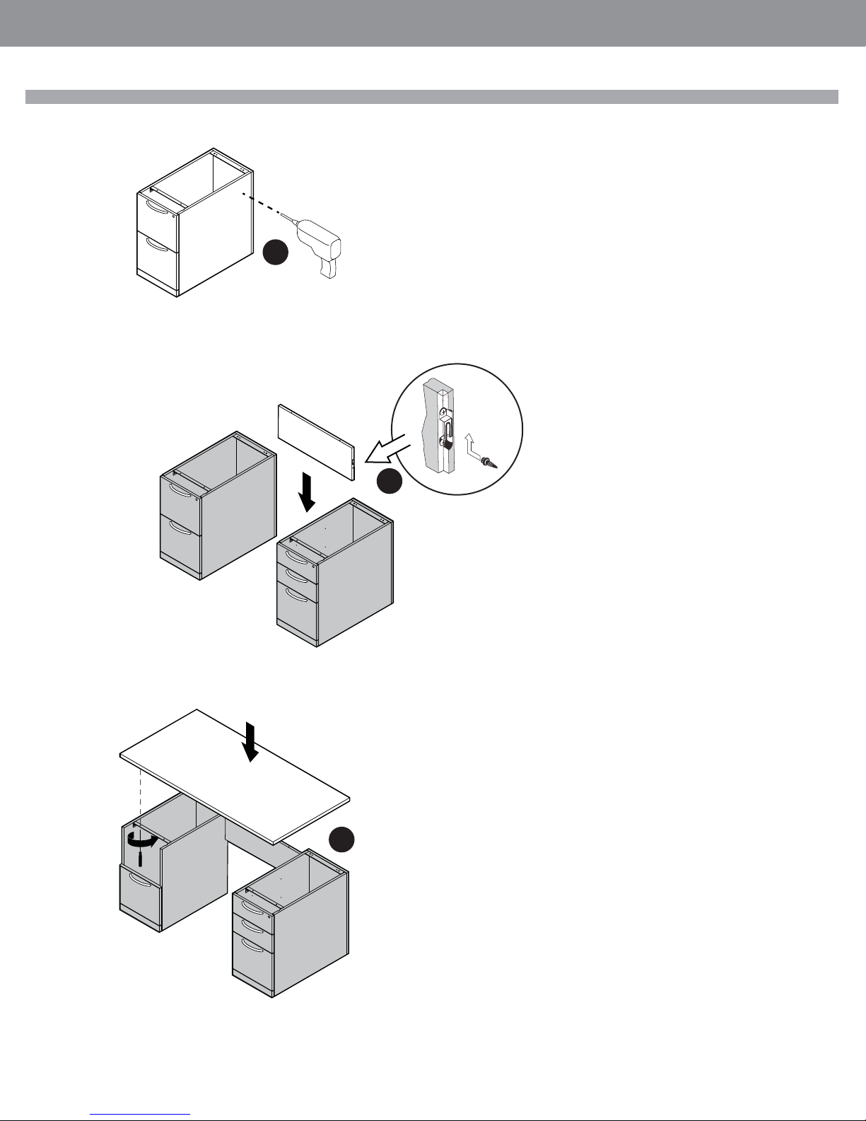
STEP 4: Arrange Pedestals as per the fi nal confi guration of the product
a. Using a 1/8” drill bit, drill though holes into side of pedestal according to
the provided template on the side of the pedestal exposed to the underside
of the desk. For this application, use the half modesty and recessed panel location
b. Modular screws are to be installed into these holes
STEP 5: The modesty panel comes with Modular connectors installed on each end
of the panel. On the top edge of the modesty panel, install Blum Connector screws
into the pre-drilled holes.
a. Attach the modesty panel to the pedestals by lining up modular con
nectors to screws installed on the pedestals, lift modesty and slide into
position ensuring to engage connectors to screws. You can use a mallet to
securely seat the modesty panel into position. Do this on both sides
STEP 6: To install the worksurface top. The worksurface comes with Blum Connectors pre-installed on the bottom of the surface. Lift worksurface over the assembly
and line up Blum connectors to the installed Blum connector screws on the back of
the modesty panel. Turn the screw on Blum Connector ¼ turn, do not over tighten.
a. You must also secure the worksurface top to the pedestals. Line up the
top fl ush to the side and front of the pedestals. Use #8 x 3/4 wood screws
provided, screw through the mounting bar on the pedestal to secure the
top. Note: Drawers need to be removed to access drilling location.
7. When fi nal position has been located, level the unit with the levellers installed on
both pedestals.
HALF MODESTY
WORKSURFACE
Installation For Similar Products
L2DRxxxxBF L2DBxxxxFB L2DBxxxxBF
FF PED
BBF PED
•Pageglobalcontract.com 8
Page 10
GLOBALContract
INSTALLATION GUIDELINES
4
• Fall 2017
5
6
Page • globalcontract.com9
Page 11
GLOBALContract
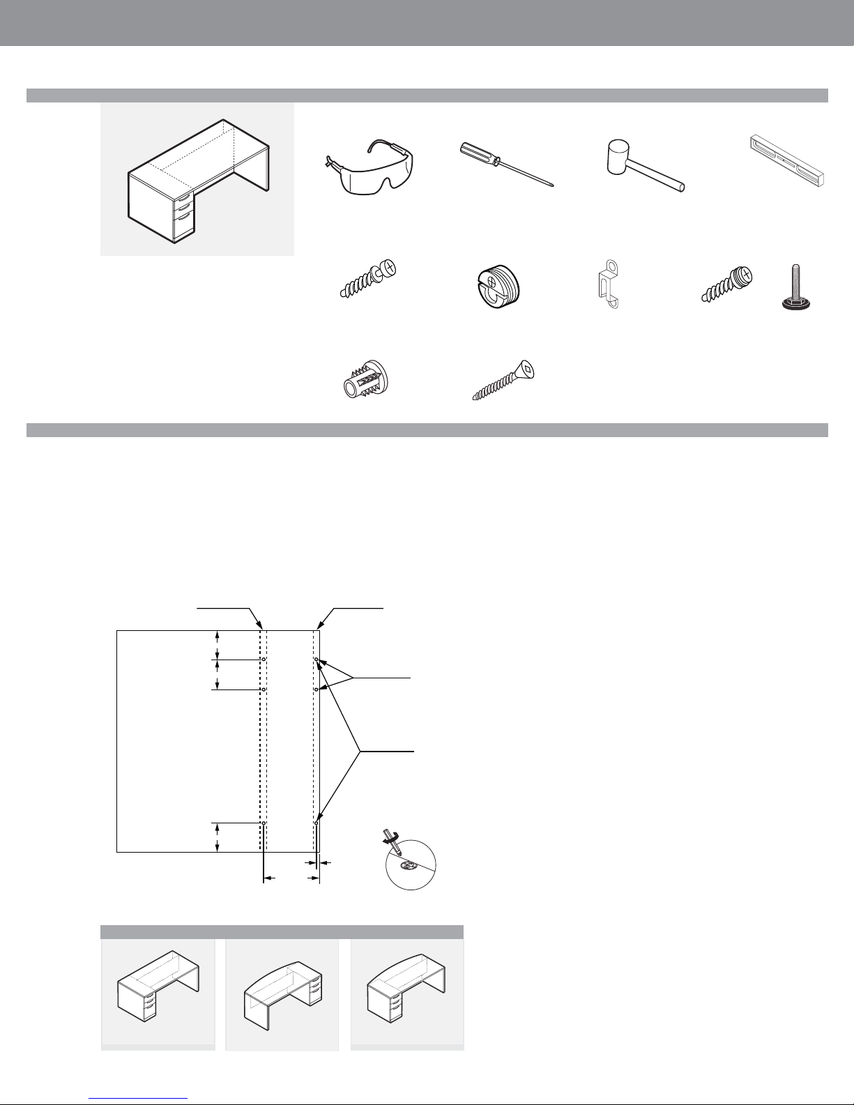
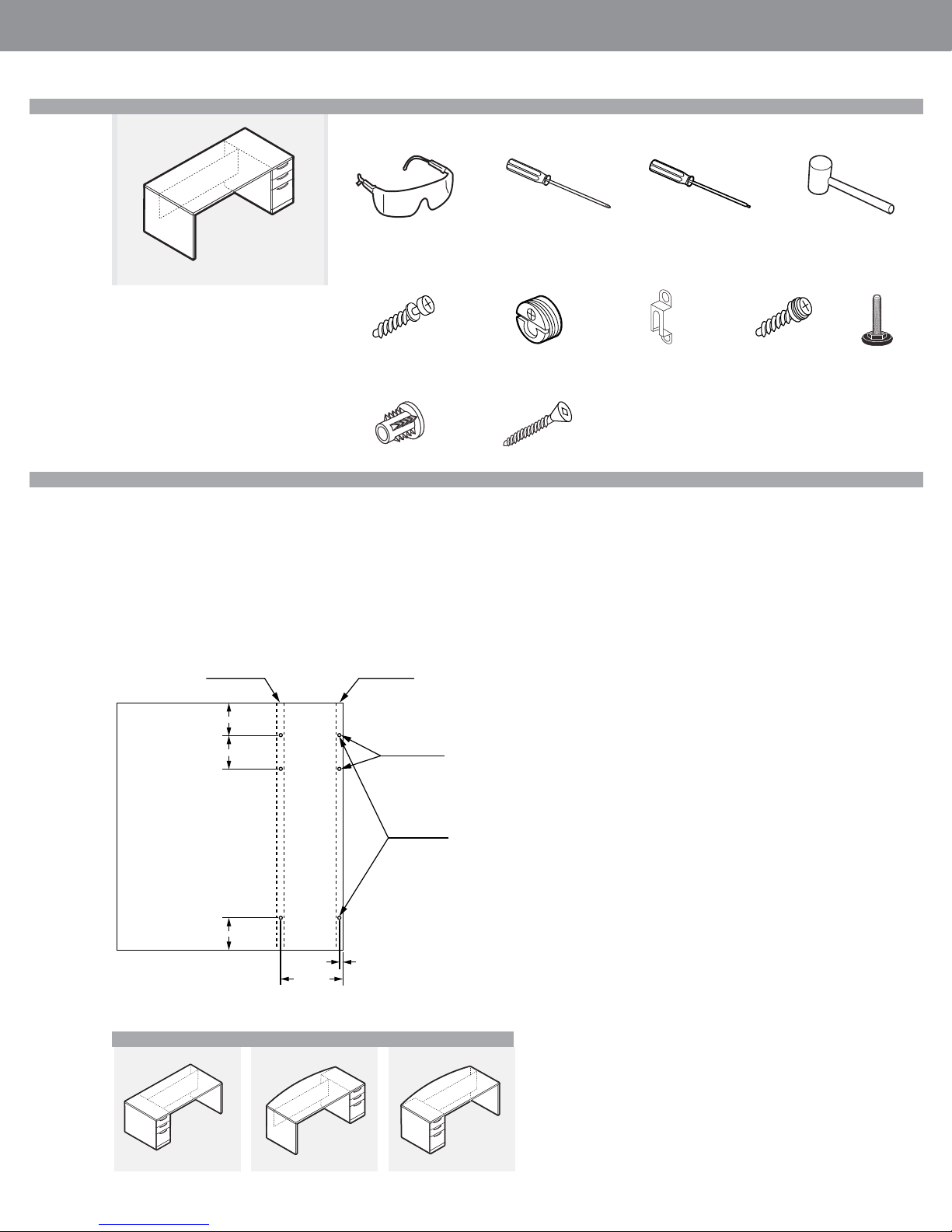
L2DR-BL Single Pedestal Desk
NOTE: Open and assemble only one product
at a time to avoid a potential mix-up of parts
and hardware.
It is adviseable to assemble the unit on a
carpet to avoid scratches.
INSTALLATION GUIDELINES
Required Tools
Safety Glasses Rubber Mallet
Included Hardware
Blum Connector
Screw L005650060
“T” Nut Insert
L007250039
Screwdriver #2 Phillips
Blum Connector
(installed) L005650061
Wood Screw #8 3/4
L007250032
Modular Connector
(installed) L004250001
Modular Screw
L007250001
• Fall 2017
Level
Leveler
L007250037
Assembly
STEP 1:Unpack and inspect individual pieces for damages or missing hardware.
STEP 2: Pick a clean unobstructed area to assemble desk. It is advisable to assembly of this product upright.
STEP 3: Handles for Pedestals are Shipped Installed on the inside of the cabinet.
Remove handle from the inside of the cabinet and re-install with the same screws
on the front of cabinet.
a. Levellers for pedestals are shipped inside the unit. These levellers should
be installed prior assembling complete unit.
FLUSH MOD6” REC MOD
92.2mm
HALF HEIGHT
96mm
102.7mm
9.5mm
162mm
MODESTY
FULL HEIGHT
MODESTY
Back Panel
Top Underside
Installation For Similar Products
L2DRHxxxxBL L2DBHxxxxBR L2DBxxxxBL
STEP 4: IArrange Pedestal and gable as per the fi nal confi guration of the product.
a. Using a 1/8” drill bit, drill though holes into side of pedestal according to
the provided template on the side of the pedestal exposed to the underside
of the desk. For this application, use the full modesty and recessed panel
location.
b. Modular screws are to be installed into these holes
STEP 5: Gable has Blum connectors pre-installed. Orient gable with Blum Connectors facing inside of desk.
Install levelers into T nut inserts on the bottom of the Gable.
a. Install Blum Connector screws into pre-drilled holes on top edge of the gable
STEP 6: The modesty panel comes with Modular connectors installed on to connect to the Pedestal.
On the top edge of the modesty panel, install Blum Connector screws into the predrilled holes.
On side of Modesty panel lining up with the gable, install Blum Connector screws
into pre-drilled holes.
• There are 2 holes here, select hole closest to underside of assembly to
correctly line up with the Blum Connectors.
a. Attach the modesty panel to the pedestals by lining up modular con
nectors to screws installed on the pedestal, lift modesty and slide into
position ensuring to engage connectors to screws. You can use a mallet to
securely seat the modesty panel into position.
b. Connect the gable to the modesty panel by lining up Blum Connector
screws to the Blum connectors. Turn the screw on Blum Connector ¼ turn,
do not over tighten.
STEP 7: To install the worksurface top. The worksurface comes with Blum Connectors pre-installed on the bottom of the surface. Lift worksurface over the assembly
and line up Blum connectors to the installed Blum connector screws on the modesty panel and gable. Turn screw on Blum Connector ¼ turn, do not over tighten.
a. You must also secure the worksurface top to the pedestal. Line up the
top fl ush to the side and front of the pedestal. Use #8 x 3/4 wood screws
provided, screw through the mounting bar on the pedestal to secure the
top. Note: Drawers need to be removed to access drilling location.
STEP 8: When fi nal position has been located, level the unit with the levellers
installed on Gable and pedestal
•Pageglobalcontract.com 10
Page 12
GLOBALContract
INSTALLATION GUIDELINES
FULL MODESTY
WORKSURFACE
• Fall 2017
BBF PED
5
GABLE
LEFT HAND RIGHT HAND
Connection for pedestal
Connection for gable
6
Page • globalcontract.com11
7
Page 13
GLOBALContract
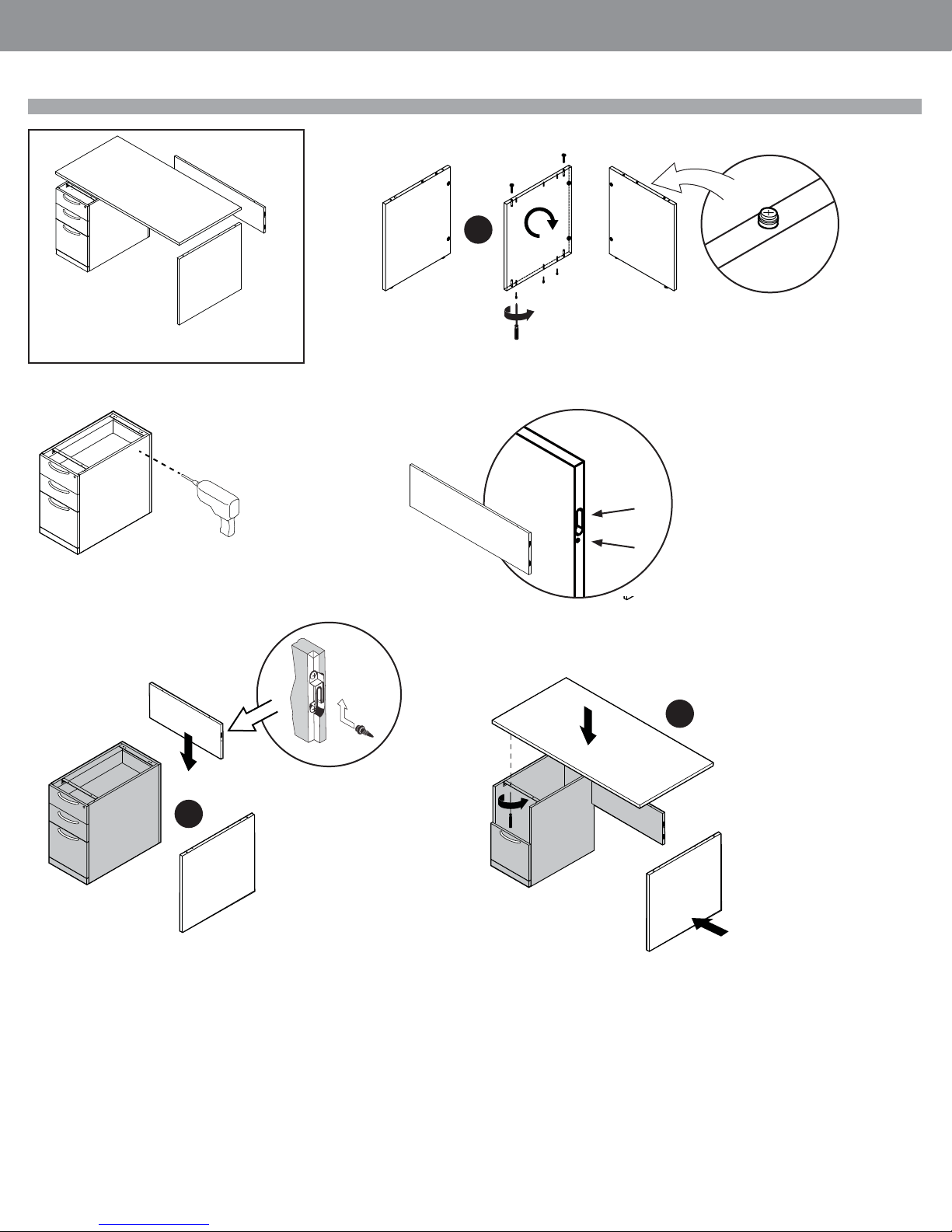
L2DRHxxxxBR • Single Pedestal Desk Resessed Half Modesty
NOTE: Open and assemble only one product
at a time to avoid a potential mix-up of parts
and hardware.
It is adviseable to assemble the unit on a
carpet to avoid scratches.
Required Tools
Safety Glasses
Included Hardware
Blum Connector
Screw L005650060
“T” Nut Insert
L007250039
• Fall 2017
INSTALLATION GUIDELINES
Screwdriver #2 Phillips
Blum Connector
(installed) L005650061
Wood Screw #8 3/4
L007250032
Screwdriver Roberson
Modular Connector
(installed) L004250001
Rubber Mallet
Modular Screw
L007250001
Leveler
L007250037
Assembly
STEP 1: Unpack and inspect individual pieces for damages or missing hardware
STEP 2: Pick a clean unobstructed area to assemble desk. It is advisable to assembly of this product upside down.
STEP 3: Handles for Pedestals are Shipped Installed on the inside of the cabinet.
Remove handle from the inside of the cabinet and re-install with the same screws
on the front of cabinet.
a. Levellers for pedestals are shipped inside the unit. These levellers should
be installed prior assembling complete unit.
FLUSH MOD6” REC MOD
92.2mm
HALF HEIGHT
96mm
102.7mm
9.5mm
162mm
MODESTY
FULL HEIGHT
MODESTY
Installation For Similar Products
L2DRHxxxxBL L2DBHxxxxBR L2DBxxxxBL
STEP 4: Arrange Pedestal and gable as per the fi nal confi guration of the product.
a. Using a 1/8” drill bit, drill though holes into side of pedestal according to
the provided template on the side of the pedestal exposed to the underside
of the desk. For this application, use the full modesty and recessed panel location.
b. Modular screws are to be installed into these holes
STEP 5: Gable has Blum connectors pre-installed. Orient gable with Blum Connectors facing inside of desk.
Install levellers into T nuts, using mallet install into pre-drilled holes on the bottom of gable.
a. Install Blum Connector screws into pre-drilled holes on top edge of the gable.
STEP 6: The modesty panel comes with Modular connectors installed on to
connect to the Pedestal. On the top edge of the modesty panel, install Blum Connector screws into the pre-drilled holes. On side of Modesty panel lining up with
the gable, install Blum Connector screws into pre-drilled holes.
• There are 2 holes here, select hole closest to underside of assembly to
correctly line up with the Blum Connectors.
a. Attach the modesty panel to the pedestals by lining up modular con
nectors to screws installed on the pedestal, lift modesty and slide into po
sition ensuring to engage connectors to screws. You can use a mallet to
securely seat the modesty panel into position.
b. Connect the gable to the modesty panel by lining up Blum Connector
screws to the Blum connectors. Turn the screw on Blum Connector ¼
turn, do not over tighten
STEP 7: To install the worksurface top. The worksurface comes with Blum
Connectors pre-installed on the bottom of the surface. Lift worksurface over the
assembly and line up Blum connectors to the installed Blum connector screws on
the modesty panel and gable. Turn screw on Blum Connector ¼ turn, do not over
tighten.
a. You must also secure the worksurface top to the pedestal. Line up the
top fl ush to the side and front of the pedestal. Use #8 x 3/4 wood screws
provided, screw through the mounting bar on the pedestal to secure the
top. Note: Drawers need to be removed to access drilling location
STEP 8: When fi nal position has been located, level the unit with the levellers
installed on Gable and pedestal.
•Pageglobalcontract.com 12
Page 14
GLOBALContract
INSTALLATION GUIDELINES
HALF MODESTY
TOP
• Fall 2017
BBF PED
5
GABLE
LEFT HAND RIGHT HAND
Connection for pedestal
Connection for gable
7
6
Page • globalcontract.com13
Page 15
GLOBALContract
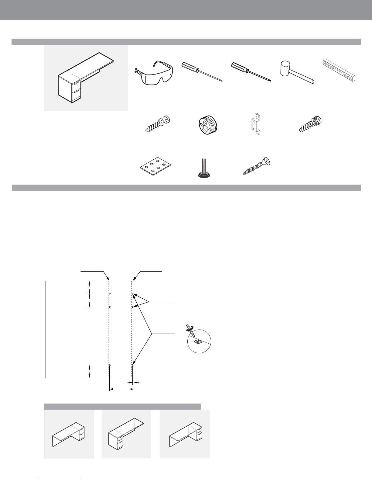
L2ERxxxxFL
NOTE: Open and assemble only one product
at a time to avoid a potential mix-up of parts
and hardware.
It is adviseable to assemble the unit on a
carpet to avoid scratches.
Required Tools
Safety Glasses
Included Hardware
Blum Connector
Screw L005650060
Flat Bracket
L005650025
• Fall 2017
INSTALLATION GUIDELINES
Screwdriver #2 Phillips Rubber MalletScrewdriver Roberson Level
Blum Connector
(installed) L005650061
Leveler
L007250037
Modular Connector
(installed) L004250001
Wood Screw #8 3/4
L007250032
Modular Screw
L007250001
Assembly
STEP 1: Unpack and inspect individual pieces for damages or missing hardware
STEP 2: Pick a clean unobstructed area to assemble desk. It is advisable to assembly of this product upright.
STEP 3: Handles for Pedestals are Shipped Installed on the inside of the cabinet.
Remove handle from the inside of the cabinet and re-install with the same screws
on the front of cabinet.
a. Levellers for pedestals are shipped inside the unit. These levellers should
be installed prior assembling complete unit.
FLUSH MOD6” REC MOD
92.2mm
HALF HEIGHT
96mm
102.7mm
MODESTY
FULL HEIGHT
MODESTY
Top Underside
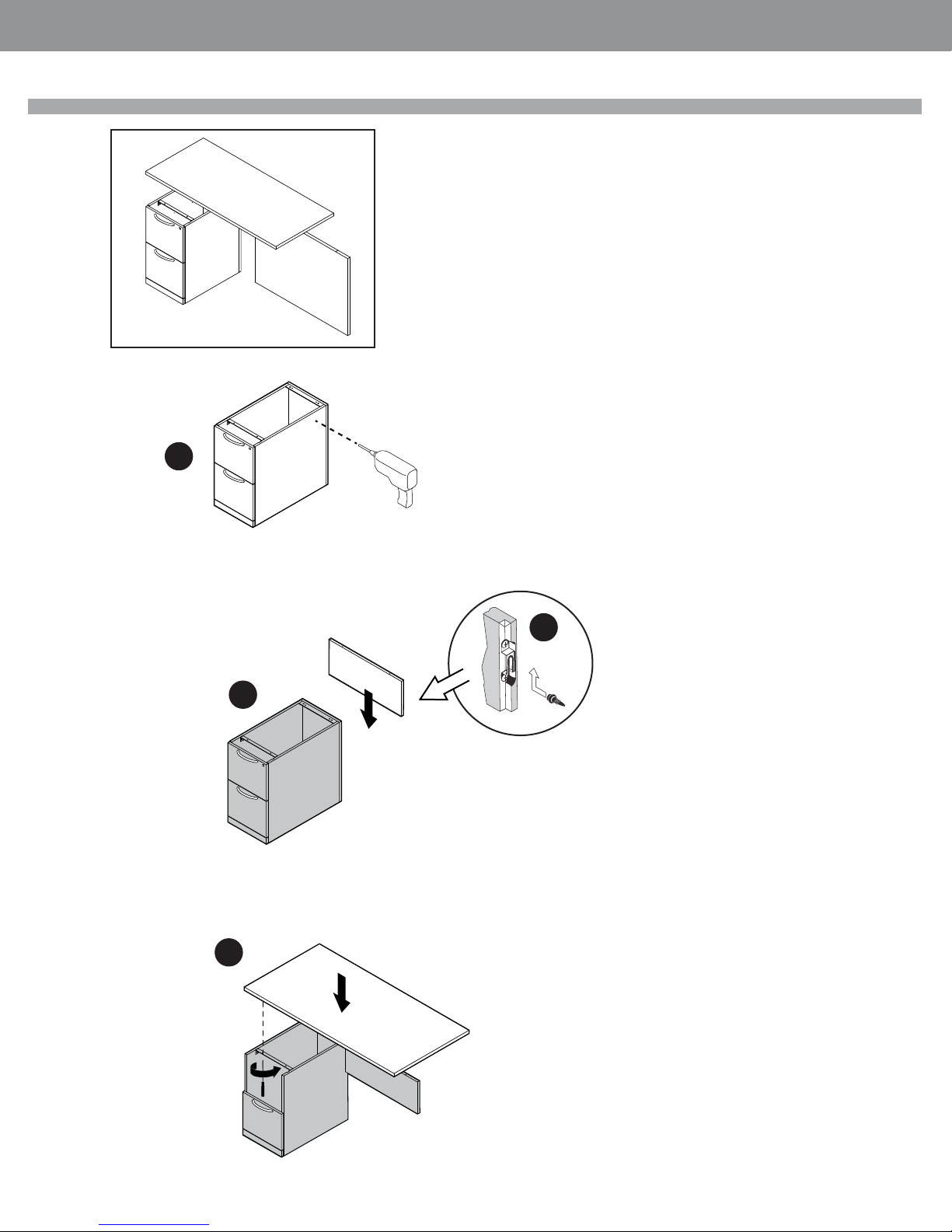
STEP 4: Arrange Pedestal and gable as per the fi nal confi guration of the product.
a. Using a 1/8” drill bit, drill though holes into side of pedestal according to
the provided template on the side of the pedestal exposed to the underside
of the desk. For this application, use the full modesty and fl ush panel location.
b. Modular screws are to be installed into these holes.
STEP 5: The modesty panel comes with Modular connectors installed to connect to
the Pedestal.
On the top edge of the modesty panel, install Blum Connector screws into the predrilled holes. There are 2 holes here, select hole closest to underside of assembly to
correctly line up with the Blum Connectors.
STEP 6: Attach the modesty panel to the pedestals by lining up modular connectors
to screws installed on the pedestal, lift modesty and slide into position ensuring to
engage connectors to screws. You can use a mallet to securely seat the modesty
panel into position.
STEP 7: To install the worksurface top. The worksurface comes with Blum Connectors pre-installed on the bottom of the surface. Lift worksurface over the assembly
and line up Blum connectors to the installed Blum connector screws on the modesty panel. Turn screw on Blum Connector ¼ turn, do not over tighten.
a. You must also secure the worksurface top to the pedestal. Line up the
top fl ush to the side and front of the pedestal. Use #8 x 3/4 wood screws
Back Panel
provided, screw through the mounting bar on the pedestal to secure the
top. Note: Drawers need to be removed to access drilling location.
8. This unit is intended to be attached to an adjoining assembled unit at the open
end using the provided Flat Brackets. The Flat Brackets are screwed into ganged
assemblies at the worksurface joint using #8 x ¾ wood screws.
9.5mm
162mm
Installation For Similar Products
L2DRxxxxFR L2ERxxxxBL L2ERxxxxBR
9. When fi nal position has been located, level the unit with the levellers installed on
the pedestal.
•Pageglobalcontract.com 14
Page 16
GLOBALContract
INSTALLATION GUIDELINES
WORKSURFACE
FF PED
FULL MODESTY
3
• Fall 2017
4
5
6
Page • globalcontract.com15
Page 17
GLOBALContract
L2ERH-FL
NOTE: Open and assemble only one product
at a time to avoid a potential mix-up of parts
and hardware.
It is adviseable to assemble the unit on a
carpet to avoid scratches.
Required Tools
Safety Glasses
Included Hardware
Blum Connector
Screw L005650060
Flat Bracket
L005650025
• Fall 2017
INSTALLATION GUIDELINES
Screwdriver #2 Phillips Rubber Mallet Level
Blum Connector
(installed) L005650061
Leveler
L007250037
Screwdriver Roberson
Modular Connector
(installed) L004250001
Wood Screw #8 3/4
L007250032
Modular Screw
L007250001
Assembly
STEP 1: Unpack and inspect individual pieces for damages or missing hardware
STEP 2: Pick a clean unobstructed area to assemble desk. It is advisable to assembly of this product upright.
STEP 3: Handles for Pedestals are Shipped Installed on the inside of the cabinet.
Remove handle from the inside of the cabinet and re-install with the same screws
on the front of cabinet.
a. Levellers for pedestals are shipped inside the unit. These levellers should
be installed prior assembling complete unit.
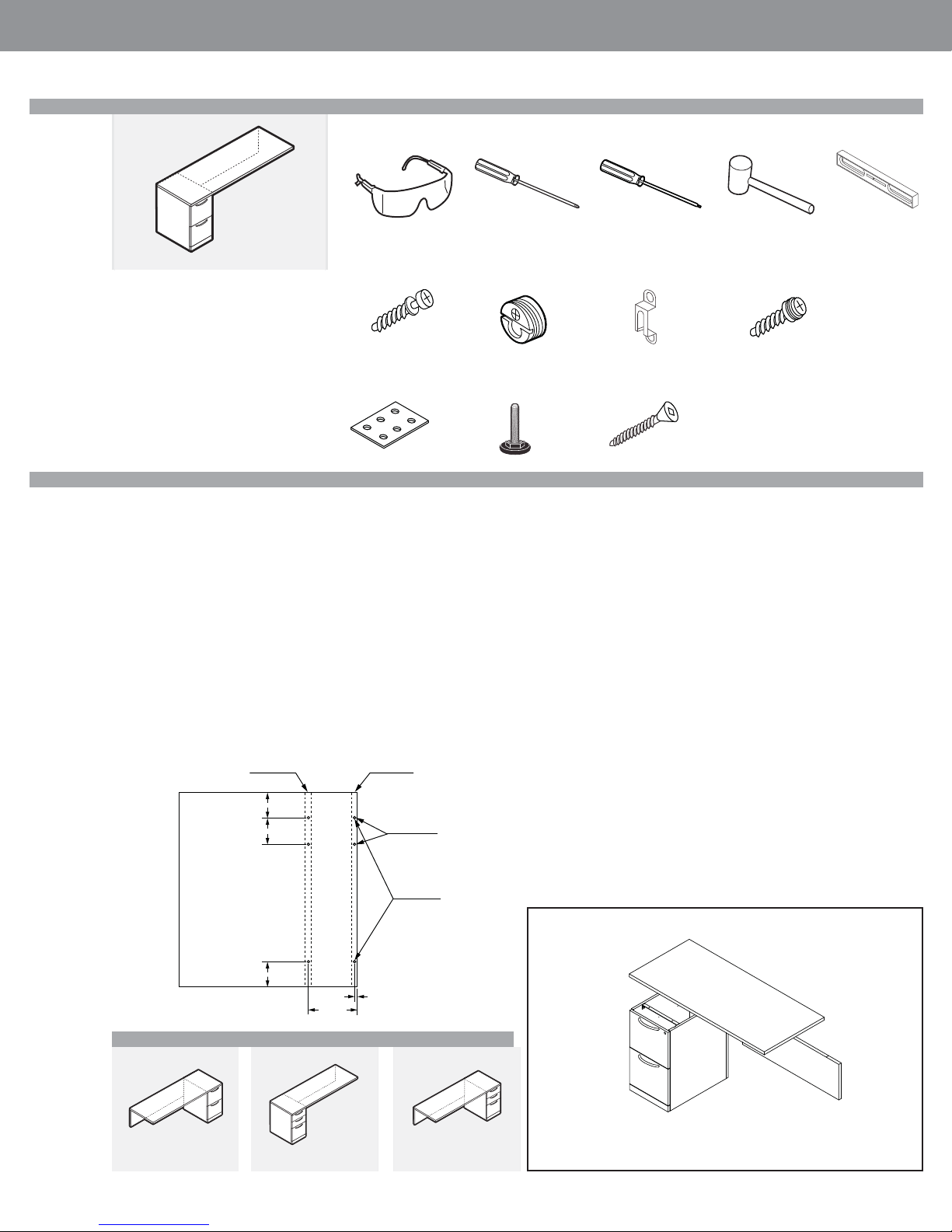
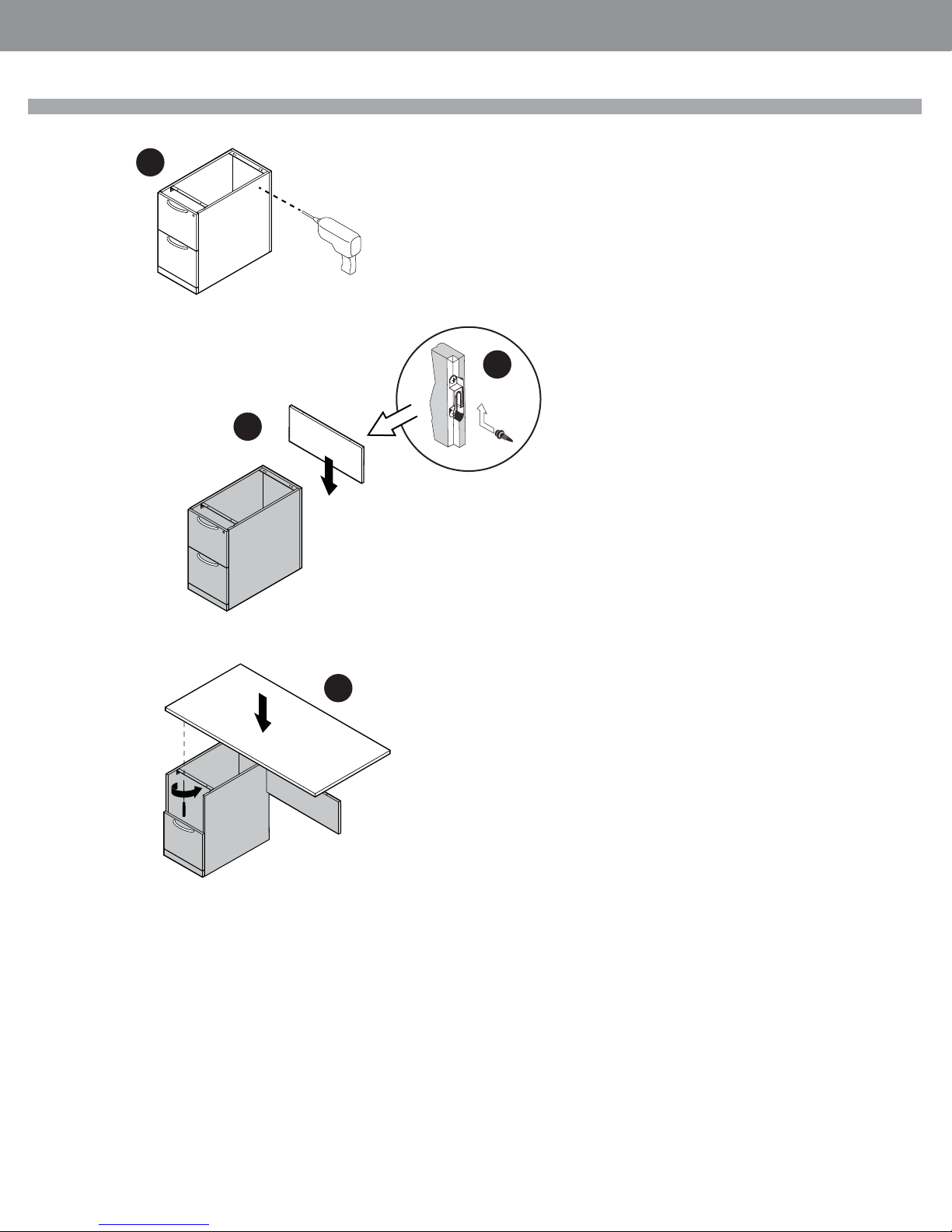
STEP 4: Arrange Pedestal and gable as per the fi nal confi guration of the product.
a. Using a 1/8” drill bit, drill though holes into side of pedestal according to
the provided template on the side of the pedestal exposed to the underside
of the desk. For this application, use the half modesty and fl ush panel location.
b. Modular screws are to be installed into these holes.
FLUSH MOD6” REC MOD
92.2mm
HALF HEIGHT
96mm
MODESTY
FULL HEIGHT
MODESTY
STEP 5: The modesty panel comes with Modular connectors installed to connect
to the Pedestal. On the top edge of the modesty panel, install Blum Connector
screws into the pre-drilled holes.
• There are 2 holes here, select hole closest to underside of assembly to
correctly line up with the Blum Connectors.
STEP 6: Attach the modesty panel to the pedestals by lining up modular connectors to screws installed on the pedestal, lift modesty and slide into position
ensuring to engage connectors to screws. You can use a mallet to securely seat
the modesty panel into position.
STEP 7: To install the worksurface top. The worksurface comes with Blum
Connectors pre-installed on the bottom of the surface. Lift worksurface over the
assembly and line up Blum connectors to the installed Blum connector screws on
the modesty panel. Turn screw on Blum Connector ¼ turn, do not over tighten
a. You must also secure the worksurface top to the pedestal. Line up the
top fl ush to the side and front of the pedestal. Use #8 x 3/4 wood screws
provided, screw through the mounting bar on the pedestal to secure the
top. Note: Drawers need to be removed to access drilling location.
STEP 8: This unit is intended to be attached to an adjoining assembled unit at the
open end using the provided Flat Brackets. The Flat Brackets are screwed into
ganged assemblies at the worksurface joint using #8 x ¾ wood screws.
STEP 9: When fi nal position has been located, level the unit with the levellers
installed on the pedestal.
102.7mm
Installation For Similar Products
L2ERHxxxxFR L2ERHxxxxBL L2ERxxxxBR
L2ERHxxxxBL
9.5mm
162mm
WORKSURFACE
FF PED
HALF MODESTY
•Pageglobalcontract.com 16
Page 18
GLOBALContract
INSTALLATION GUIDELINES
3
5
• Fall 2017
4
6
Page • globalcontract.com17
Page 19
GLOBALContract
L2GRxx
NOTE: Open and assemble only one product
at a time to avoid a potential mix-up of parts
and hardware.
Required Tools
Safety Glasses
Included Hardware
Blum Connector
Screw L005650060
• Fall 2017
INSTALLATION GUIDELINES
Screwdriver #2 Phillips Rubber MalletScrewdriver Roberson Level
Blum Connector
(installed) L005650061
Modular Connector
(installed) L004250001
Modular Screw
L007250001
It is adviseable to assemble the unit on a
carpet to avoid scratches.
Leveler
L007250037
“T” Nut Insert
L007250039
Assembly
STEP 1: Unpack and inspect individual pieces for damages or missing hardware
STEP 2: Pick a clean unobstructed area to assemble desk. It is advisable to assembly of this product upright.
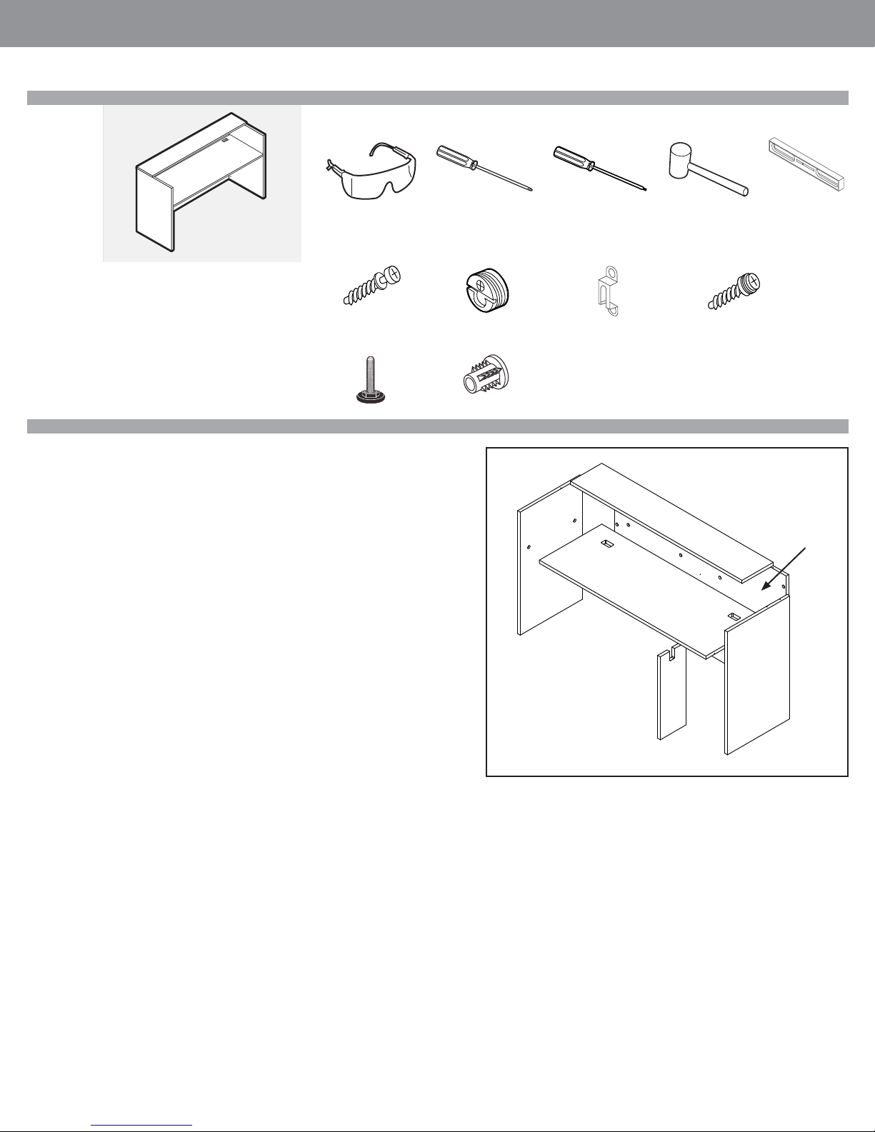
STEP 3: Install provided levellers into T nut inserts on the bottom of both left and
right hand end panels as well as half gable. Install T nuts, using mallet install into
pre-drilled holes on the bottom of gable. On the back and top edge of the end
panels, install Blum connector screws in pre-drilled holes.
STEP 4: On the worksurface, install Blum Connector screws in pre-drilled holes on
the back and side edges.
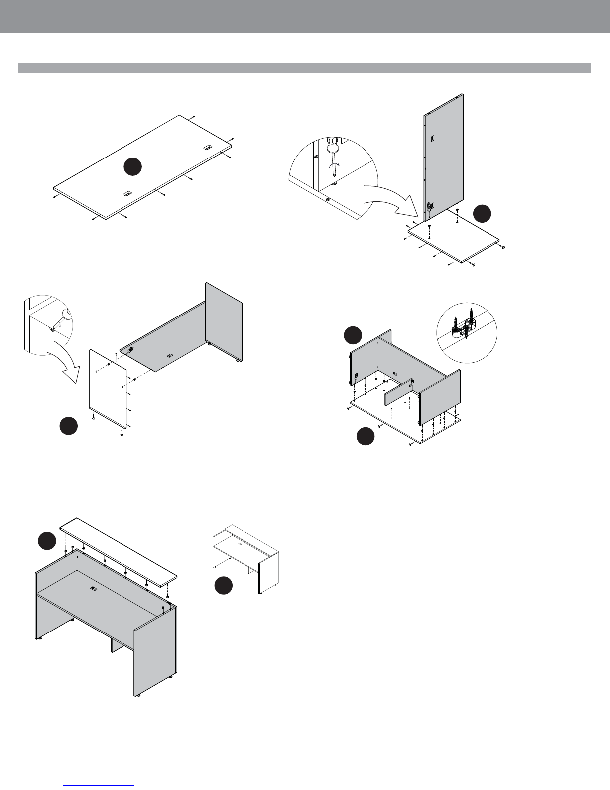
STEP 5: Lay the back panel on clean unobstructed surface with Blum Connectors
facing up. On the bottom edge, install the levellers into the T nut inserts. On the
top edge, install Blum connector screws into pre-drilled holes.
a. To attach the half gable mid support, install 2 modular connector screws in the
holes provide along center line. The half gable will connect to the back panel by
lining up modular connectors to the connector screws and slide down to engage. A
mallet may be used to properly seat the half gable.
TRANSACTION TOP
BACK PANEL
WORKSURFACE
HALF GABLE GABLE
STEP 6: lay either left or right end panel on the ground with exposed Blum connectors facing up. Connect the side of worksurface by lining up the Blum connector
screws to the Blum connectors. Tighten screws on Blum Connectors ¼ turn, do not
over tighten.
a. with the assistance of another person, turn assembly upright and connect opposite end panel by connecting Blum Connector screws.
STEP 7: Pick up assembly of the worksurface and end gables and line up Blum
Connector screws along the back end to the Blum connectors on the Back panel.
Tighten Blum Connector screws ¼ turn, Do not over tighten. Stand Assembly
upright.
STEP 8: To install transaction top, line the Blum Connectors installed on the bottom
of the top and line up with Blum connecting screws installed on the top edges of the
assembly. Tighten Blum Connector screws ¼ turn, Do not over tighten.
STEP 9: When in fi nal position, level the unit.
•Pageglobalcontract.com 18
Page 20
GLOBALContract
INSTALLATION GUIDELINES
4
• Fall 2017
6
7
6a
5
8
9
Page • globalcontract.com19
Page 21
GLOBALContract
L2GB
NOTE: Open and assemble only one product
at a time to avoid a potential mix-up of parts
and hardware.
It is adviseable to assemble the unit on a
carpet to avoid scratches.
Required Tools
Safety Glasses
#4 & 5 Hex Wrench
Included Hardware
Blum Connector
Screw L005650060
• Fall 2017
INSTALLATION GUIDELINES
Screwdriver #2 Phillips Rubber MalletScrewdriver Roberson Level
Blum Connector
(installed) L005650061
Flat Bracket
L005650025
Flat Bracket
L005651035
Wood Screw #8 3/4
L007250032
Connector Bolt
L005650114
Connector Nut
L005650117
Assembly
STEP 1: Unpack and inspect individual pieces for damages or missing hardware
STEP 2: Pick a clean unobstructed area to assemble desk. It is advisable to assembly of this product upright.
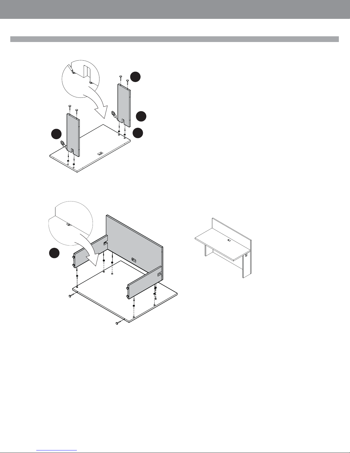
STEP 3: Install levellers into T nuts, using mallet install into pre-drilled holes on the
bottom of gable. Orient the gables as left and right with exposed drill holes on back
edge facing back.
Install Blum Connector screws into pre-drilled holes on back edge closest to underside of desk assembly.
a. install Blum Connector Screws on top edge of partial gables into pre drilled holes closest to underside of desk assembly.
STEP 4: On the worksurface, install Blum Connector screws in pre-drilled holes on
the back edge.
STEP 5: Lay worksurface bottom side up on clean unobstructed surface with Blum
Connectors facing up.
Install partial gables into Blum Connectors on the bottom of the surface. Insure
that the gables have Blum Connector screws facing underside of desk as confi gured
in step 3. Tighten Blum connectors ¼ turn, do not over tighten.
HALF GABLE
Leveler
L007250037
WORKSURFACE
“T” Nut Insert
L007250039
BACK PANEL
HALF GABLE
STEP 5: Lay the back panel on clean unobstructed surface with Blum Connectors
facing up. On the bottom edge, Install levellers into T nuts, using mallet install into
pre-drilled holes.
STEP 6: Pick up assembly of the worksurface and end gables and line up Blum
Connector screws along the back end to the Blum connectors on the Back panel.
Tighten Blum Connector screws ¼ turn, do not over tighten. Stand Assembly
upright.
STEP 7: This unit is intended to be attached to an adjoining assembled unit at both
ends using the provided Flat Brackets. The fl at brackets are screwed into ganged
assemblies at the worksurface joint using #8 x ¾ wood screws
half fl at bracket will be installed in “cableway” opening of partial gable.
a. Using Murikoshi Connector screw and ¼ - 2—2 Bolt, join half gables of
adjoin units though pre-drilled hole on the side of the gable.
•Pageglobalcontract.com 20
Page 22
GLOBALContract
INSTALLATION GUIDELINES
3
3a
• Fall 2017
5
6
4
Page • globalcontract.com21
Page 23
GLOBALContract
L2GBxxL
NOTE: Open and assemble only one product
at a time to avoid a potential mix-up of parts
and hardware.
It is adviseable to assemble the unit on a
carpet to avoid scratches.
Required Tools
Safety Glasses
#4 & 5 Hex Wrench
Included Hardware
Blum Connector
Screw L005650060
• Fall 2017
INSTALLATION GUIDELINES
Screwdriver #2 Phillips Rubber MalletScrewdriver Roberson Level
Blum Connector
(installed) L005650061
Flat Bracket
L005650025
Flat Bracket
L005651035
Wood Screw #8 3/4
L007250032
Connector Bolt
L005650114
Connector Nut
L005650117
Assembly
STEP 1: Unpack and inspect individual pieces for damages or missing hardware
STEP 2: Pick a clean unobstructed area to assemble desk. It is advisable to assembly of this product upright.
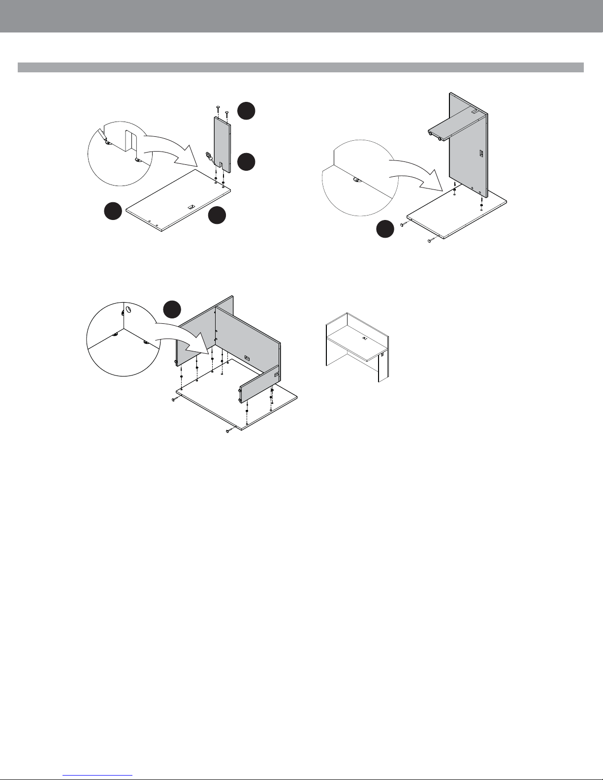
STEP 3. Install levellers into T nuts, using mallet install into pre-drilled holes on the
bottom of gable.
Orient the gables as left and right with exposed hole on back edge facing back, note
that the large end panel is handed.
a. Install Blum Connector screws into pre-drilled holes on back and top
edge of both the partial gable. Please note that the half gable is non
handed, there will be 2 holes for each Blum connector screw location.
Install screws in position closest to underside of assembled desk.
STEP 4: On the worksurface, install Blum Connector screws in pre-drilled holes on
the back edge and side matching the full height end panel.
STEP 5: Lay worksurface face down on Clean unobstructed surface with Blum
Connectors exposed.
Attach half gable to worksurface linming Blum Connectors screws with Blum Connectors. Tighten Blum Connector ¼ turn, do not over tighten.
a. Lay full end panel on clean unobstructed surface with exposed Blum
Connectors facing up. Connect worksurface to full end panel by lining up
Blum connecter screws to the Blum connectors on end panel. Tighten Blum
connectors ¼ turn, do not over tighten.
“T” Nut Insert
L007250039
STEP 6: Lay the back panel on clean unobstructed surface with Blum Connectors
facing up. On the bottom edge, install the levellers into the T nut inserts.
STEP 7: Pick up assembly of the worksurface and end gables and line up Blum
Connector screws along the back edge to the Blum connectors on the back panel.
Tighten Blum Connector screws ¼ turn, do not over tighten. Stand Assembly
upright.
STEP 8: This unit is intended to be attached to an adjoining assembled unit at open
side using the provided Flat Brackets. The Flat Brackets are screwed into ganged
assemblies at the worksurface joint using #8 x ¾ wood screws
Half fl at bracket will be installed in “cableway” opening of half gable.
a. Using Connector Bolt screw and Connector Nut, join half gables of
adjoin units though pre-drilled hole on the side of the gable.
STEP 9: When fi nal position has been located, level the unit with the levellers
installed on the pedestal.
END GABLE
WORKSURFACE
Leveler
L007250037
BACK PANEL
Installation For Similar Products
L2GRxxR
HALF GABLE
•Pageglobalcontract.com 22
Page 24
GLOBALContract
INSTALLATION GUIDELINES
3
3a
• Fall 2017
5
6
4
5a
3
Page • globalcontract.com23
Page 25
GLOBALContract
L2GD
NOTE: Open and assemble only one product
at a time to avoid a potential mix-up of parts
and hardware.
It is adviseable to assemble the unit on a
carpet to avoid scratches.
Required Tools
Safety Glasses
Included Hardware
Socket Screw
L005650180
Connector Bolt
L005650114
• Fall 2017
INSTALLATION GUIDELINES
Screwdriver #2 Phillips Rubber MalletScrewdriver Roberson #4 & 5 Hex Wrench
Spacer
L005650117
Connector Nut
L005650117
Connecting Dowel
L004250004
Connecting Cam
L002250002
Leveler
L007250037
Assembly
STEP 1: Unpack and inspect individual pieces for damages or missing hardware
STEP 2: Pick a clean unobstructed area to assemble desk.
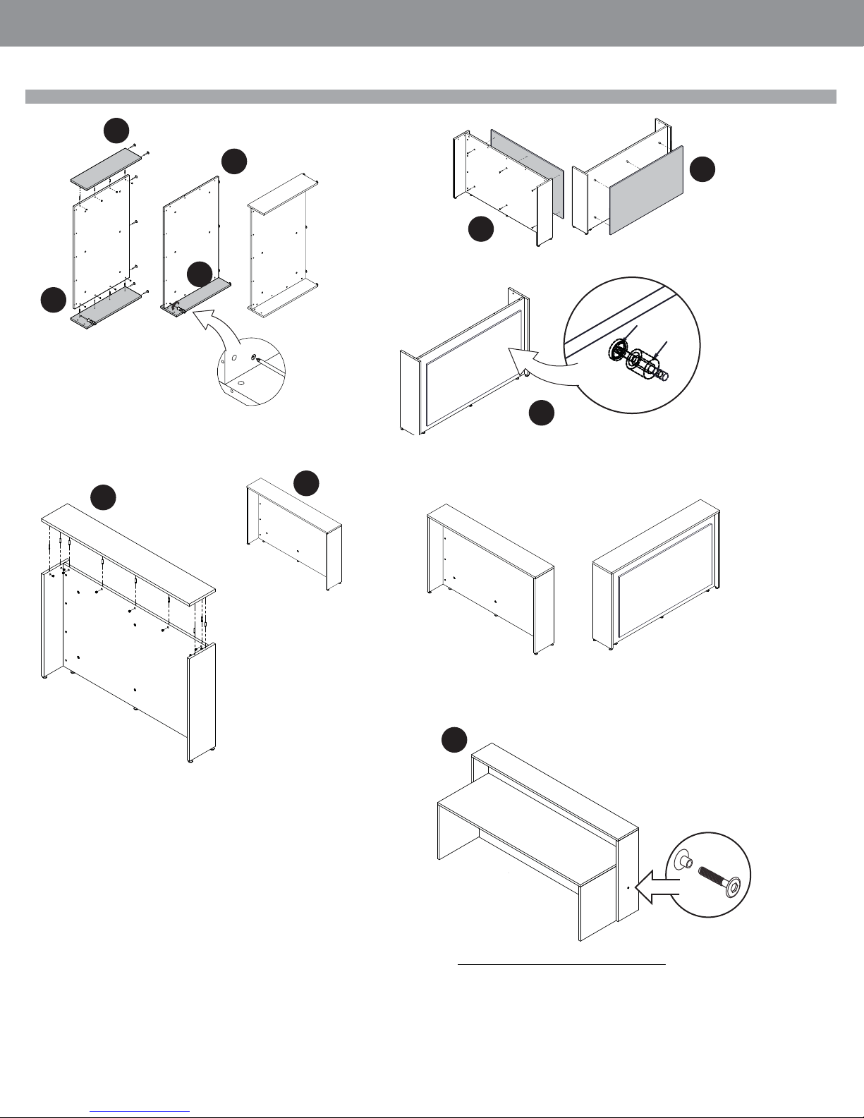
STEP 3 Orient left and right side panels, note that the holes for connectors face
underside of desk with the CONNECTING CAMS to the back.
a. install LEVELERS into T NUTS on the bottom of both side gables.
b. Install CONNECTING DOWELS in pre-drilled holes exposed near back edge.
STEP 4: Back panel, Install LEVELERS into T NUT inserts on the bottom of the
panel. Orient panel with holes for hardware to the underside of the desk.
STEP 5: Connect the side panels aligning the CONNECTING DOWELS with the
CONNECTING CAM. Turn cam to 2 o’clock position to secure. Do this to both sides.
Lay assembly down with outside facing up.
STEP 6: There are 6 exposed through holes with routered out “seats” for SPACERS.
Place each of the 6 SPACERS into these positions.
STEP 7: Pick up decorative panel, align installed nutserts on the back of this panel
with the spacers and place into position.
a. From under the assembly, insert the SOCKET SCREWS through exposed
holes and spacers into the T NUT inserts on the decorative panel, tighten
using hex wrench.
b. Stand assembly upright.
STEP 8: Insert the SOCKET SCEWS into the pre-drilled holes on the bottom of the
surface. Place top panel onto assembly aligning the CONNECTING DOWEL with the
CONNECTING CAMS. Turn cam to 2 o’clock position to secure.
STEP 9: This product is intended to be installed over a standard Licence shell.
Place into position and level both units together.
a. Drill a through hole using a 9.5mm bit though the side panel and gable
on the desk you attaching too. This hole should be centered front to back
and 12-15” from fl oor. Using the CONNECTOR BOLT & NUT, secure each
side and tighten with hex wrench.
•Pageglobalcontract.com 24
Page 26
GLOBALContract
SPACER
BOLT
INSTALLATION GUIDELINES
3a
• Fall 2017
3b
4
6
5
7a
7b
8
7
Page • globalcontract.com25
9
Page 27
GLOBALContract
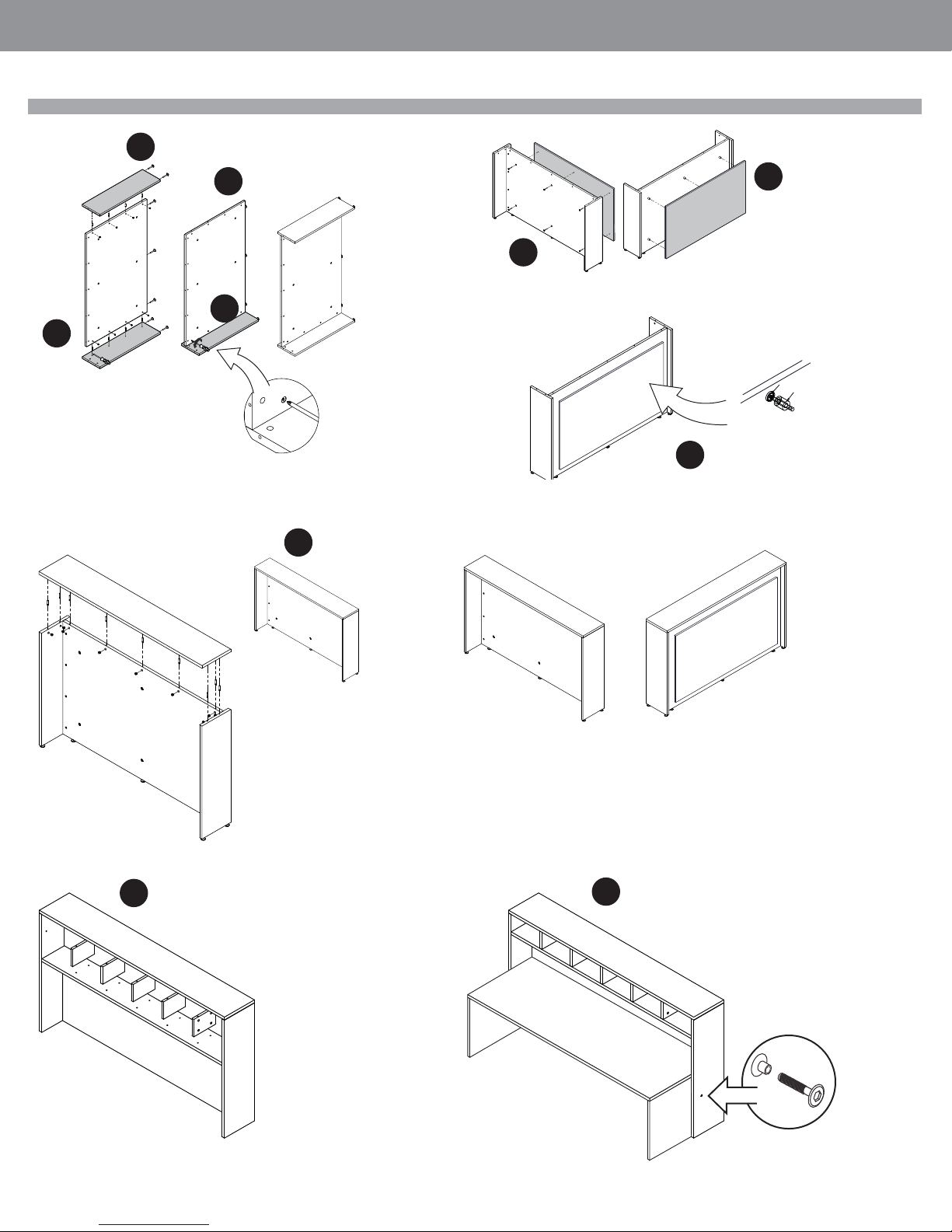
L2GDP
NOTE: Open and assemble only one product
at a time to avoid a potential mix-up of parts
and hardware.
It is adviseable to assemble the unit on a
carpet to avoid scratches.
Required Tools
Safety Glasses
Included Hardware
Socket Screw
L005650180
Connector Bolt
L005650114
• Fall 2017
INSTALLATION GUIDELINES
Screwdriver #2 Phillips Rubber MalletScrewdriver Roberson #4 & 5 Hex Wrench
Spacer
L005650117
Connector Nut
L005650117
Connecting Dowel
L004250004
Connecting Cam
L002250002
Leveler
L007250037
Assembly
STEP 1: Unpack and inspect individual pieces for damages or missing hardware
STEP 2: Pick a clean unobstructed area to assemble desk.
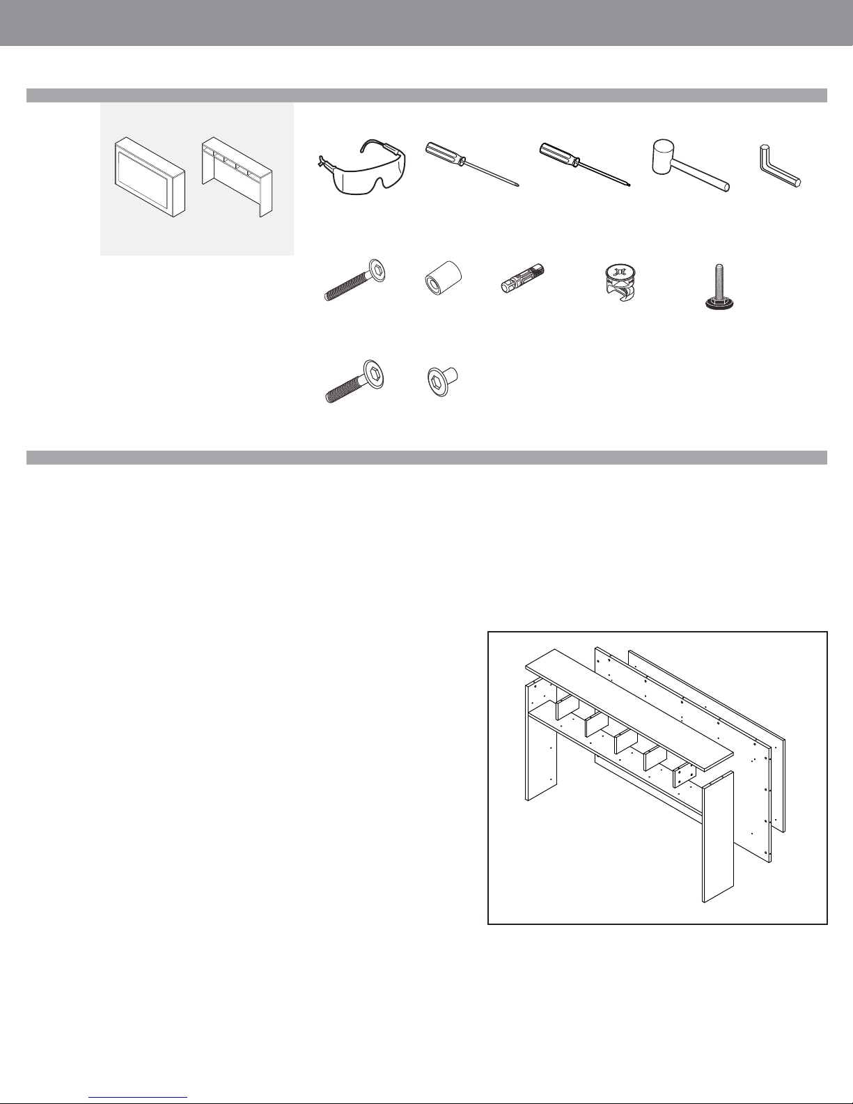
STEP 3: Orient left and right side panels, note that the holes for connectors face
underside of desk with the quick fi x cams to the back.
a. install levellers into T nuts on the bottom of both side gables.
b. Install connecting dowels in pre-drilled holes exposed near back edge
and horizontally to connect lower shelf.
STEP 4: Back panel, Install levellers into T nut inserts on the bottom of the panel.
Orient panel with holes for hardware to the underside of the desk.
a. Install Connecting dowels into row of pre-drilled holes horizontally
approximately 8” from the top.
STEP 5: Pigeon hole lower shelf, line up connecting dowels on back panel to quick
fi x cams on lower shelf. Insure that Quick fi x cams are facing down, turn quick fi x
cam to 2 o’clock position to secure.
STEP 6: Connect the side panels aligning the connecting dowels with the quick fi x
cams. Turn quick fi x cam to 2 o’clock position to secure. Do this to both sides. Lay
assembly down with outside facing up.
STEP 7: There are 6 exposed through holes with routered out “seats” for Spacers.
Place each of the 6 spacers into these positions.
STEP 8: Pick up decorative panel, align installed nutserts on the back of this panel
with the spacers and place into position.
a. From under the assembly, insert the socket screws through exposed
holes and spacers into the T nut inserts on the decorative panel, tighten
using hex wrench.
b. Stand assembly upright.
a. place top panel onto assembly aligning the connecting dowels with the
quick fi x cams. Turn quick fi x cam to 2 o’clock position to secure.
STEP 11: This product is intended to be installed over a standard Licence shell.
Place into position and level both units together.
a. Drill a through hole using a 9.5mm bit though the side panel and gable
on the desk you attaching too. This hole should be centered front to back
and 12-15” from fl oor. Using the Connector Bolt cap and Connector Nut,
secure each side and tighten with hex wrench.
STEP 9: On lower shelf, install connecting dowels and wood dowels. Starting from
left to right , connecting dowels will be used for the fi rst divider, the second panel
will use wood dowels. Continue with pattern.
a. On the top of the shelf dividers, install wood dowels into pre-drilled holes
for divider 2 & 4.
STEP 10: Insert the connecting dowels into the pre-drilled holes on the bottom of
the surface. Note that positions 2 & 4 will connect with wood dowels, do not install
connecting dowels in these corresponding locations.
•Pageglobalcontract.com 26
Page 28
GLOBALContract
INSTALLATION GUIDELINES
3a
• Fall 2017
3b
4
6
5
8a
8b
7
BOLT
SPACER
10
Page • globalcontract.com27
11
Page 29
GLOBALContract
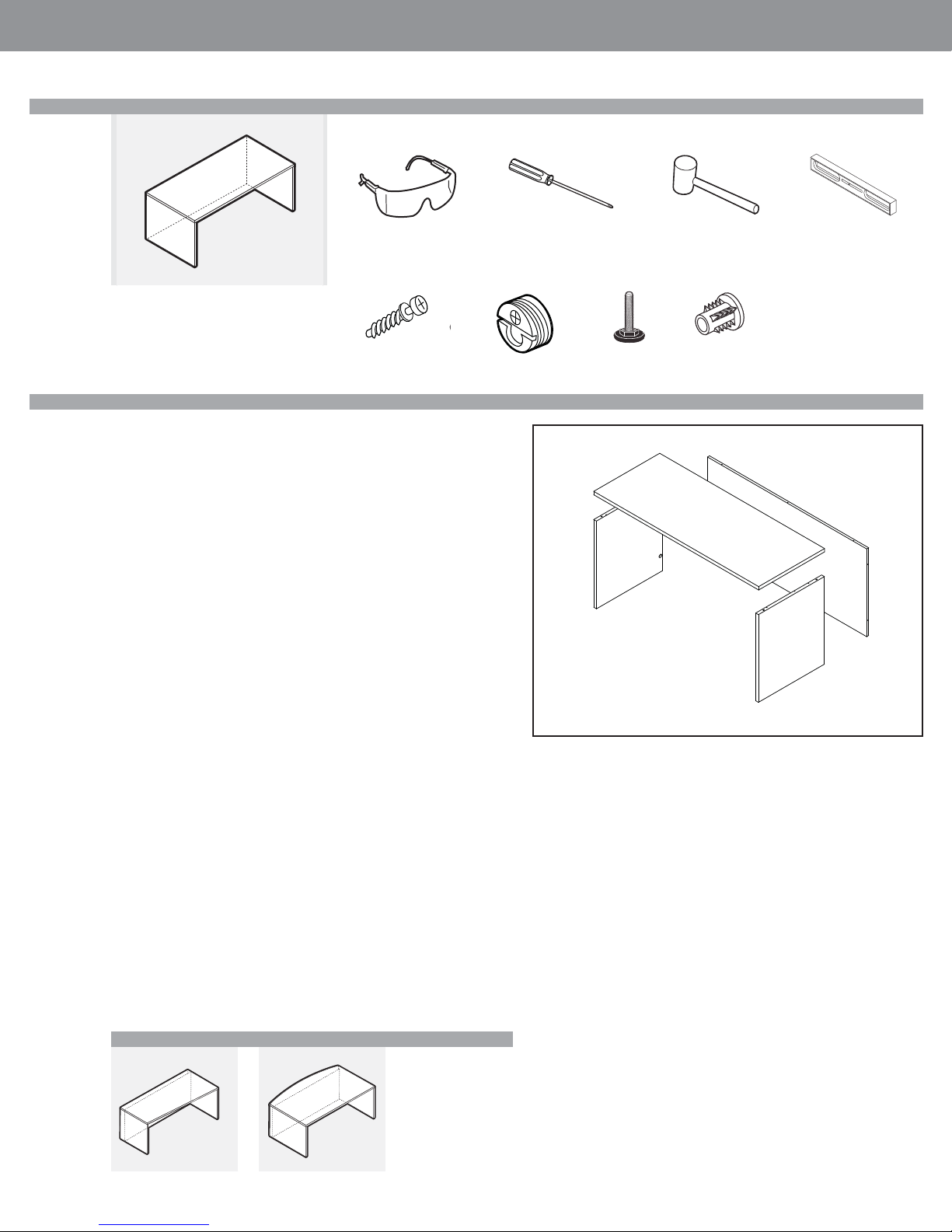
L2CRSxxxx
NOTE: Open and assemble only one product
at a time to avoid a potential mix-up of parts
and hardware.
It is adviseable to assemble the unit on a
carpet to avoid scratches.
Assembly
STEP 1: Unpack and inspect individual pieces for damages or missing hardware
STEP 2: Pick a clean unobstructed area to assemble desk. It is advisable to assembly of this product upside down.
INSTALLATION GUIDELINES
Required Tools
Safety Glasses Rubber Mallet LevelScrewdriver #2 Phillips
Included Hardware
Blum Connector
Screw L005650060
Blum Connector
(installed) L005650061
Leveler
L007250037
• Fall 2017
“T” Nut Insert
L007250039
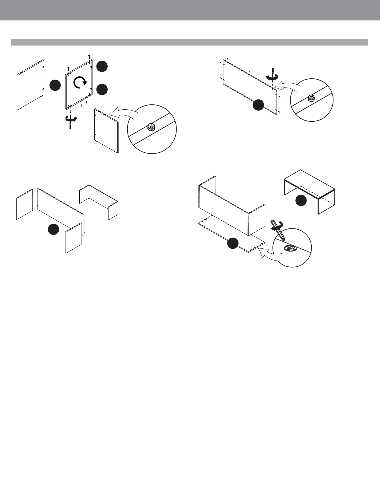
STEP 3: Determine position of left and right gables with exposed Blum connectors
facing inside of assembly.
a. install levellers into the T nut inserts, use mallet to install in pre-drilled
holes on the bottom of the gables.
b. On the top edge, install Blum Connector screws into the pre-drilled
holes. Since the Gables can be used either left or right, 2 holes are pre drilled, select the hole that is closest to underside of completed assembly
to insure proper alignment.
STEP 4: Full Modesty Panel, Install Blum Connector screws in pre-drilled holes on
the top edge and both sides.
STEP 5: Connect gables to the modesty panel by lining up Blum connector screws
with the Blum connectors. Turn the screw on Blum Connector ¼ turn, do not over
tighten.
STEP 6: Place worksurface top face down on clean unobstructed area. Pick up
chassis assembly and line Blum connector screws to the exposed Blum Connectors
on the bottom of the surface. Turn the screw on Blum Connector ¼ turn, do not
over tighten.
STEP 7: Turn product upright. When fi nal position has been located, level the unit
with the levellers installed on both gables.
FULL MODESTYWORKSURFACE
GABLE
GABLE
Installation For Similar Products
L2DBxxxx L2DWxxxxxx
•Pageglobalcontract.com 28
Page 30
GLOBALContract
INSTALLATION GUIDELINES
a
• Fall 2017
LEFT HAND
3
b
RIGHT HAND
Modesty Panel
4
7
5
6
Back Panel
top Underside
Page • globalcontract.com29
Page 31
GLOBALContract
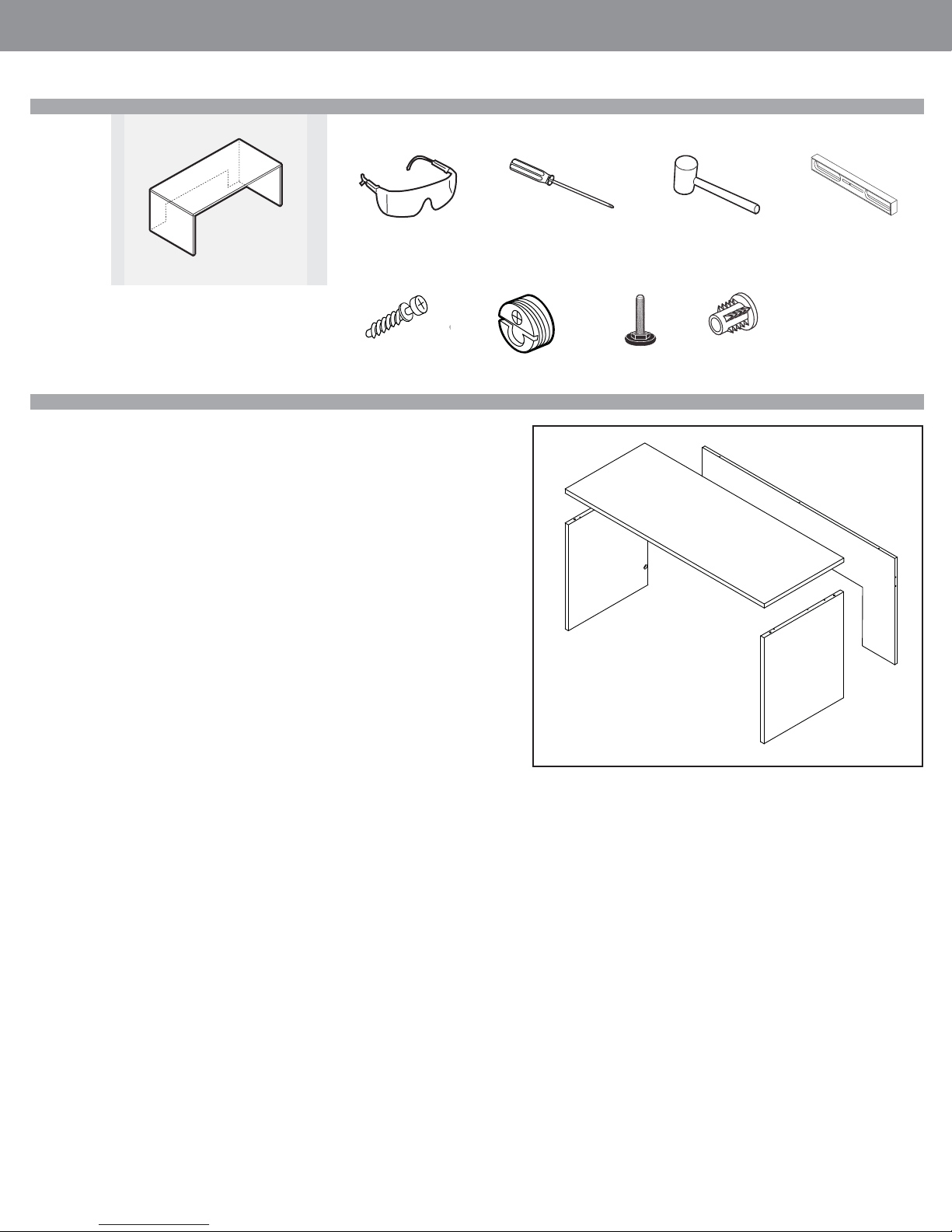
L2CRSHxxxx • L2 Credenza Shell Half Modesty
NOTE: Open and assemble only one product
at a time to avoid a potential mix-up of parts
and hardware.
It is adviseable to assemble the unit on a
carpet to avoid scratches.
Assembly
STEP 1: Unpack and inspect individual pieces for damages or missing hardware
STEP 2: Pick a clean unobstructed area to assemble desk. It is advisable to assembly of this product upside down.
STEP 3: Determine position of left and right gables with exposed Blum connectors
facing inside of assembly.
a. install levellers into the T nut inserts, install into pre-drilled holes on the
bottom of the gable using mallet.
b. On the top edge, install Blum Connector screws into the pre-drilled
holes. Since the Gables can be used either left or right, 2 holes are pre drilled, select the hole that is closest to underside of completed assembly
to ensure proper alignment.
INSTALLATION GUIDELINES
Required Tools
Safety Glasses Rubber Mallet LevelScrewdriver #2 Phillips
Included Hardware
Blum Connector
Screw L005650060
Blum Connector
(installed) L005650061
Leveler
L007250037
GABLE
• Fall 2017
“T” Nut Insert
L007250039
HALF MODESTY
WORKSURFACE
STEP 4: Half modesty panel, install Blum Connector screws in pre-drilled holes
on the top edge and both sides. This panel will attach to single Blum connector on
each side only.
STEP 5: Connect gables to the modesty panel by lining up Blum connector screws
with the Blum connectors. Turn the screw on Blum Connector ¼ turn, do not over
tighten.
STEP 6: Place worksurface top face down on clean unobstructed area. Pick up
chassis assembly and line Blum connector screws to the exposed Blum Connectors
on the bottom of the surface. Turn the screw on Blum Connector ¼ turn, do not
over tighten.
STEP 7: Turn product upright. When fi nal position has been located, level the unit
with the levellers installed on both gables.
GABLE
•Pageglobalcontract.com 30
Page 32
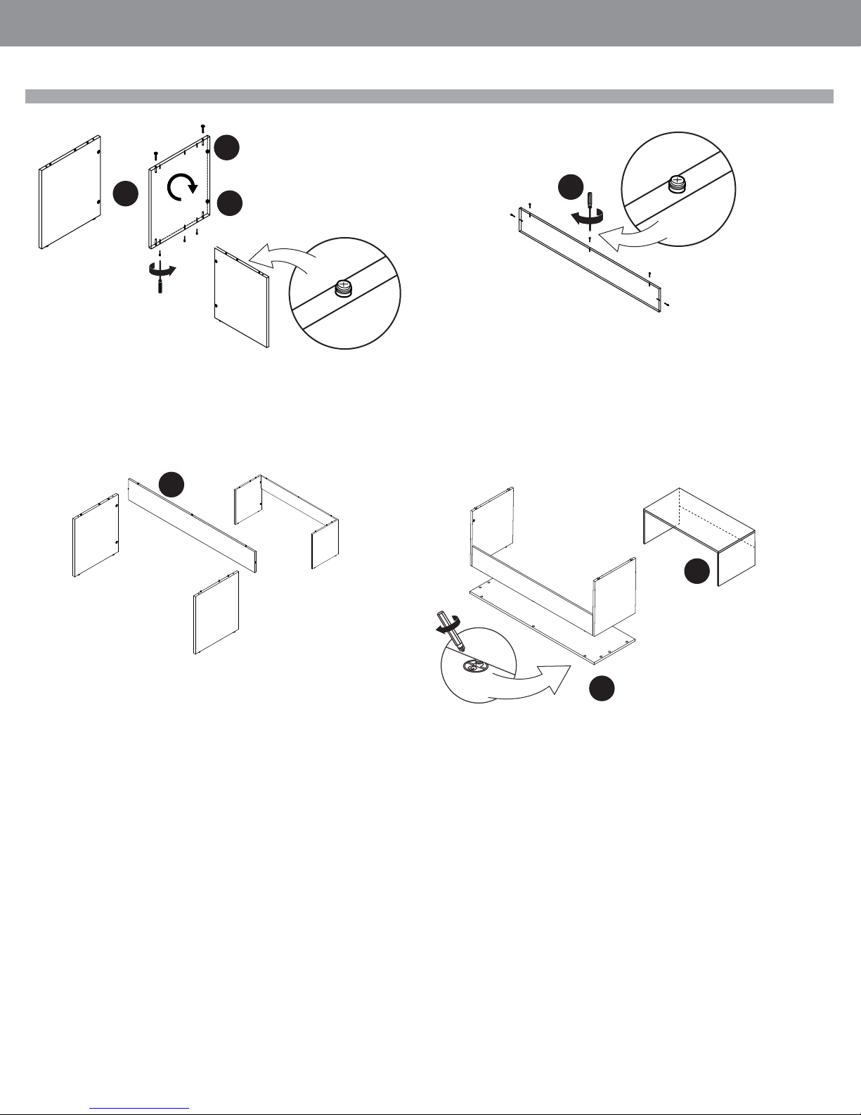
GLOBALContract
INSTALLATION GUIDELINES
a
• Fall 2017
LEFT HAND
3
b
RIGHT HAND
4
5
7
Back Panel
Top Underside
6
Page • globalcontract.com31
Page 33
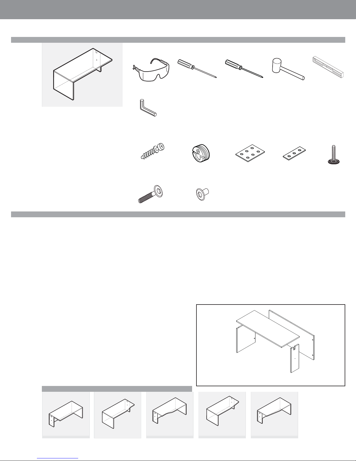
GLOBALContract
L2RCxxxxL
NOTE: Open and assemble only one product
at a time to avoid a potential mix-up of parts
and hardware.
It is adviseable to assemble the unit on a
carpet to avoid scratches.
Required Tools
Safety Glasses
#4 & 5 Hex Wrench
Included Hardware
Blum Connector
Screw L005650060
• Fall 2017
INSTALLATION GUIDELINES
Screwdriver #2 Phillips Rubber MalletScrewdriver Roberson Level
Blum Connector
(installed) L005650061
Flat Bracket
L005650025
Flat Bracket
L005651035
Leveler
L007250037
Connector Bolt
L005650114
Connector Nut
L005650117
Assembly
STEP 1: Unpack and inspect individual pieces for damages or missing hardware
STEP 2: Pick a clean unobstructed area to assemble desk. It is advisable to assembly of this product upright.
STEP 3: Determine position of left and right gables as this will determine position
of hardware.
a. Full gable is position on the left hand with exposed Blum connectors
facing to inside of assembly.
b. Narrow Gable is positioned on the right hand side of the assembly with
holes on the back edge.
STEP 4: Install Blum connector screws on the top edge of the narrow gable, note
that there are two holes in this position, select the hole closest to the underside of
the assembly to insure correct alignment.
a. On the large gable, install Blum connector screws on top edge, note that
there are two holes in this position, select the hole closest to the underside
of the assembly to insure correct alignment.
b. Install levelers into T nuts, using mallet to install into pre-drilled holes on
the bottom of the gable.
STEP 5: Install Levellers on the bottom of both gables into the T nuts pre installed.
tor screws into the Blum Connectors. Tighten Blum connecter ¼ turn, do
not over tighten.
STEP 7: With the Worksurface laying upside down on the fl oor, Pick up chassis
assembly lining up Blum connecter screws to the Blum connectors installed on the
bottom of the surface. Tighten Blum connecter ¼ turn, do not over tighten.
STEP 8: Stand completed assembly upright.
STEP 9: Using the provided #8 x ¾ wood screws, secure fl at brackets to the underside of adjoining surfaces. The half fl at bracket is to be installed in the “cableway”
opening in the narrow gable. Install full fl at bracket half way between front edge of
surface and the front edge of the half Gable.
a. Connecter screw and nut will be used to gang narrow gable to narrow
gable of adjoining assembly using hex wrench.
FULL MODESTY
WORKSURFACE
GABLE
STEP 6: Orient to modesty panel so that the Blum Connectors on the face line up
with the end where narrow gable will be installed.
a. Connect the gables to the modesty panel by lining up the Blum connec
Installation For Similar Products
L2RCxxxxR L2RCSxxxx L2RCSxxxxxx L2RCWxxxxxx L2RCWxxxxxx
NARROW GABLE
•Pageglobalcontract.com 32
Page 34
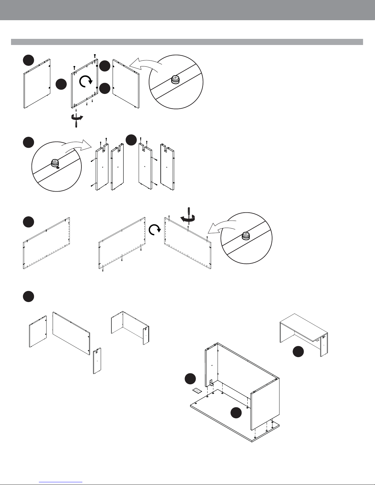
GLOBALContract
INSTALLATION GUIDELINES
• Fall 2017
3a
4a
4
LEFT HAND RIGHT HAND
4
LEFT HAND APPLICATION RIGHT HAND APPLICATION
4b
3b
6
LEFT HAND RETURN CONNECTING
6a
Note: Follow the same directions for the right hand of
the application.
RIGHT HAND RETURN CONNECTING
8
9
7
Page • globalcontract.com33
Page 35
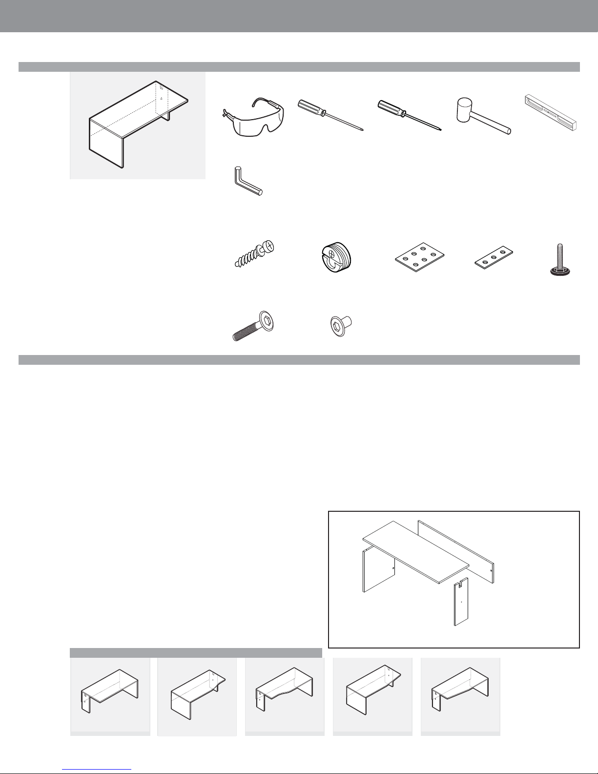
GLOBALContract
L2RCHxxxxL
NOTE: Open and assemble only one product
at a time to avoid a potential mix-up of parts
and hardware.
It is adviseable to assemble the unit on a
carpet to avoid scratches.
Required Tools
Safety Glasses
#4 & 5 Hex Wrench
Included Hardware
Blum Connector
Screw L005650060
• Fall 2017
INSTALLATION GUIDELINES
Screwdriver #2 Phillips Rubber MalletScrewdriver Roberson Level
Blum Connector
(installed) L005650061
Flat Bracket
L005650025
Flat Bracket
L005651035
Leveler
L007250037
Connector Bolt
L005650114
Connector Nut
L005650117
Assembly
STEP 1: Unpack and inspect individual pieces for damages or missing hardware
STEP 2: Pick a clean unobstructed area to assemble desk. It is advisable to assembly of this product upright.
STEP 3: determine position of left and right gables as this will determine position of
hardware.
a. Full gable is position on the left hand with exposed Blum connectors
facing to inside of assembly.
b. Narrow Gable is positioned on the right hand side of the assembly with
holes on the back edge.
STEP 4: Install Blum connector screws on the top edge of the narrow gable, note
that there are two holes in this position, select the hole closest to the underside of
the assembly to insure correct alignment.
a. On the large gable, install Blum connector screws on top edge, note that
there are two holes in this position, select the hole closest to the underside
of the assembly to insure correct alignment.
b. Install levelers into T nuts, using mallet to install into pre-drilled holes on
the bottom of the gable.
STEP 5: Install Levellers on the bottom of both gables into the T nuts pre installed.
not over tighten.
STEP 7: With the Worksurface laying upside down on the fl oor, Pick up chassis
assembly lining up Blum connecter screws to the Blum connectors installed on the
bottom of the surface. Tighten Blum connecter ¼ turn, do not over tighten.
STEP 8: Stand completed assembly upright.
STEP 9: Using the provided #8 x ¾ wood screws, secure fl at brackets to the underside of adjoining surfaces. The half fl at bracket is to be installed in the “cableway”
opening in the narrow gable. Install full fl at bracket half way between front edge of
surface and the front edge of the half Gable.
a. Connecter screw and nut will be used to gang narrow gable to narrow
gable of adjoining assembly using hex wrench.
FULL MODESTY
WORKSURFACE
GABLE
STEP 6: Orient to modesty panel so that the Blum Connector on the face line up
with the end where narrow gable will be installed.
a. Connect the gables to the modesty panel by lining up the Blum connec
tor screws into the Blum Connectors. Tighten Blum connecter ¼ turn, do
Installation For Similar Products
L2RCxxxxR L2RCSxxxx L2RCSxxxxxx L2RCWxxxxxx L2RCWxxxxxx
NARROW GABLE
•Pageglobalcontract.com 34
Page 36
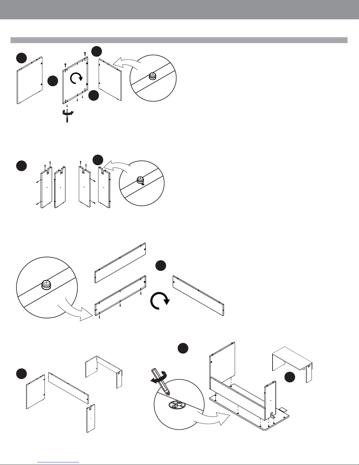
GLOBALContract
INSTALLATION GUIDELINES
4a
3a
4
4b
LEFT HAND RIGHT HAND
3b
4
• Fall 2017
LEFT HAND APPLICATION RIGHT HAND APPLICATION
6a
6
RIGHT HAND RETURN
CONNECTING
7
8
Page • globalcontract.com35
Back Panel
Top Underside
Page 37
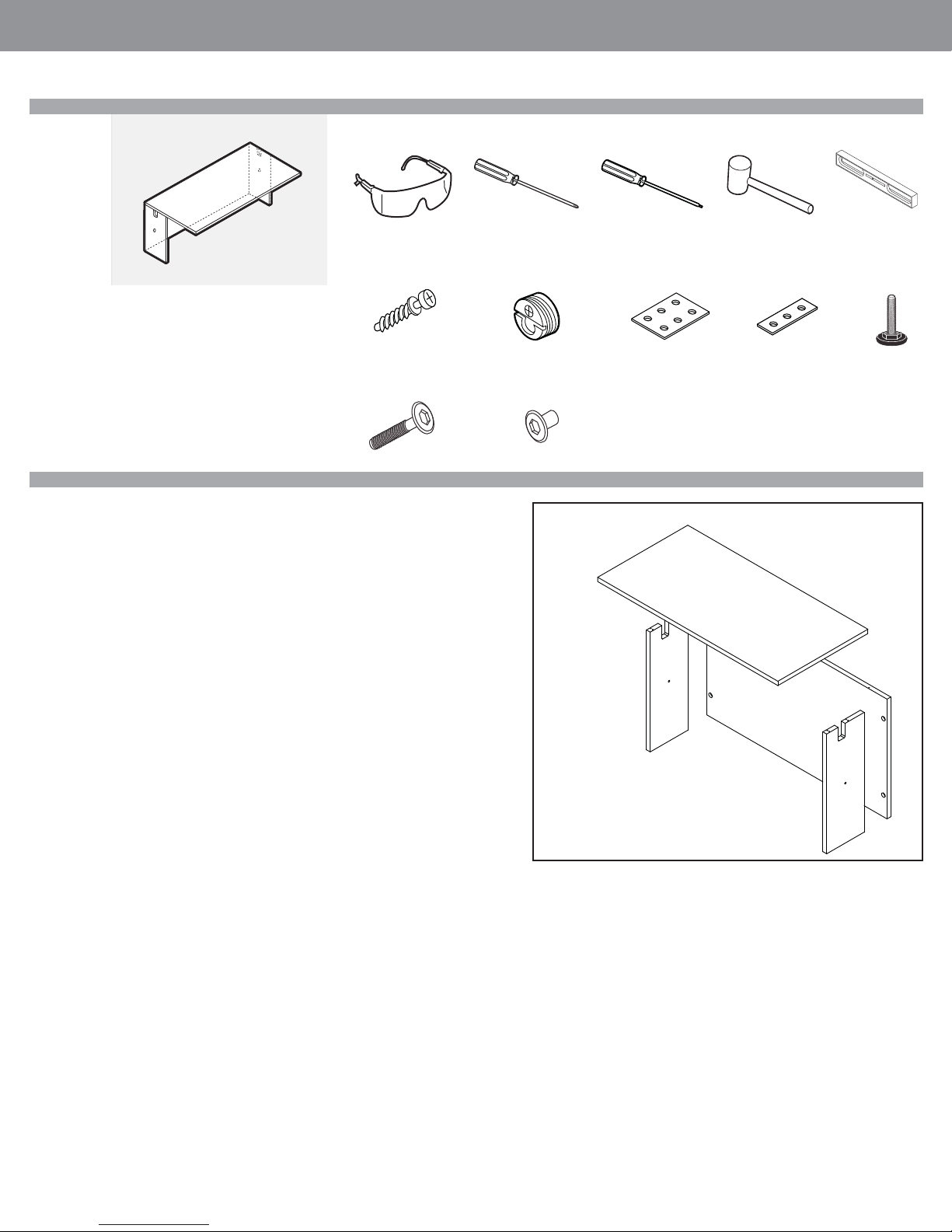
GLOBALContract
L2RCxxxxC
NOTE: Open and assemble only one product
at a time to avoid a potential mix-up of parts
and hardware.
It is adviseable to assemble the unit on a
carpet to avoid scratches.
Required Tools
Safety Glasses
Included Hardware
Blum Connector
Screw L005650060
Connector Bolt
L005650114
• Fall 2017
INSTALLATION GUIDELINES
Screwdriver #2 Phillips Rubber MalletScrewdriver Roberson Level
Blum Connector
(installed) L005650061
Connector Nut
L005650117
Flat Bracket
L005650025
Flat Bracket
L005651035
Leveler
L007250037
Assembly
STEP 1: Unpack and inspect individual pieces for damages or missing hardware
STEP 2: Pick a clean unobstructed area to assemble desk. It is advisable to assembly of this product upright.
STEP 3: Determine Left and right gables. Install levellers into T nuts provided on the
bottom of both gables.
a. Installing the Blum Connecter Screws on top and back edge. Each gable
will have 2 holes for each Blum connecter screw. Based on position of the
gable, use pre-drilled hole closest to the underside of the desk to insure
correct alignment with the Blum connectors on modesty panel and Worksurface.
STEP 4: Modesty panel. Install Blum Connecter screws in pre-drilled holes on top
edge of the Modesty.
a. Connect gables to Modesty panel by lining up Installed Blum connector
screws on the gables to the Blum connectors on the modesty panel.
Tighten Blum connectors ¼ turn, do not over tighten.
STEP 5: With the Worksurface laying upside down on the fl oor, Pick up chassis
assembly lining up Blum connecter screws to the Blum connectors installed on the
bottom of the surface. Tighten Blum connecter ¼ turn, do not over tighten.
STEP 6: Stand completed assembly upright and you are ready to install.
STEP 7: Using the provided #8 x ¾ wood screws, secure fl at brackets to the underside of adjoining surfaces. The half fl at bracket is to be installed in the “cableway”
opening in the narrow gable. Install full fl at bracket half way between front edge of
surface and the front edge of the half Gable.
a. Connecter bolt and nut will be used to gang narrow gable to narrow
gable of adjoining assembly using hex wrench.
WORKSURFACE
NARROW GABLE
FULL MODESTY
NARROW GABLE
•Pageglobalcontract.com 36
Page 38
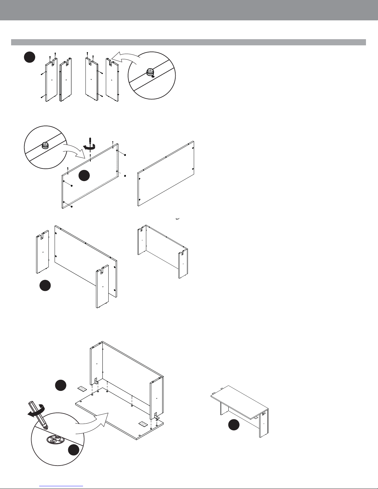
GLOBALContract
INSTALLATION GUIDELINES
3
LEFT HAND APPLICATION RIGHT HAND APPLICATION
4
• Fall 2017
4a
Top Underside
7
Back Panel
6
5
Page • globalcontract.com37
Page 39
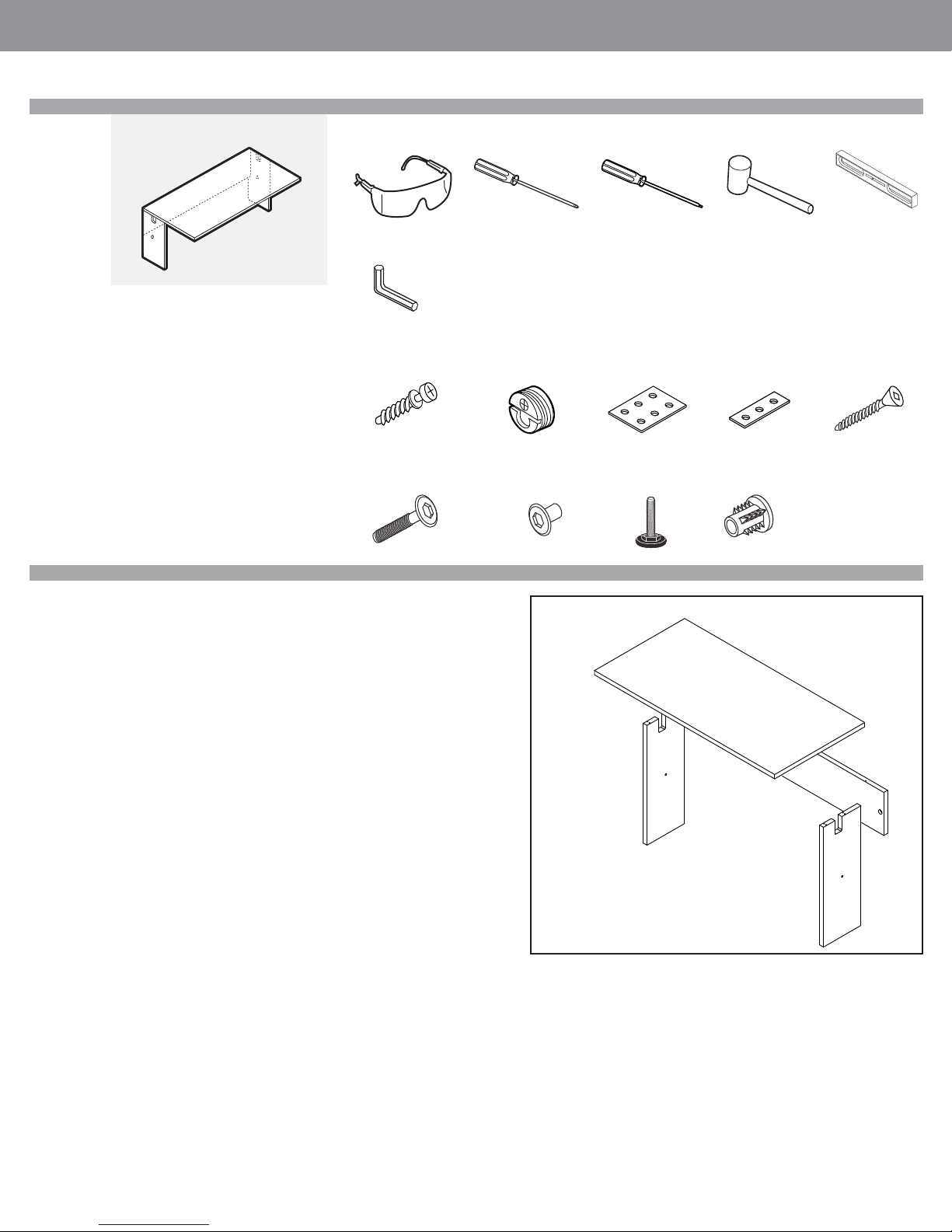
GLOBALContract
L2RCHxxxxC
NOTE: Open and assemble only one product
at a time to avoid a potential mix-up of parts
and hardware.
It is adviseable to assemble the unit on a
carpet to avoid scratches.
Required Tools
Safety Glasses
#4 & 5 Hex Wrench
Included Hardware
Blum Connector
Screw L005650060
• Fall 2017
INSTALLATION GUIDELINES
Screwdriver #2 Phillips Rubber MalletScrewdriver Roberson Level
Blum Connector
(installed) L005650061
Flat Bracket
L005650025
Flat Bracket
L005651035
Wood Screw #8 3/4
L007250032
Connector Bolt
L005650114
Connector Nut
L005650117
Assembly
STEP 1: Unpack and inspect individual pieces for damages or missing hardware
STEP 2: Pick a clean unobstructed area to assemble desk. It is advisable to assembly of this product upright.
STEP 3: Determine Left and right gables. Install levellers into T nuts provided on the
bottom of both gables.
a. Installing the Blum Connecter Screws on top and back edge. Each gable
will have 2 holes for each Blum connecter screw. Based on position of the
gable, use pre-drilled hole closest to the underside of the desk to insure
correct alignment with the Blum connectors on modesty panel and Worksurface.
STEP 4: Modesty panel. Install Blum Connecter screws in pre-drilled holes on top
edge of the Modesty.
a. Connect gables to Modesty panel by lining up Installed Blum connector
screws on the gables to the Blum connectors on the modesty panel.
Tighten Blum connectors ¼ turn, do not over tighten.
STEP 5: With the Worksurface laying upside down on the fl oor, Pick up chassis
assembly lining up Blum connecter screws to the Blum connectors installed on the
bottom of the surface. Tighten Blum connecter ¼ turn, do not over tighten.
NARROW GABLE
Leveler
L007250037
WORKSURFACE
“T” Nut Insert
L007250039
HALF MODESTY
NARROW GABLE
STEP 6: Stand completed assembly upright and you are ready to install.
STEP 7: Using the provided #8 x ¾ wood screws, secure fl at brackets to the underside of adjoining surfaces. The half fl at bracket is to be installed in the “cableway”
opening in the narrow gable. Install full fl at bracket half way between front edge of
surface and the front edge of the half Gable.
a. Connecter bolt and nut will be used to gang narrow gable to narrow
gable of adjoining assembly using hex wrench.
•Pageglobalcontract.com 38
Page 40
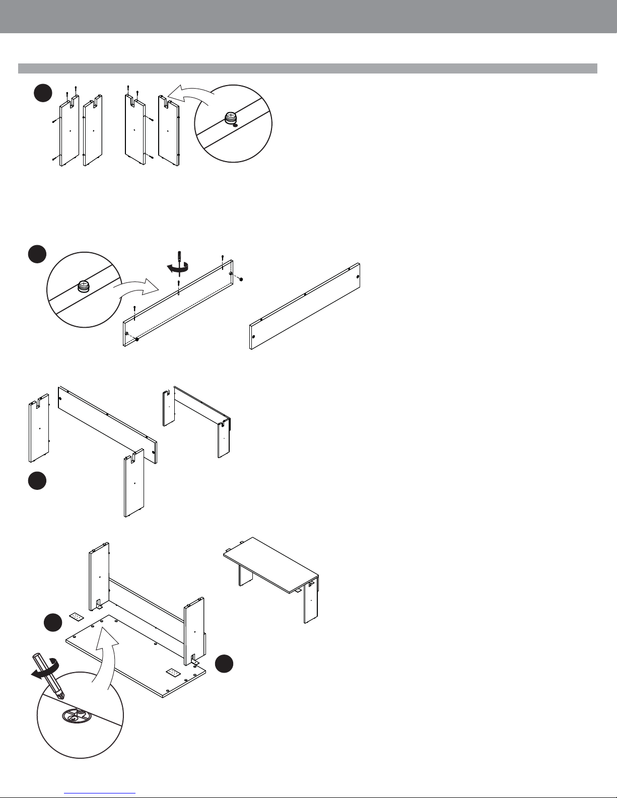
GLOBALContract
INSTALLATION GUIDELINES
3
LEFT HAND APPLICATION RIGHT HAND APPLICATION
RETURN CONNECTING (b)
HALF MODESTY PANEL
4
• Fall 2017
5
7
6
Back Panel
Top Underside
Page • globalcontract.com39
Page 41
GLOBALContract
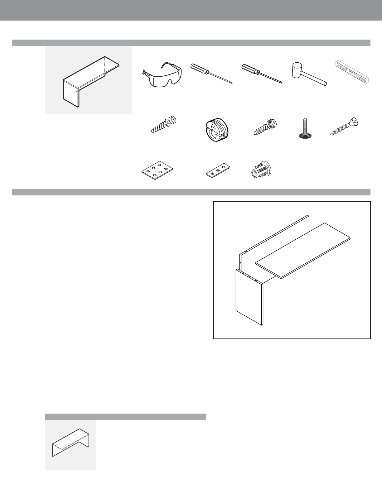
L2ER_R / L2ER_L • L2 Executive Return Left or Right
NOTE: Open and assemble only one product
at a time to avoid a potential mix-up of parts
and hardware.
It is adviseable to assemble the unit on a
carpet to avoid scratches.
Required Tools
Safety Glasses
Included Hardware
Blum Connector
Screw L005650060
Flat Bracket
L005650025
• Fall 2017
INSTALLATION GUIDELINES
Screwdriver #2 Phillips Rubber MalletScrewdriver Roberson Level
Blum Connector
(installed) L005650061
Flat Bracket
L005651035
Modular Screw
L007250001
“T” Nut Insert
L007250039
Leveler
L007250037
Wood Screw #8 3/4
L007250032
Assembly
STEP 1: Unpack and inspect individual pieces for damages or missing hardware
STEP 2: Pick a clean unobstructed area to assemble desk. It is advisable to assembly of this product upright.
STEP 3: Determine placement of the gable, the gable can be used as both left and
right. Base on the application orient gable with exposed Blum connectors to the
back.
a. Install levellers into T nuts provided on the bottom of gable.
b. Installing the Blum Connecter Screws on top and back edge.
STEP 4: Modesty panel. Install Blum Connecter screws in pre-drilled holes on top
edge of the Modesty.
a. Install Blum connector screws on edge of gable that lines up with the gable.
b. Connect gable to Modesty panel to the gable by lining up connector
screws with the Blum Connectors. Tighten Blum connectors ¼ turn, do
not over tighten.
STEP 5: With the Worksurface laying upside down on the fl oor, Pick up chassis
assembly lining up Blum connecter screws to the Blum connectors installed on
the bottom of the surface. Tighten Blum connecter ¼ turn, do not over tighten.
STEP 6: Stand completed assembly upright and you are ready to install.
STEP 7: This unit is intended to be attached to an adjoining assembled unit at the
open end using the provided Flat Brackets. The Flat Brackets are screwed into
ganged assemblies at the worksurface joint using #8 x ¾ wood screws.
FULL MODESTY
WORKSURFACE
GABLE
STEP 8: When fi nal position has been located, level the unit with the levellers
installed on the pedestal.
Installation For Similar Products
L2DRxxxxBF
•Pageglobalcontract.com 40
Page 42
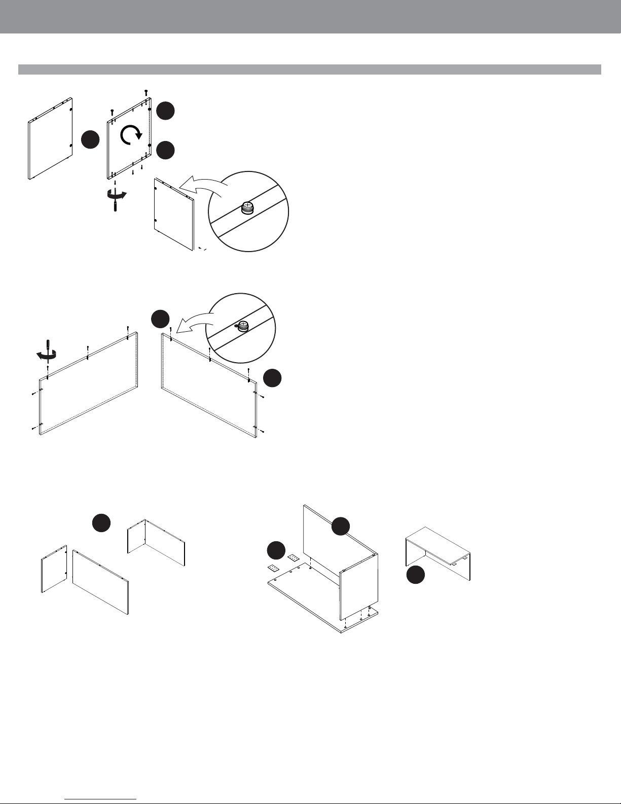
GLOBALContract
INSTALLATION GUIDELINES
3a
3
3b
LEFT HAND
RIGHT HAND
• Fall 2017
4a
FULL MODESTY PANEL
LEFT HAND APPLICATION RIGHT HAND APPLICATION
4b
4
5
7
8
Page • globalcontract.com41
Page 43
GLOBALContract
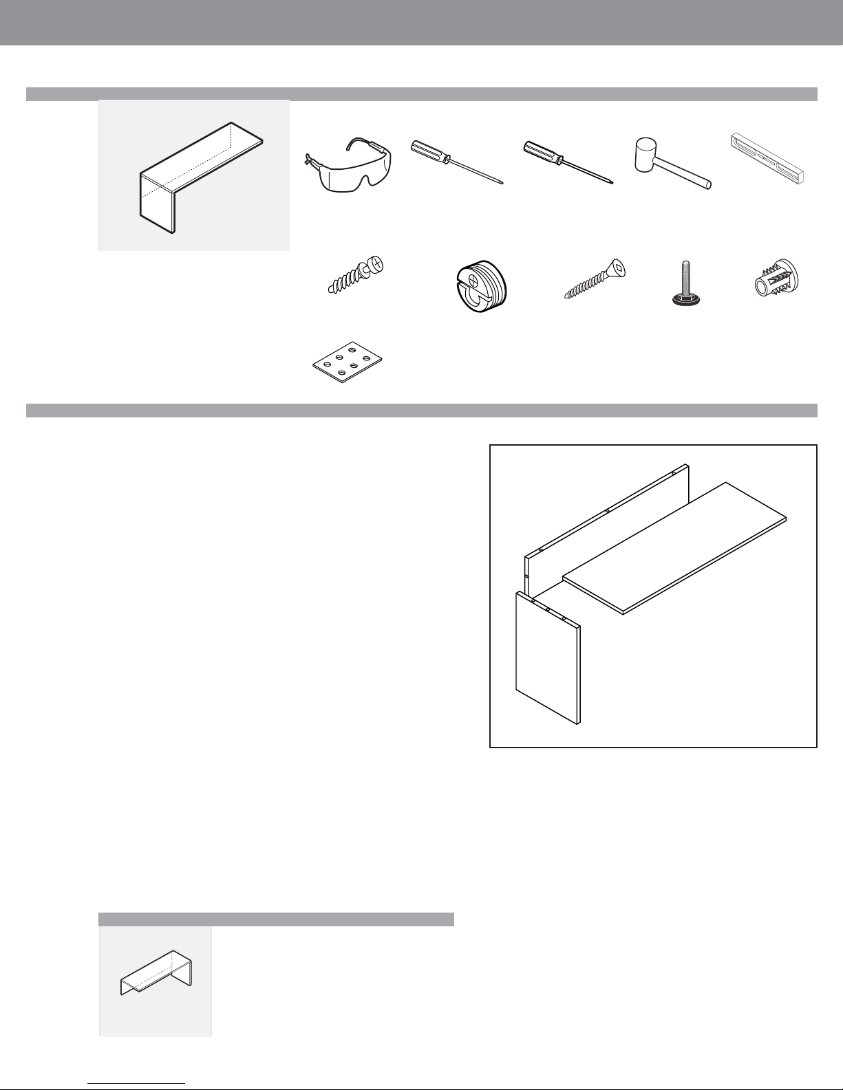
L2ERH-L
NOTE: Open and assemble only one product
at a time to avoid a potential mix-up of parts
and hardware.
Required Tools
Safety Glasses
Included Hardware
Blum Connector
Screw L005650060
• Fall 2017
INSTALLATION GUIDELINES
Screwdriver #2 Phillips Rubber MalletScrewdriver Roberson Level
Blum Connector
(installed) L005650061
Wood Screw #8 3/4
L007250032
Leveler
L007250037
“T” Nut Insert
L007250039
It is adviseable to assemble the unit on a
carpet to avoid scratches.
Flat Bracket
L005650025
Assembly
STEP 1: Unpack and inspect individual pieces for damages or missing hardware
STEP 2: Pick a clean unobstructed area to assemble desk. It is advisable to assembly of this product upright.
STEP 3: Determine placement of the gable, the gable can be used as both left and
right. Base on the application orient gable with exposed Blum connectors to the back.
a. Install levellers into T nuts, using mallet install into pre-drilled holes on
the bottom of gable.
b. Installing the Blum Connecter Screws on top and back edge.
STEP 4: Modesty panel. Install Blum Connecter screws in pre-drilled holes on top
edge of the Modesty.
a. Install Blum connector screws on edge of modesty that lines up with the gable.
b. Connect gable to modesty panel to the gable by lining up connector
screws with the Blum Connectors. Tighten Blum connectors ¼ turn, do not
over tighten.
STEP 5: With the Worksurface laying upside down on the fl oor, Pick up chassis
assembly lining up Blum connecter screws to the Blum connectors installed on the
bottom of the surface. Tighten Blum connecter ¼ turn, do not over tighten.
HALF MODESTY
WORKSURFACE
GABLE
STEP 6: Stand completed assembly upright and you are ready to install.
STEP 8. This unit is intended to be attached to an adjoining assembled unit at the
open end using the provided Flat Brackets. The Flat Brackets are screwed into
ganged assemblies at the worksurface joint using #8 x ¾ wood screws.
STEP 9: When fi nal position has been located, level the unit with the levellers
installed on the pedestal.
Installation For Similar Products
L2ERHxxxxR
•Pageglobalcontract.com 42
Page 44
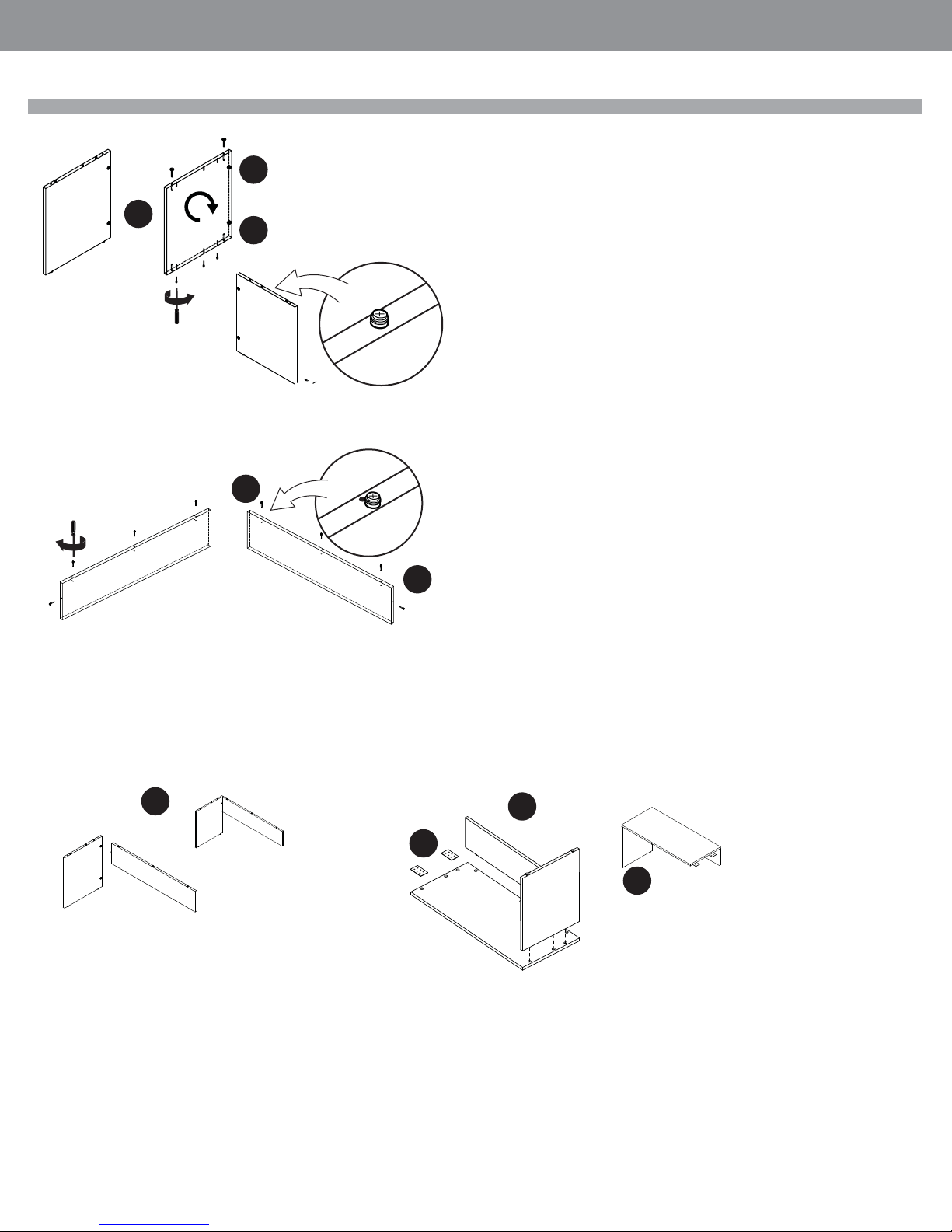
GLOBALContract
INSTALLATION GUIDELINES
3a
3
3b
LEFT HAND
RIGHT HAND
• Fall 2017
4a
Back Panel (c)
LEFT HAND APPLICATION RIGHT HAND APPLICATION
4b
4
5
7
8
Page • globalcontract.com43
Page 45
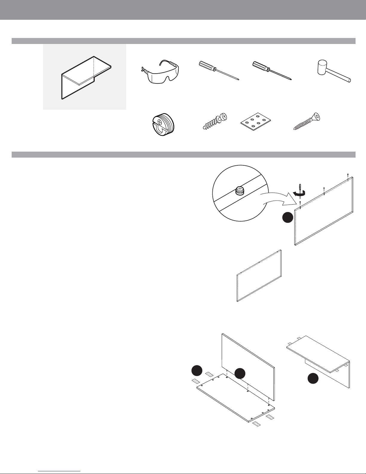
GLOBALContract
L2Bxxxx
NOTE: Open and assemble only one product
at a time to avoid a potential mix-up of parts
and hardware.
It is adviseable to assemble the unit on a
carpet to avoid scratches.
Assembly
STEP 1: Unpack and inspect individual pieces for damages or missing hardware.
STEP 2: Pick a clean unobstructed are to assemble desk. It is advisable to do fi nal
assembly upside down.
• Fall 2017
INSTALLATION GUIDELINES
Required Tools
Safety Glasses Rubber Mallet
Included Hardware
Blum Connector
(installed) L005650061
Screwdriver #2 Phillips
Blum Connector
Screw L005650060
Screwdriver #2 Roberson
Flat Bracket
L005650025
Wood Screw #8 3/4
L007250032
STEP 3: Modesty panel. Install Blum Connecter screws in pre-drilled holes on top
edge of the Modesty.
STEP 4: With the worksurface laying upside down on the fl oor, Pick up modesty
lining up Blum connecter screws to the Blum connectors installed on the bottom of
the surface. Tighten Blum connecter ¼ turn, do not over tighten.
STEP 5: Stand completed assembly upright and you are ready to install.
STEP 6: This unit is intended to be attached to adjoining assembled units on both
ends the provided Flat Brackets. The Flat Brackets are screwed into ganged assemblies at the worksurface joint using #8 x ¾ wood screws.
3
WORKSURFACE
6
4
5
FULL MODESTY
•Pageglobalcontract.com 44
Page 46

GLOBALContract
INSTALLATION GUIDELINES
• Fall 2017
Page • globalcontract.com45
Page 47
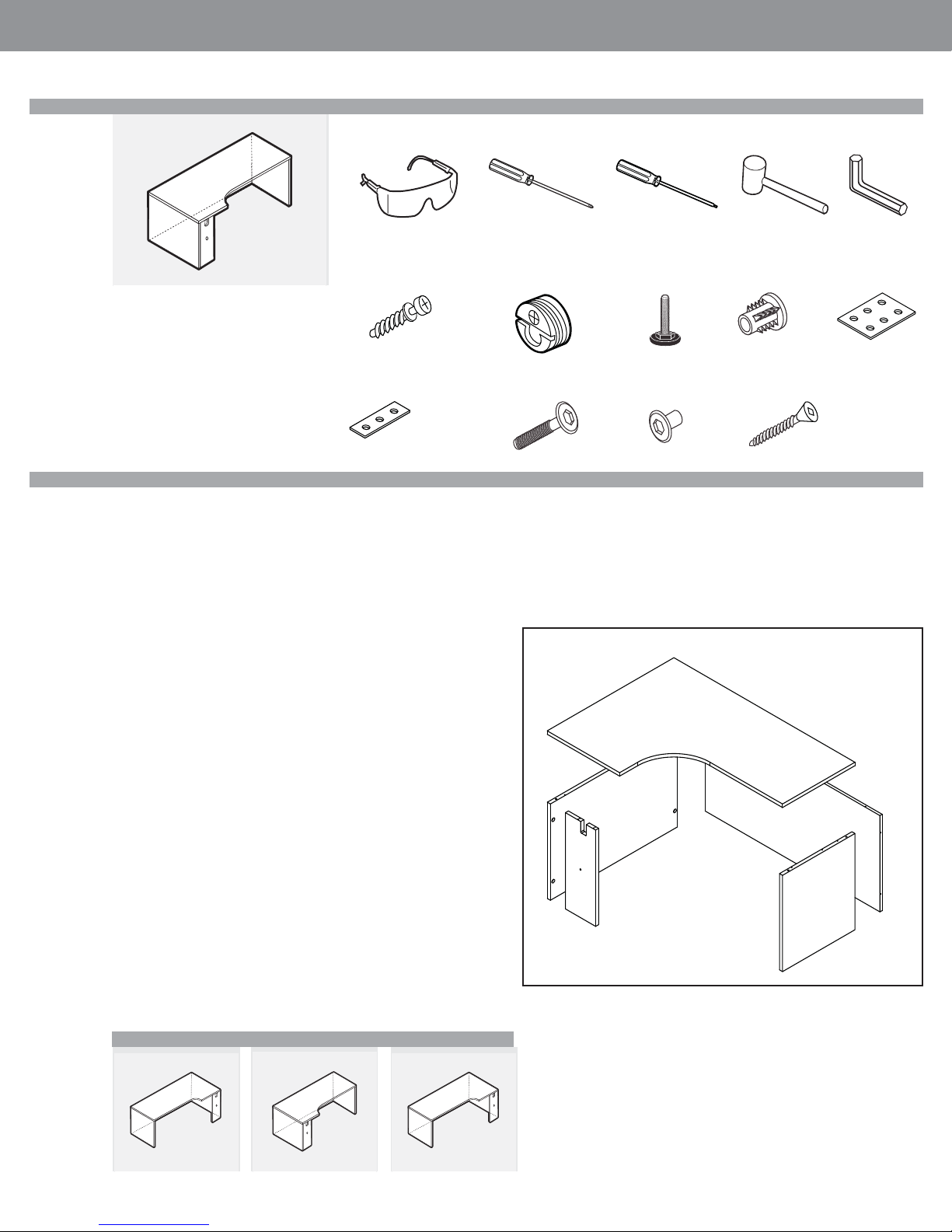
GLOBALContract
L2ECxxxxxxR
NOTE: Open and assemble only one product
at a time to avoid a potential mix-up of parts
and hardware.
It is adviseable to assemble the unit on a
carpet to avoid scratches.
INSTALLATION GUIDELINES
Required Tools
Safety Glasses Hex WrenchScrewdriver #2 Phillips Rubber MalletScrewdriver Roberson
Included Hardware
Blum Connector
Screw L005650060
Bracket
L005651035
Blum Connector
(installed) L005650061
Connector Bolt
L005650114
Leveler
L007250037
Connector Nut
L005650117
“T” Nut Insert
L007250039
Wood Screw #8 3/4
L007250032
• Fall 2017
Flat Bracket
L005650025
Assembly
STEP 1: Unpack and inspect individual pieces for damages or missing hardware.
STEP 2: Pick a clean unobstructed area to assemble desk. This unit is best to assemble upside down.
STEP 3: Determine position of left and right gables as this will determine position
of hardware.
a. Orient partial gable so that exposed holes are on back edge. Install levellers
into T nuts, using mallet install into pre-drilled holes on the bottom of gable.
Install Blum connector screws on the top and back edge into pre-drilled
holes. Note that 2 holes are available in each position, install in hole closest
to underside of the desk.
b. End gable connecting, orient with Blum connectors facing inside of desk
Install levellers into T nuts, using mallet install into pre-drilled holes on the
bottom of gable. Install Blum connector screws on the top and back edge
into pre-drilled holes. Note that 2 holes are available in each position, install
in hole closest to underside of the desk.
c. Full modesty panel. Install Blum connector screws on the top and back
edge into pre-drilled holes.
d. Full end gable, orient with Blum connectors facing inside of desk. Install
levellers into T nuts on bottom of gable. Install Blum connector screws on
the top and back edge into pre-drilled holes. Note that 2 holes are available
in each position, install in hole closest to underside of the desk.
STEP 4: Connect chassis together by lining up Blum connectors with Blum connector screws on adjoining pieces. Tighten Blum connectors ¼ turn, do not over
tighten.
STEP 5: Lay worksuface on fl oor with Blum connectors facing up. Install assembled
chassis by lining up Blum connector screws with the Blum connectors on the
worksurface top. Tighten Blum connectors ¼ turn, do not over tighten.
STEP 6: Stand completed assembly upright.
STEP 7: Using the provided #8 x ¾ wood screws, secure fl at brackets to the underside of adjoining surfaces. The half fl at bracket is to be installed in the “cableway”
opening in the narrow gable. Install full fl at bracket half way between front edge of
surface and the front edge of the half Gable.
a. Connecter nolt and nut will be used to gang narrow gable to narrow
gable of adjoining assembly using hex wrench.
WORKSURFACE
GABLE
FULL MODESTY
NARROW GABLE
GABLE
Installation For Similar Products
L2ECxxxxxxL L2ECxxxxxxR L2ECxxxxxxL
•Pageglobalcontract.com 46
Page 48
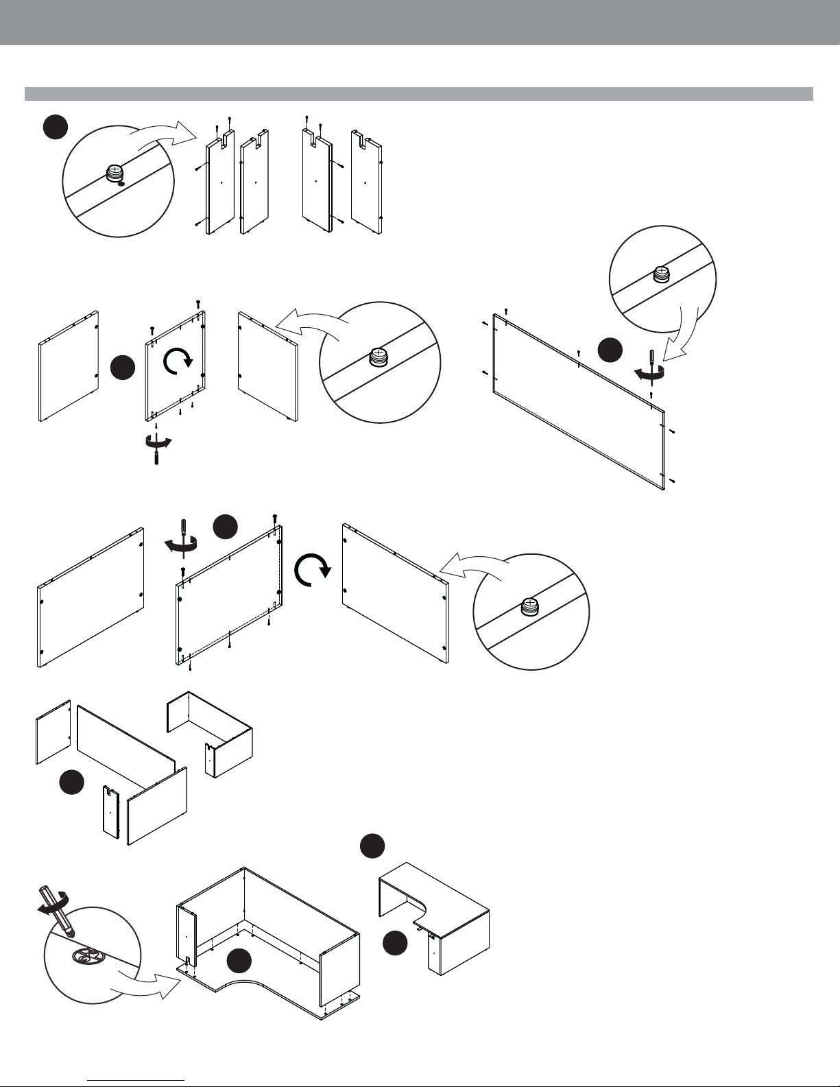
GLOBALContract
INSTALLATION GUIDELINES
3a
LEFT HAND APPLICATION RIGHT HAND APPLICATION
3b
• Fall 2017
3c
LEFT HAND RIGHT HAND
LEFT HAND RIGHT HAND
3d
4
Back Panel
Top Underside
5
Page • globalcontract.com47
6
7
Page 49
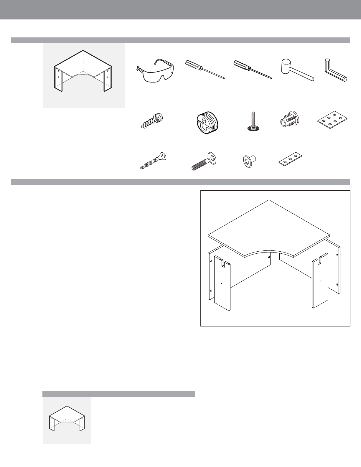
GLOBALContract
L2CC
NOTE: Open and assemble only one product
at a time to avoid a potential mix-up of parts
and hardware.
It is adviseable to assemble the unit on a
carpet to avoid scratches.
• Fall 2017
INSTALLATION GUIDELINES
Required Tools
Safety Glasses Hex Wrench
Included Hardware
Blum Connector
Screw L005650060
Wood Screw #8 3/4
L007250032
Screwdriver #2 Phillips Rubber MalletScrewdriver Roberson
Blum Connector
(installed) L005650061
Connector Bolt
L005650114
Leveler
L007250037
Connector Nut
L005650117
“T” Nut Insert
L007250039
Flat Bracket
L005651035
Flat Bracket
L005650025
Assembly
STEP 1: Unpack and inspect individual pieces for damages or missing hardware.
STEP 2: Pick a clean unobstructed area to assemble desk. This unit is best to assemble upside down.
STEP 3: Determine position of left and right gables as this will determine position
of hardware.
a. Partial gables, orient so that exposed holes are on the back edge Install
levellers into T nuts, using mallet install into pre-drilled holes on the bottom
of gable. Install Blum connector screws on the top and back edge into pre drilled holes. Note that 2 holes are available in each position, install in hole
closest to underside of the desk.
b. Back panel one. Orient with Blum connectors facing inside of desk so
that exposed Blum connecotrs line up with Narrow gable Install levellers
into T nuts, using mallet install into pre-drilled holes on the bottom of
gable. Install Blum connector screws on the top and side edge opposite
Blum connectors, into pre-drilled holes.
STEP 4: Connect chassis together by lining up Blum connectors with Blum connector screws on adjoining pieces. Tighten Blum connectors ¼ turn, do not over
tighten.
STEP 5: Lay worksuface on fl oor with Blum connectors facing up. Install assembled
chassis by lining up Blum connector screws with the Blum connectors on the
worksurface top. Tighten Blum connectors ¼ turn, do not over tighten.
STEP 6: Stand completed assembly upright.
WORKSURFACE
GABLE GABLE
BACK PANEL BACK PANEL
STEP 7: Using the provided #8 x ¾ wood screws, secure fl at brackets to the underside of adjoining surfaces. The half fl at bracket is to be installed in the “cableway”
opening in the narrow gable. Install full fl at bracket half way between front edge of
surface and the front edge of the half Gable.
a. Connecter bolts and nuts will be used to gang narrow gable to narrow
gable of adjoining assembly using hex wrench.
Installation For Similar Products
L2CSxxxxxx
•Pageglobalcontract.com 48
Page 50
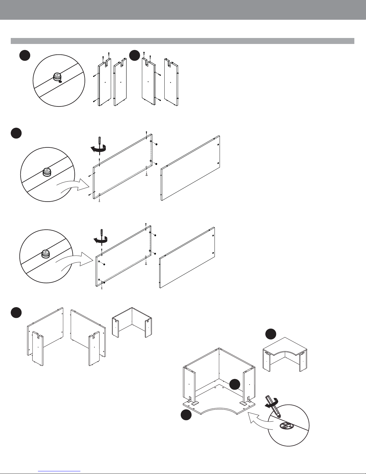
GLOBALContract
INSTALLATION GUIDELINES
3 3a
LEFT HAND APPLICATION RIGHT HAND APPLICATION
3b
• Fall 2017
Corner Desk Inset Back Panel
Corner Desk Full Back Panel
4
6
Page • globalcontract.com49
5
7
Back Panel
Top Underside
Page 51
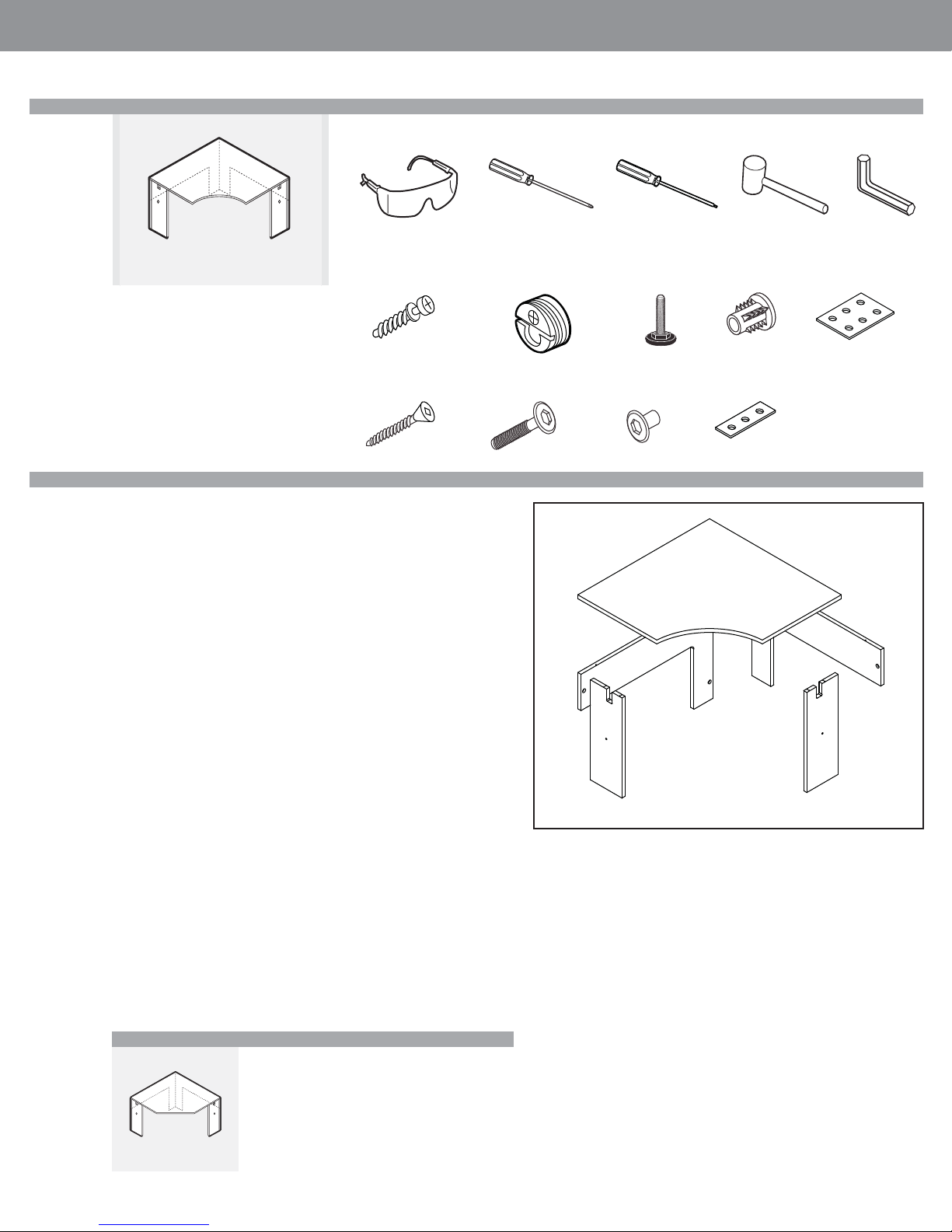
GLOBALContract
L2CCxxxxxx
NOTE: Open and assemble only one product
at a time to avoid a potential mix-up of parts
and hardware.
It is adviseable to assemble the unit on a
carpet to avoid scratches.
• Fall 2017
INSTALLATION GUIDELINES
Required Tools
Safety Glasses Hex Wrench
Included Hardware
Blum Connector
Screw L005650060
Wood Screw #8 3/4
L007250032
Screwdriver #2 Phillips Rubber MalletScrewdriver Roberson
Blum Connector
(installed) L005650061
Connector Bolt
L005650114
Leveler
L007250037
Connector Nut
L005650117
“T” Nut Insert
L007250039
Bracket
L005651035
Flat Bracket
L005650025
Assembly
STEP 1: Unpack and inspect individual pieces for damages or missing hardware
STEP 2: Pick a clean unobstructed area to assemble desk. It is advisable to assembly of this product upright.
STEP 3: Determine position of left and right gables as this will determine position
of hardware.
a. Partial gables, orient so that exposed holes are on the back edge. Install
levellers into T nuts, use mallet to install into pre-drilled holes on the
bottom of gable. Install Blum connector screws on the top and only top
position on back edge into pre-drilled holes. Note that 2 holes are available
in each position, install in hole closest to underside of the desk.
b. Back panel one. Orient with Blum connectors facing inside of desk so
that exposed Blum connectors line up with partial gable. Install levellers
into T nuts, install into pre-drilled holes on bottom of gable using a mallet.
Install Blum connector screws on the top and side edge opposite Blum
connectors, into pre-drilled holes.
STEP 4: Connect chassis together by lining up Blum connectors with Blum connector screws on adjoining pieces. Tighten Blum connectors ¼ turn, do not over
tighten.
STEP 5: Lay worksuface on fl oor with Blum connectors facing up. Install assembled
chassis by lining up Blum connector screws with the Blum connectors on the
worksurface top. Tighten Blum connectors ¼ turn, do not over tighten.
STEP 6: Stand completed assembly upright.
WORKSURFACE
HALF
BACK
HALF BACK
NARROW GABLE
NARROW GABLE
STEP 7: Using the provided #8 x ¾ wood screws, secure fl at brackets to the underside of adjoining surfaces. The half fl at bracket is to be installed in the “cableway”
opening in the partial gable. Install full fl at bracket half way between front edge of
surface and the front edge of the partial Gable.
a. Connecter Bolts and nuts will be used to gang narrow gable to partial
gable of adjoining assembly using hex wrench.
Installation For Similar Products
L2CCHxxxxxx
•Pageglobalcontract.com 50
Page 52
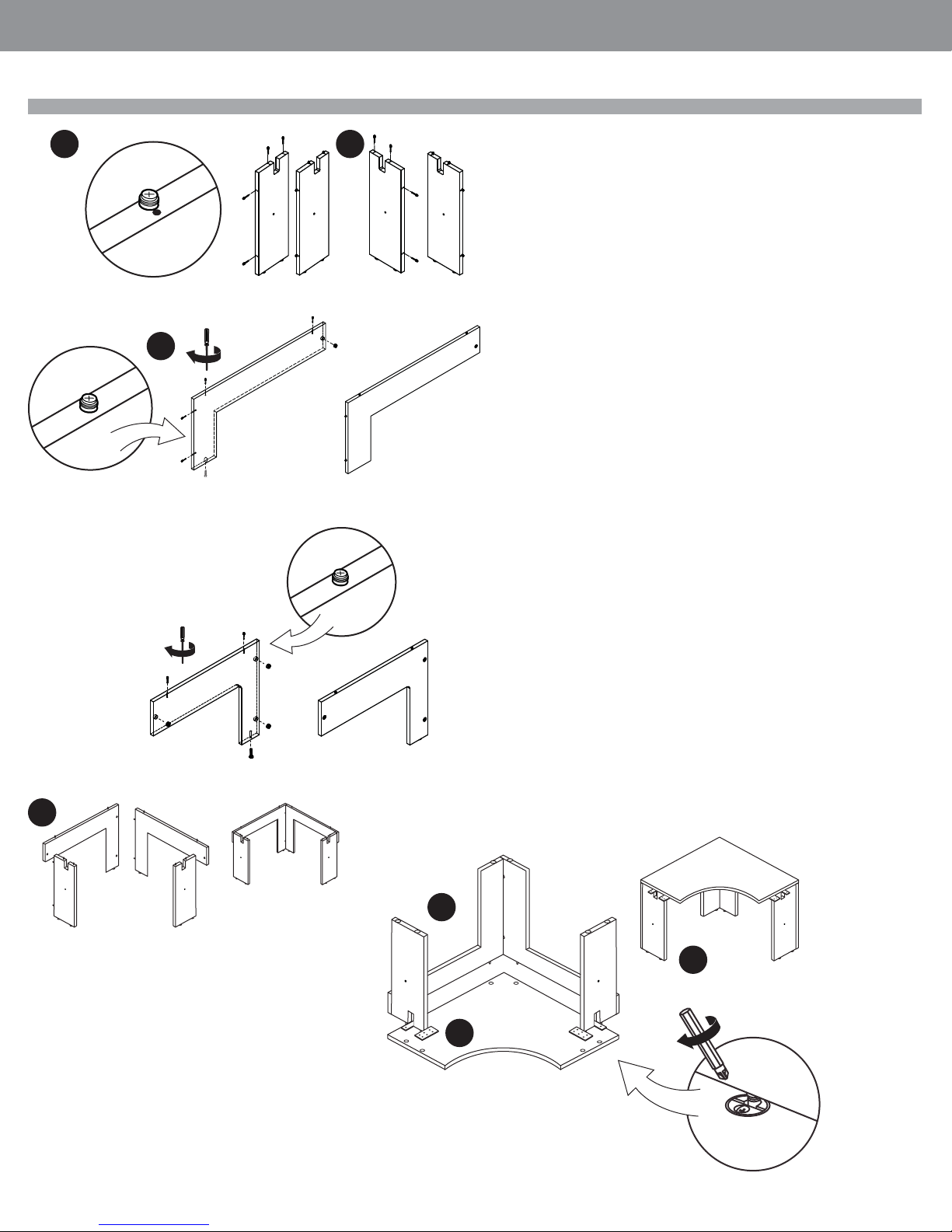
GLOBALContract
INSTALLATION GUIDELINES
3 3a
LEFT HAND APPLICATION RIGHT HAND APPLICATION
3b
• Fall 2017
Corner Desk Cut Back Panel
4
Corner Desk Inset Cut Back Panel
5
Page • globalcontract.com51
6
7
Back Panel
Top Underside
Page 53
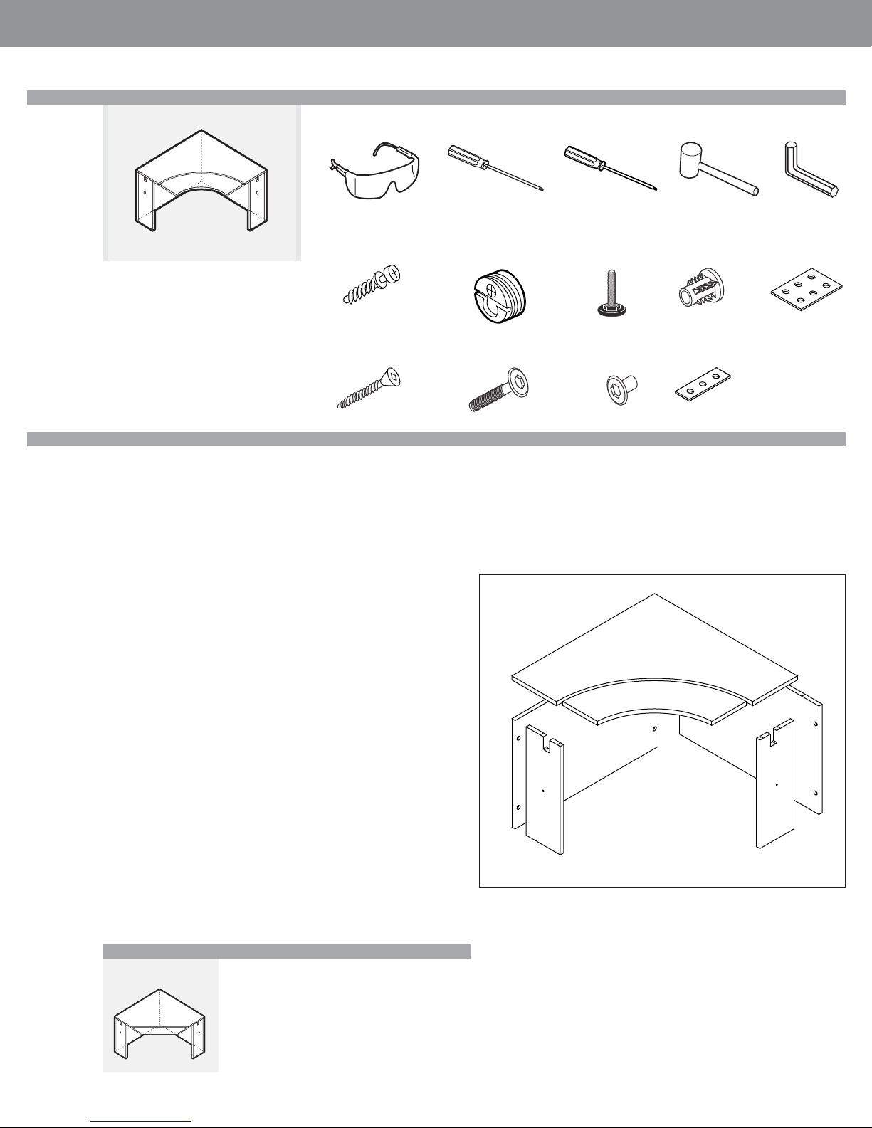
GLOBALContract
L2CK
NOTE: Open and assemble only one product
at a time to avoid a potential mix-up of parts
and hardware.
It is adviseable to assemble the unit on a
carpet to avoid scratches.
• Fall 2017
INSTALLATION GUIDELINES
Required Tools
Safety Glasses Hex Wrench
Included Hardware
Blum Connector
Screw L005650060
Wood Screw #8 3/4
L007250032
Screwdriver #2 Phillips Rubber MalletScrewdriver Roberson
Blum Connector
(installed) L005650061
Connector Bolt
L005650114
Leveler
L007250037
Connector Nut
L005650117
“T” Nut Insert
L007250039
Bracket
L005651035
Flat Bracket
L005650025
Assembly
STEP 1: Unpack and inspect individual pieces for damages or missing hardware.
STEP 2: Pick a clean unobstructed area to assemble desk. This unit is best to assemble upside down.
STEP 3: Determine position of left and right gables as this will determine position
of hardware.
a. Partial gables, orient so that exposed holes are on the back edge. Install
levellers into T nuts, using mallet install into pre-drilled holes on the bottom
of gable. Install Blum connector screws on the top and back edge into pre drilled holes. Note that 2 holes are available in each position, install in hole
closest to underside of the desk.
b. Back panel one. Orient with Blum connectors facing inside of desk so
that exposed Blum connectors line up with partial gable. Install levellers
into T nuts, using mallet install into pre-drilled holes on the bottom of
gable. Install Blum connector screws on the top and side edge opposite
Blum connectors, into pre-drilled holes.
STEP 4: Connect chassis together by lining up Blum connectors with Blum connector screws on adjoining pieces. Tighten Blum connectors ¼ turn, do not over
tighten.
STEP 5: Lay worksuface on fl oor with Blum connectors facing up. Install assembled
chassis by lining up Blum connector screws with the Blum connectors on the
worksurface top. Tighten Blum connectors ¼ turn, do not over tighten.
STEP 6: Lay keyboard tray along front edge of main worksurface, space with 1”
gap between keyboard tray and main surface. Place keyboard mechanism in place,
centering along centerline. Screw into main surface and key board surface using
#8x3/4 wood screws provided.
STEP 7: Stand completed assembly upright.
STEP 8: Using the provided #8 x ¾ wood screws, secure fl at brackets to the underside of adjoining surfaces. The half fl at bracket is to be installed in the “cableway”
opening in the partial gable. Install full fl at bracket half way between front edge of
surface and the front edge of the partial Gable.
a. Connecter bolts and nuts will be used to gang narrow gable to partial
gable of adjoining assembly using hex wrench.
WORKSURFACE
BACK PANEL
BACK PANEL
NARROW GABLE
NARROW GABLE
Installation For Similar Products
L2CSKxxxxxx
•Pageglobalcontract.com 52
Page 54
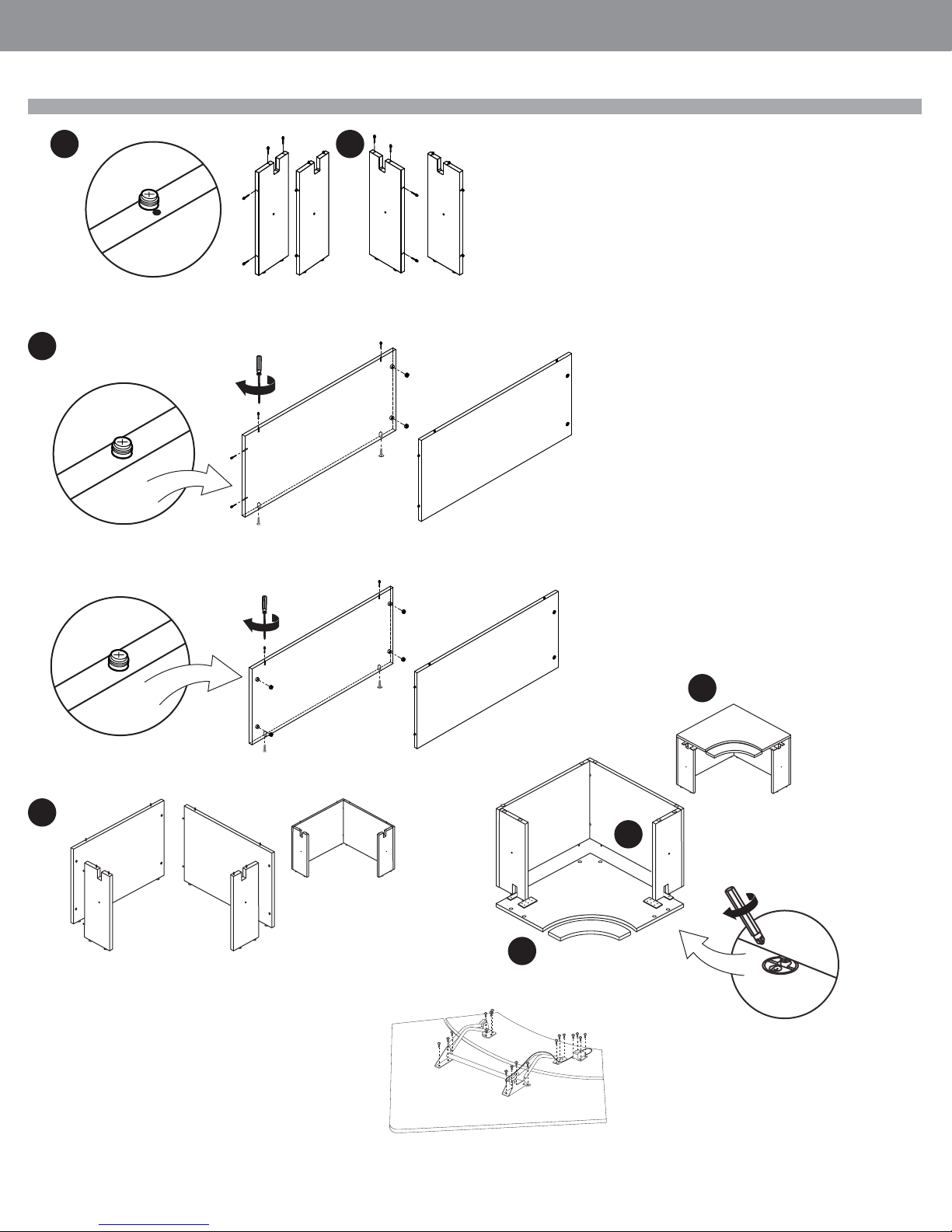
GLOBALContract
INSTALLATION GUIDELINES
3 3a
LEFT HAND APPLICATION RIGHT HAND APPLICATION
3b
• Fall 2017
Corner Desk Inset Back Panel
Corner Desk Full Back Panel
4
6
5
Back Panel
7
Top Underside
Page • globalcontract.com53
Attach and assemble the keyboard mechanism as instructed by the directions included in the packaging.
Page 55
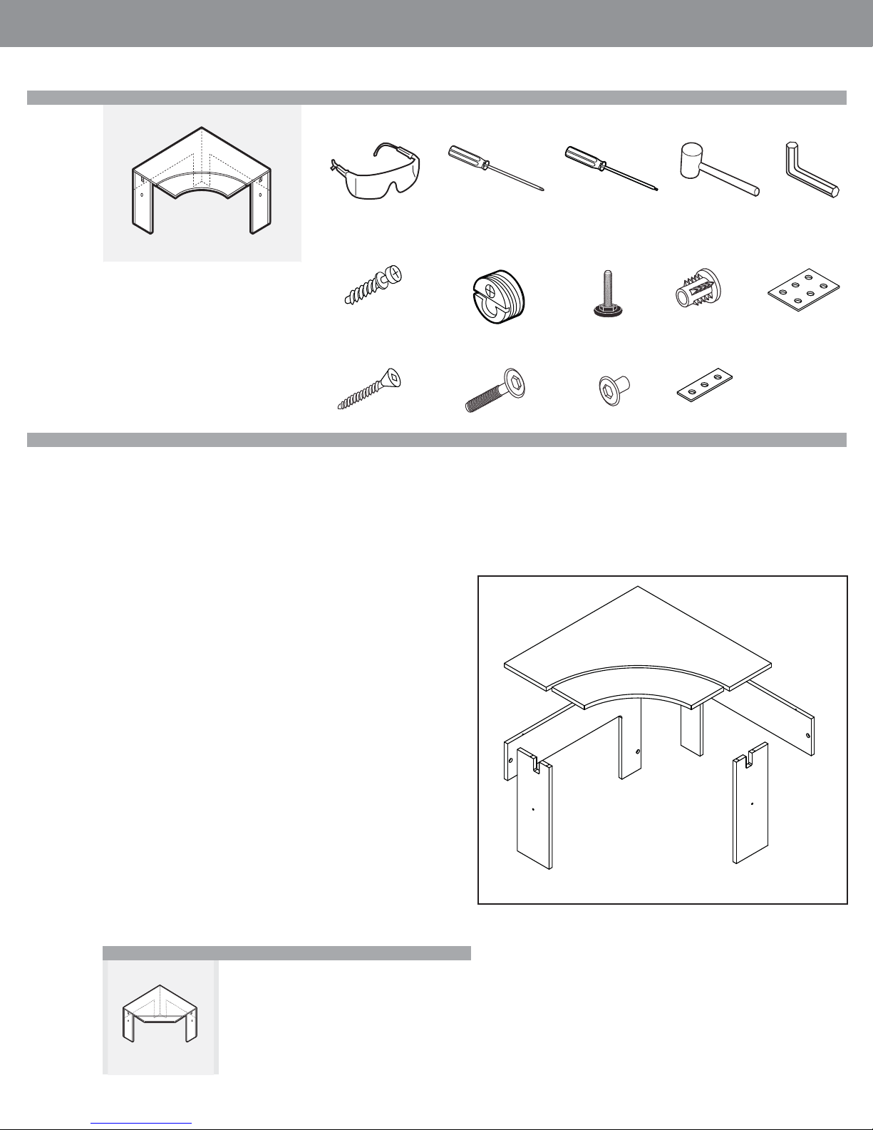
GLOBALContract
L2CHK
NOTE: Open and assemble only one product
at a time to avoid a potential mix-up of parts
and hardware.
It is adviseable to assemble the unit on a
carpet to avoid scratches.
• Fall 2017
INSTALLATION GUIDELINES
Required Tools
Safety Glasses Hex Wrench
Included Hardware
Blum Connector
Screw L005650060
Wood Screw #8 3/4
L007250032
Screwdriver #2 Phillips Rubber MalletScrewdriver Roberson
Blum Connector
(installed) L005650061
Connector Bolt
L005650114
Leveler
L007250037
Connector Nut
L005650117
“T” Nut Insert
L007250039
Bracket
L005651035
Flat Bracket
L005650025
Assembly
STEP 1: Unpack and inspect individual pieces for damages or missing hardware.
STEP 2: Pick a clean unobstructed area to assemble desk. This unit is best to assemble upside down.
STEP 3: Determine position of left and right gables as this will determine position
of hardware.
a. Partial gables, orient so that exposed holes are on the back edge. Install
levellers into T nuts, install into pre-drilled holes on bottom of gable using a
mallet. Install Blum connector screws on the top and only top position on
back edge into pre-drilled holes. Note that 2 holes are available in each
position, install in hole closest to underside of the desk.
b. Back panel one. Orient with Blum connectors facing inside of desk so
that exposed Blum connectors line up with partial gable. Install levellers
into T , install into pre-drilled holes on bottom of gable using a mallet.
Install Blum connector screws on the top and side edge opposite Blum
connectors, into pre-drilled holes.
STEP 4: Connect chassis together by lining up Blum connectors with Blum connector screws on adjoining pieces. Tighten Blum connectors ¼ turn, do not over
tighten.
STEP 5: Lay worksuface on fl oor with Blum connectors facing up. Install assembled
chassis by lining up Blum connector screws with the Blum connectors on the
worksurface top. Tighten Blum connectors ¼ turn, do not over tighten.
STEP 6: Lay keyboard tray along front edge of main worksurface, space with 1”
gap between keyboard tray and main surface. Place keyboard mechanism in place,
centering along centerline. Screw into main surface and key board surface using
#8x3/4 wood screws provided.
STEP 7: Stand completed assembly upright.
STEP 8: Using the provided #8 x ¾ wood screws, secure fl at brackets to the underside of adjoining surfaces. The half fl at bracket is to be installed in the “cableway”
opening in the partial gable. Install full fl at bracket half way between front edge of
surface and the front edge of the partial Gable.
a. Connecter bolts and nuts will be used to gang partial gable to partial
gable of adjoining assembly using hex wrench.
WORKSURFACE
HALF BACK
HALF BACK
NARROW GABLE
NARROW GABLE
Installation For Similar Products
L2CSHKxxxxxx
•Pageglobalcontract.com 54
Page 56
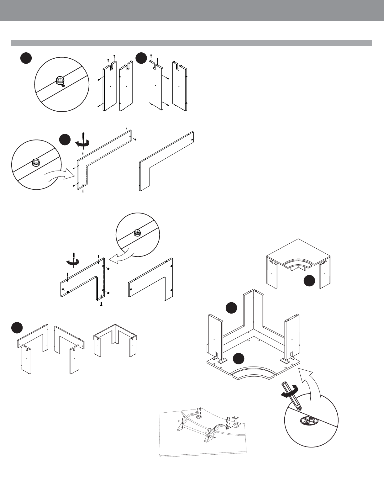
GLOBALContract
INSTALLATION GUIDELINES
3 3a
LEFT HAND APPLICATION RIGHT HAND APPLICATION
3b
• Fall 2017
Corner Desk Cut Back Panel
4
Corner Desk Inset Cut Back Panel
6
5
7
Page • globalcontract.com55
Back Panel
Top Underside
Attach and assemble the keyboard mechanism as instructed by the directions included in the packaging.
Page 57
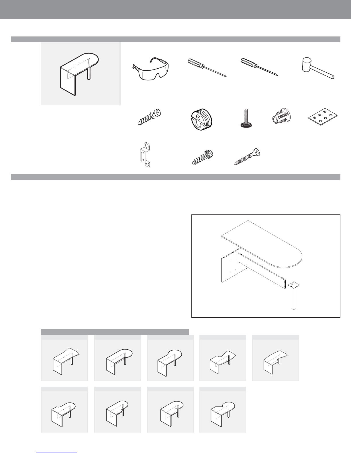
GLOBALContract
L2TDHxxxxxx
NOTE: Open and assemble only one product
at a time to avoid a potential mix-up of parts
and hardware.
INSTALLATION GUIDELINES
Required Tools
Safety Glasses Rubber MalletScrewdriver #2 Phillips Screwdriver #2 Robertson
Included Hardware
Blum Connector
Screw L005650060
Blum Connector
(installed) L005650061
Leveler
L007250037
“T” Nut Insert
L007250039
• Fall 2017
Flat Bracket
L005650025
It is adviseable to assemble the unit on a
carpet to avoid scratches. Modular Screw
Modular Connector
(installed) L004250001
L007250001
Assembly
STEP 1: Unpack and inspect individual pieces for damages or missing hardware.
STEP 2: Pick a clean unobstructed area to assemble desk. This unit is best to assemble upside down.
STEP 3: Orient Gable with Pre-drilled Holes facing underside of the desk assembly.
a. Install levellers into T Nut inserts on the bottom of the gable.
b. Install Blum Connector screws into pre-drilled holes on the top edge of
the gable.
c. Based on the application, see drawing for positioning, install Modular
connector screws in the top two pre-drilled hole positions.
STEP 4: Half modesty. The half modesty will have modular connectors pre-installed
on each end.
a. Connect half modesty to the full gable by lining up modular connectors
with modular screws and slide half gable down, you can use a mallet to
securely seat the half gable into position.
b. Install 2 shoulder screws into pre-drilled holes on the side on the monoleg.
Connect half modesty to the monoleg by lining up modular connectors with
modular screws and slide half modesty down, you can use a mallet to
securely seat the half gable into position.
c. Screw monoleg to the worksurface using #8x3/4 wood screws provided
STEP 5: Turn Assembly upright.
STEP 6: This product is intended to be ganged to adjoin surface. Using fl at
brackets, secure with #8x3/4 wood screws to attach underside of surface to join
assemblies.
Wood Screw #8 3/4
L007250032
WORKSURFACE
GABLE
HALF MODESTY
MONOLEG
L2BHML03 (default)
or
L2LSQ3X3
Installation For Similar Products
L2TAHxxxx
L2TEDHxxxxxxL
L2TPHxxxxL
L2TEDHxxxxxxR
L2TPHxxxxR
L2TEDHCOxxxxxxR
L2THHxxxxxxL
L2TEDHCOxxxxxxL
L2THHxxxxxxR
•Pageglobalcontract.com 56
Page 58
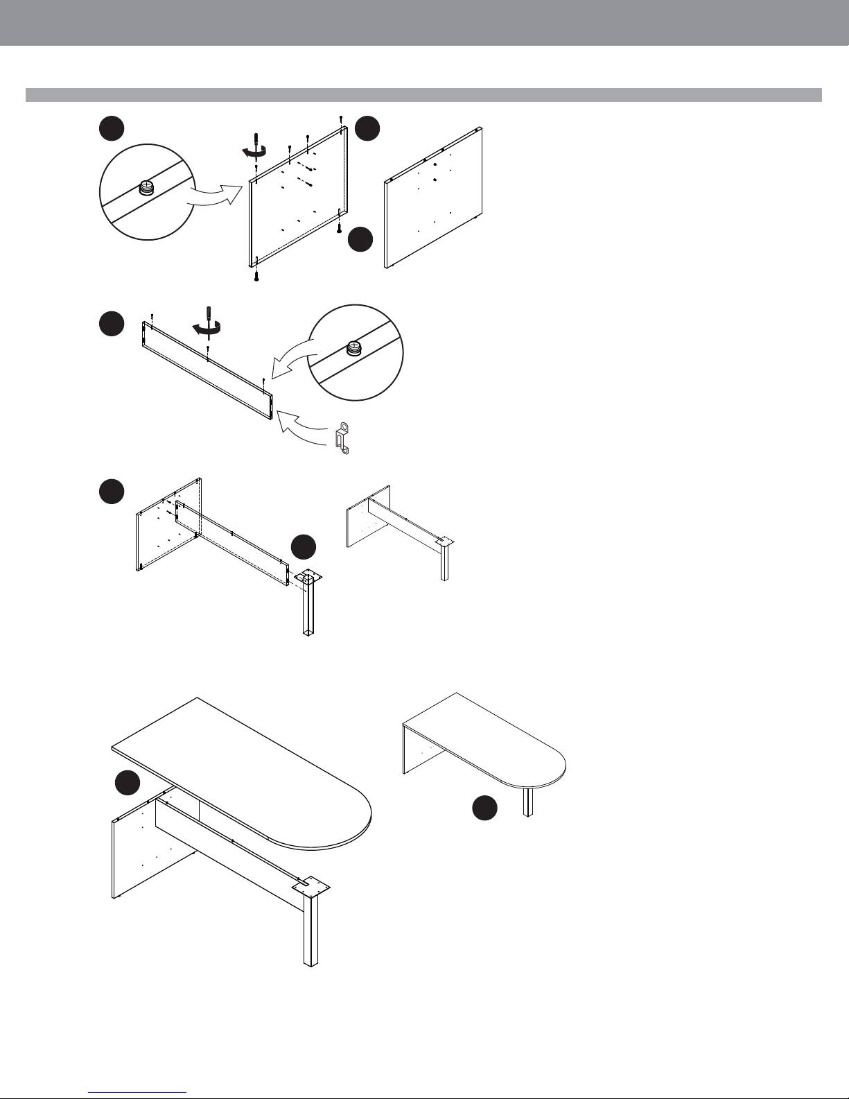
GLOBALContract
INSTALLATION GUIDELINES
3 3b
3a
4
• Fall 2017
4a
4b
4c
5
Page • globalcontract.com57
Page 59
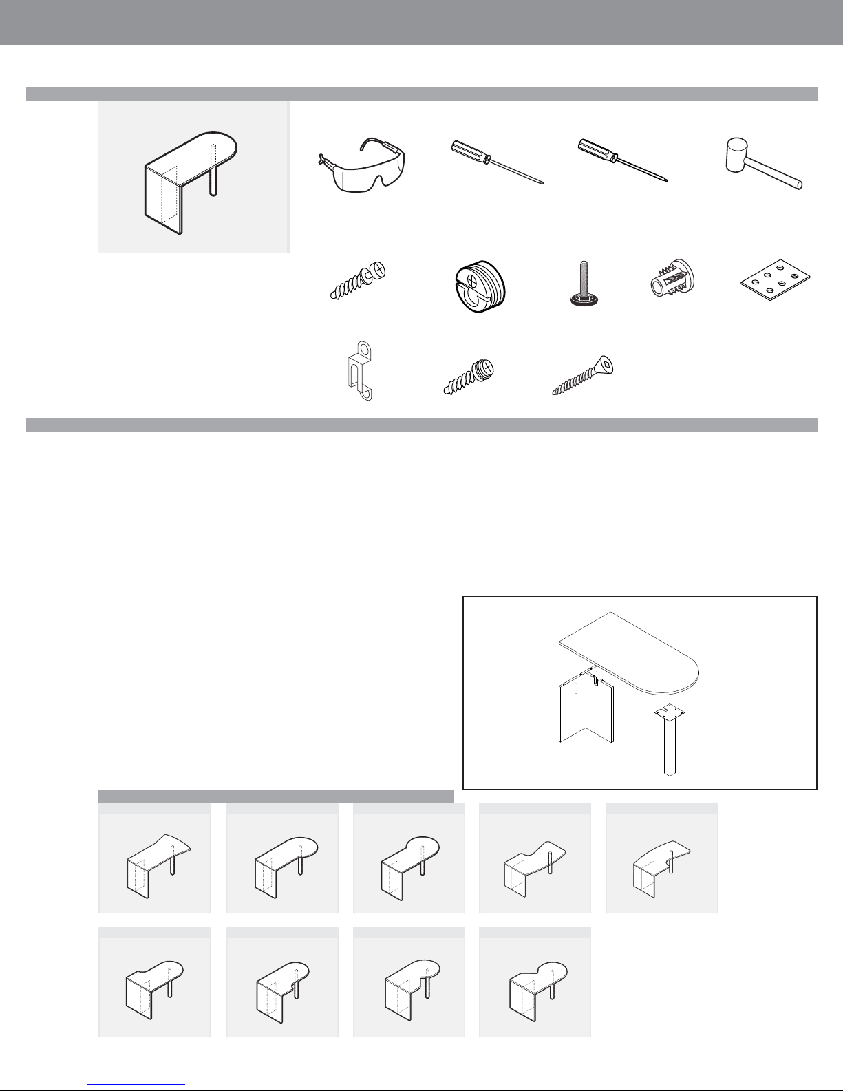
GLOBALContract
L2TDxxxxxx
NOTE: Open and assemble only one product
at a time to avoid a potential mix-up of parts
and hardware.
INSTALLATION GUIDELINES
Required Tools
Safety Glasses Rubber MalletScrewdriver #2 Phillips Screwdriver #2 Robertson
Included Hardware
Blum Connector
Screw L005650060
Blum Connector
(installed) L005650061
Leveler
L007250037
“T” Nut Insert
L007250039
• Fall 2017
Flat Bracket
L005650025
It is adviseable to assemble the unit on a
carpet to avoid scratches. Modular Screw
Modular Connector
(installed) L004250001 Wood Screw #8 3/4
L007250001
Assembly
STEP 1: Unpack and inspect individual pieces for damages or missing hardware.
STEP 2: Pick a clean unobstructed area to assemble desk. This unit is best to assemble upside down.
STEP 3: Orient gable with pre-drilled Holes facing underside of the desk assembly.
a. Install levellers into T nuts, using mallet install into pre-drilled holes on
the bottom of gable.
b. Install Blum Connector screws into pre-drilled holes on the top edge of
the gable.
c. Based on the application, see drawing for positioning, install Modular
connector screws in the top and bottom pre-drilled hole positions.
STEP 4: Partial Gable Install levellers into T nuts, using mallet install into pre-drilled
holes on the bottom of gable. The half gable will have modular connectors preinstalled on back edge.
STEP 5: Connect partial gable to the full gable by lining up modular connectors with
modular screws and slide half gable down, you can use a mallet to securely seat the
half gable into position.
STEP 6: Lay worksurface face down on clean surface, be sure to verify handedness.
Connect chassis by ling up Blum connector screws on the gables with Blum con-
nectors on the bottom of the surface. Turn the screw on Blum Connector ¼ turn, do
not over tighten.
STEP 7: Install Monoleg, No pre-drilled holes are provided. Place monoleg along
center line, lining up with half gable, leaving equal distance from the end and the
sides. Screw into place with provided # 8 x ¾ wood screws.
STEP 8: Turn Assembly upright.
STEP 9: This product is intended to be ganged to adjoin surface. Using fl at brackets,
secure with #8x3/4 wood screws to attach underside of surface to adjoin assembly.
END GABLE
L007250032
NARROW GABLE
WORKSURFACE
MONOLEG
L2BHML03 (default)
or
L2LSQ3X3
Installation For Similar Products
L2TAxxxx
L2TEDxxxxxxL
L2TPxxxxL
L2TEDxxxxxxR
L2TPxxxxR
L2TEDCOxxxxxxR
L2THxxxxxxL
L2TEDCOxxxxxxL
L2THxxxxxxR
•Pageglobalcontract.com 58
Page 60
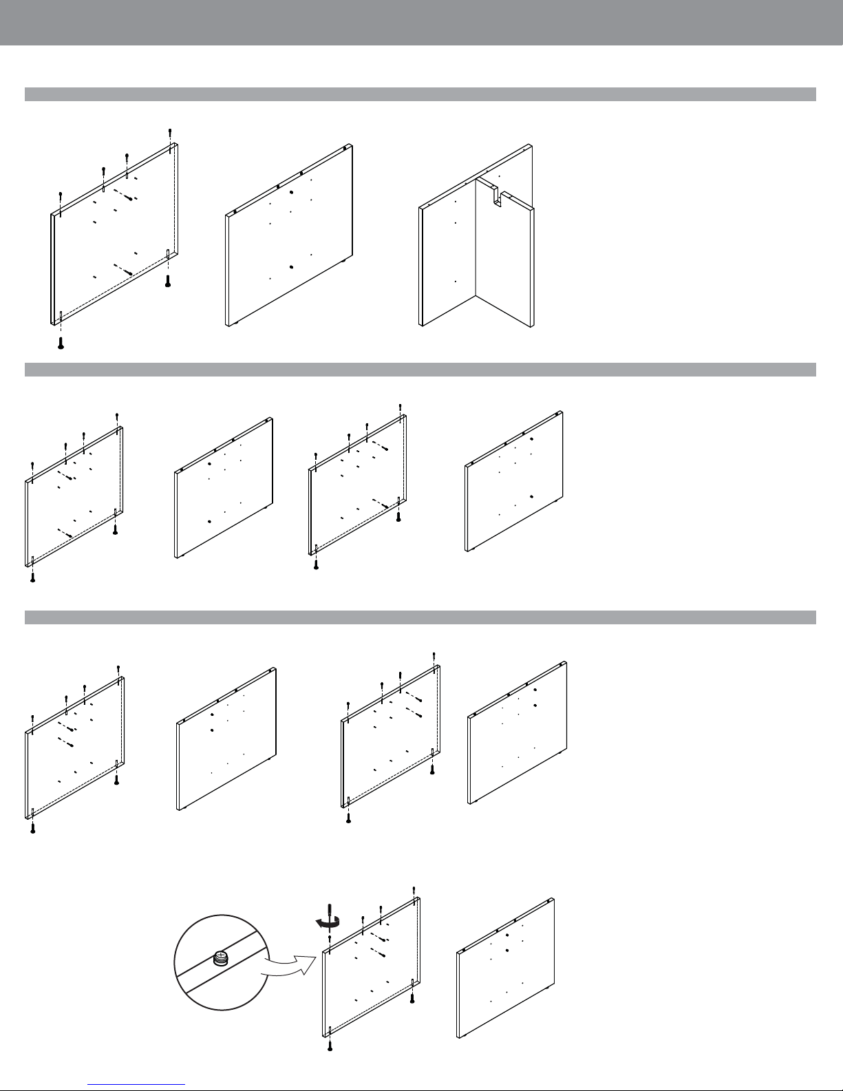
GLOBALContract
INSTALLATION GUIDELINES
End Panel for T-Base Aplications (D Table, P Table, and Axe Table)
T Base End Panel for Hockey Shaped Tables Aplication
• Fall 2017
LEFT APPLICATION
End Panel for Modesty Aplications Hockey Shaped Tables
LEFT APPLICATION
RIGHT APPLICATION
RIGHT APPLICATION
Page • globalcontract.com59
Page 61
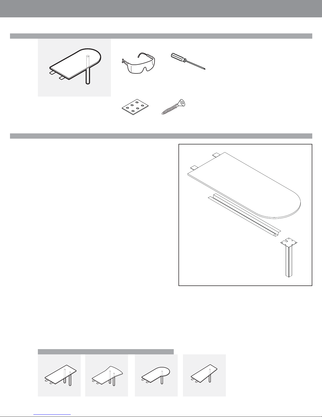
GLOBALContract
L2TCDxxxxxx
NOTE: Open and assemble only one product
at a time to avoid a potential mix-up of parts
and hardware.
It is adviseable to assemble the unit on a
carpet to avoid scratches.
Assembly
STEP 1: Unpack and inspect individual pieces for damages or missing hardware.
STEP 2: Pick a clean unobstructed area to assemble desk. This unit is best to assemble upside down.
INSTALLATION GUIDELINES
Required Tools
Safety Glasses Screwdriver #2 Robertson
Included Hardware
Flat Bracket
L005650025
Wood Screw #8 3/4
L007250032
• Fall 2017
STEP 3: Place worksurface face down on clean unobstructed area.
STEP 4: Place monoleg(s) as per product evenly spaced leaving overhang based on
shape of worksurface top. Using #8x 3/4 wood screws to secure to the bottom of
the surface.
STEP 5: This product is shipped with “HAT” channel support bar, install along the
bottom of the surface.
Note: Please allow room to install a keyboard tray at the users edge if needed.
STEP 6: This product is intended to gang to existing assembly. Using fl at brackets,
install with #8x 3/4 wood screws.
WORKSURFACE
HAT CHANNEL
MONOLEG
BHML03 (default)
or
LLSQ3X3H28
Installation For Similar Products
L2TCRxxxx L2TCAxxxxL L2TCPxxxxR L2TCWxxxxxxL/R
Left Hand Shown
•Pageglobalcontract.com 60
Page 62
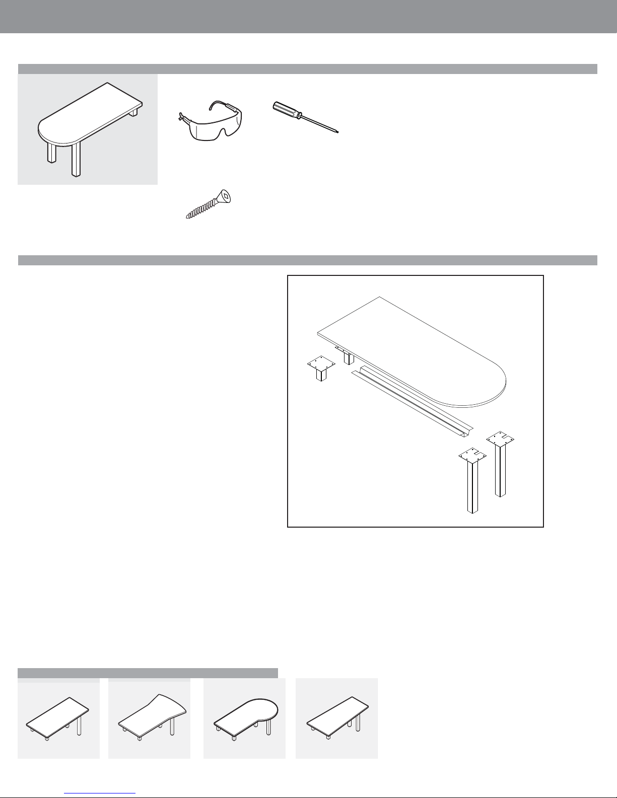
GLOBALContract
INSTALLATION GUIDELINES
L2FDxxxxxx
Required Tools
Safety Glasses Screwdriver #2 Robertson
Included Hardware
Wood Screw #8 3/4
L007250032
NOTE: Open and assemble only one product
at a time to avoid a potential mix-up of parts
and hardware.
It is adviseable to assemble the unit on a
carpet to avoid scratches.
Assembly
STEP 1: Unpack and inspect individual pieces for damages or missing hardware.
STEP 2: Pick a clean unobstructed area to assemble desk. This unit is best to assemble upside down.
• Fall 2017
STEP 3: Place worksurface face down on clean unobstructed work area.
STEP 4: Place full monolegs as per product evenly spaced leaving overhang based
on shape of worksurface top and 4 “ from front and back edge. Secure using
#8x3/4 wood screws to secure to the bottom of the surface.
STEP 5: Place small monolegs at straight end. These legs should be placed 4”
from both back and side edges. Secure using #8x3/4 wood screws to secure to the
bottom of the surface. The short legs are shipped with a 5/16 bolt installed into the
bottom.
STEP 6: This product is shipped with a “HAT” channel support bar, install along
bottom of the surface. Please note that allow room to install Keyboard tray at users
edge if needed.
STEP 7: This product is intended to support from and be ganged to Licence 1 high
storage. To connect the small legs to Licence storage, Drill 3/8” through hole in
base storage and use bolt from inside storage to line up with nutsert in bottom of
the short leg.
WORKSURFACE
LLSQ3X3
HAT CHANNEL
MONOLEGS
LLSQ3X3H28
Installation For Similar Products
L2FRxxxx L2FAxxxxL L2FPxxxxR L2TCWxxxxL/R
Left Hand Shown
Page • globalcontract.com61
Page 63
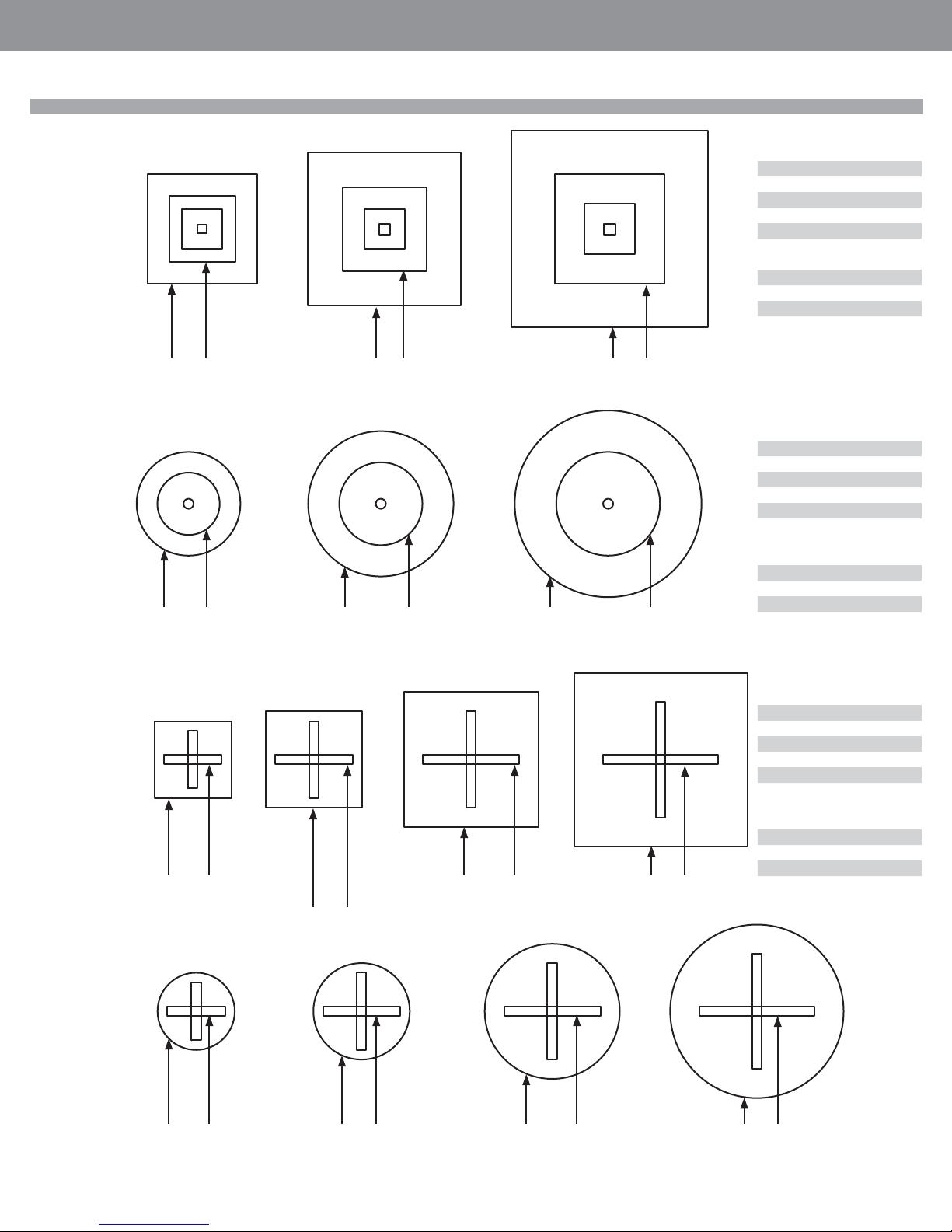
GLOBALContract
Table Dimension Chart
• Fall 2017
INSTALLATION GUIDELINES
TTSQ - Flat Square Column Base
36”x36” Top
30”x30”
TTFD - Flat Disk
34” DIA Top
18” Base
18” Base
48”x48” Top
42”x42” Top
36” DIA Top30”DIA Top
23” Base
24” Base
48”x48” Top
48” DIA Top
54” DIA Top
30” Base
30” Base
36” Base
FLAT SQUARE
BASE SPREAD TOP SIZE
18” 24x24
18” 30x30
23” 36x36
23” 42x42
30” 48x48
FLAT SQUARE 40.5H
BASE SPREAD TOP SIZE
18” 24x24
23” 30x30
30” 36x36
FLAT DISC 28H
BASE SPREAD TOP SIZE
18” 24x24
18” 30x30
24” 36x36
30” 42x42
30” 48x48
36” 54x54
FLAT DISC 40.5H
BASE SPREAD TOP SIZE
18” 24x24
22” 30x30
24” 36x36
TTFLTX - FLAT BAR “X” Column Base
30”x30” Top
24”DIA Top
30”DIA Top
18” Base
42”x42” Top
30”x30”
18” Base
36”DIA Top
30”DIA
24” Base
24” Base
48”x48” Top
42”x42” Top
30” Base
48”DIA Top
42”DIA Top
30” Base
54”x54” Top
36” Base
54”DIA Top
FLATBAR X
BASE SPREAD TOP SIZE
18” 24x24
18” 30x30
24” 36x36
24” 42x42
30” 48x48
36” 54x54
FLATBAR X 40.5H
BASE SPREAD TOP SIZE
18” 24x24
24” 30x30
30” 36x36
36” Base
•Pageglobalcontract.com 62
Page 64
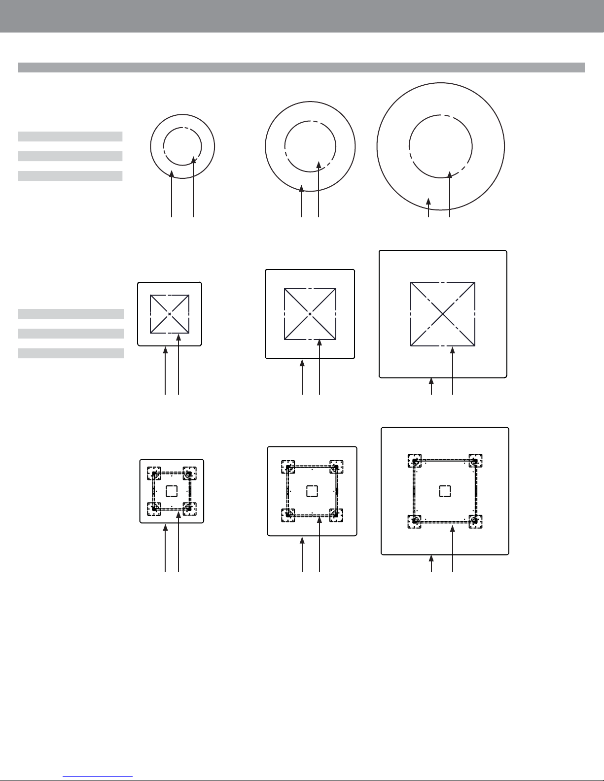
GLOBALContract
INSTALLATION GUIDELINES
Table Dimension Chart
LDRUM - Drum Base
TD DRUM
BASE SPREAD ROUND TOP SIZE
18” dia 30” dia
18” dia 36” dia
24” dia 42” dia
24” dia 48” dia
30” dia 54” dia
30” dia 60” dia
• Fall 2017
LSQ - Square Base
LR, LSQ, TELRS, TELRR, TELBS,
TELBR
BASE SPREAD TOP WIDTH
18” 30
18” 36
24” 42
24” 48
30” 54
30” 60
TELRS or TELBS - Square Base
36”xDIA Top
30”xDIA
36”x36” Top
30”x30”
18” Base
LSQ 18” Base
48”DIA Top
42”xDIA Top
48”x48” Top
42”x42” Top
24” Base
LSQ 24” Base
60”xDIA Top
54”xDIA Top
60”x60” Top
54”x54” Top
30” Base
LSQ 30” Base
36”x36” Top
30”x30”
18”x18” Base
Page • globalcontract.com63
48”x48” Top
42”x42” Top
23”x23” Base
60”x60” Top
54”x54” Top
30”x30” Base
Page 65
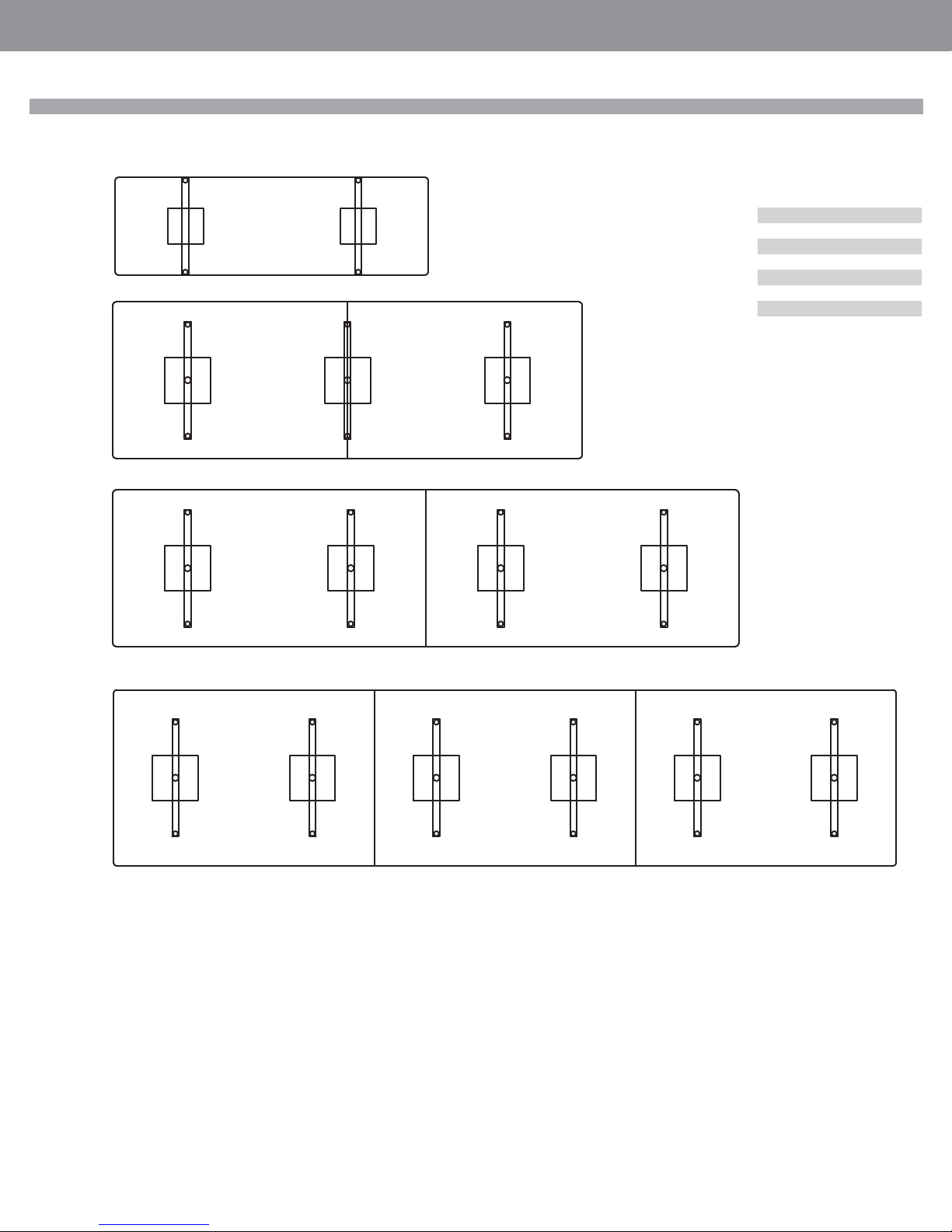
GLOBALContract
Table Dimension Chart
LLTT -”TT” Table Leg with Bulletnose End
LLT - “T” Table Leg with Bulletnose End
• Fall 2017
INSTALLATION GUIDELINES
Tables up 96” Length
Require 2 Bases
Tables 108” to 144” Length
Require 3 T Bases
LLT/LLTT W/BULLNOSE ENDS
BASE SPREAD TOP WIDTH
18” 24W
26” 30W
26” 36W
30” 42W
36” 48W
LLTT only
36” 54W
42” 60W
Tables 156” to 192” Length
Require 4 T Bases
Tables 216” to 240” Length Require 6 T Bases (Tables Larger Than 192” are manufactured in 3 Pieces)
•Pageglobalcontract.com 64
Page 66
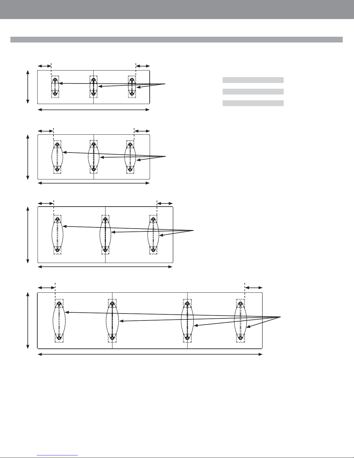
GLOBALContract
INSTALLATION GUIDELINES
Table Dimension Chart
LELBA or LELB - Eliptical Base
• Fall 2017
36”
42” - 48”
54” - 60”
Min 15”
Min 15”
Min 15”
108” - 120”
108” - 192”
Min 15”
Min 15”
Min 15”
18” Elliptical Base
24” Elliptical Base
36” Elliptical Base
LELBA, LELB
BASE SPREAD TOP WIDTH
18” 30
18” 36
24” 42
30” 48
36” 54
36” 60
54” - 60”
Min 15”
144” - 192”
Min 15”
36” Elliptical Base
216” - 240”
Page • globalcontract.com65
Page 67
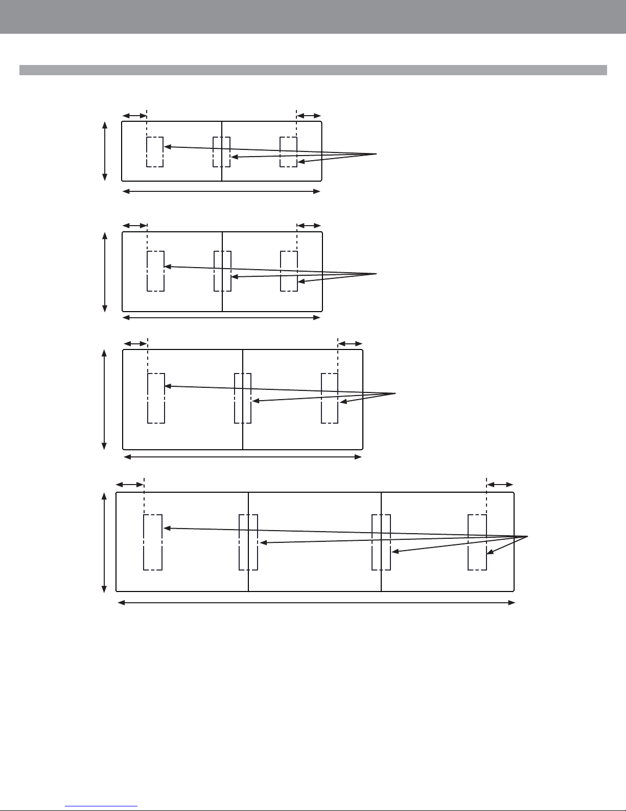
GLOBALContract
Table Dimension Chart
LR - Rectangular Base
• Fall 2017
INSTALLATION GUIDELINES
30” - 36”
42” - 48”
54” - 60”
Min 15”
Min 15”
Min 15”
Min 15”
18” Rectangle Base
108” - 120”
Min 15”
24” Rectangle Base
108” - 192”
Min 15”
36” Rectangular Base
54” - 60”
Min 15”
144” - 192”
Min 15”
30” Rectangular Base
216” - 240”
•Pageglobalcontract.com 66
Page 68
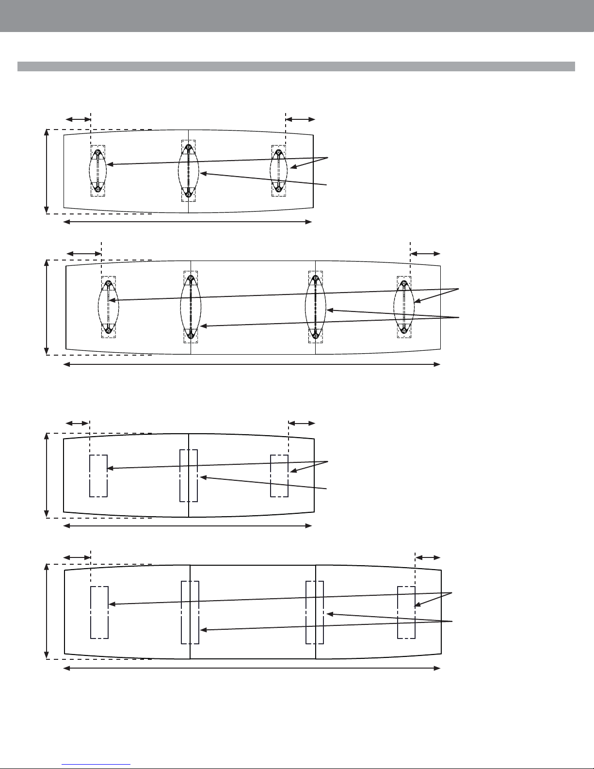
GLOBALContract
INSTALLATION GUIDELINES
Table Dimension Chart
LELBA or LELB - Elliptical Base
• Fall 2017
42” - 48”
54” - 60”
LR - Rectangular Base
Min 15”
Min 15”
Min 15”
24” Elliptical Base
30” Elliptical Base
108” - 192”
Min 15”
30” Elliptical Base
36” Elliptical Base
216” - 240”
42” - 48”
54” - 60”
Min 15”
Min 15”
Min 15”
24” Rectangular Base
30” Rectangular Base
108” - 192”
Min 15”
30” Rectangular Base
36” Rectangular Base
216” - 240”
Page • globalcontract.com67
Page 69
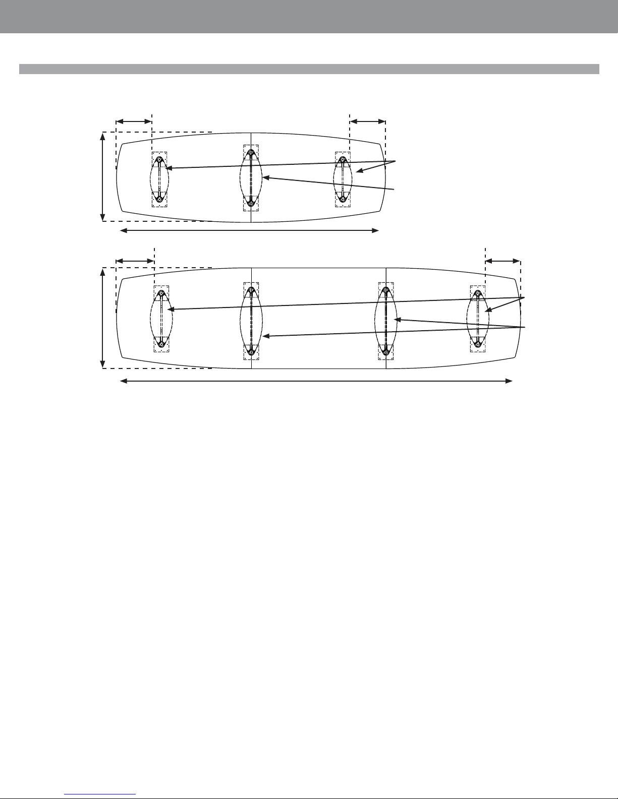
GLOBALContract
Table Dimension Chart
LELBA or LELB - Elliptical Base
• Fall 2017
INSTALLATION GUIDELINES
42” - 48”
54” - 60”
Min 18”
Min 18”
Min 18”
24” Elliptical Base
30” Elliptical Base
108” - 192”
Min 18”
30” Elliptical Base
36” Elliptical Base
216” - 240”
•Pageglobalcontract.com 68
Page 70
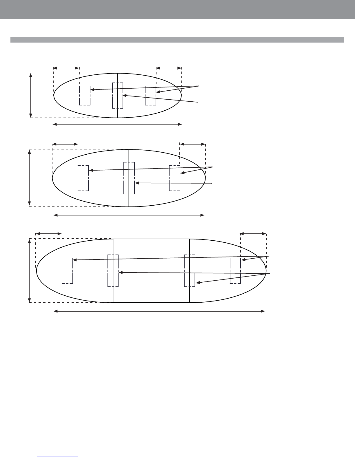
GLOBALContract
INSTALLATION GUIDELINES
Table Dimension Chart
LR - Rectangular Base
• Fall 2017
42” - 48”
54” - 60”
Min 24”
Min 24”
Min 24”
Min 24”
18” Rectangular Base
24” Rectangular Base
108” - 192”
Min 24”
24” Rectangular Base
30” Rectangular Base
144” - 192”
Min 24”
54” - 60”
24” Rectangular Base
30” Rectangular Base
216” - 244”
Page • globalcontract.com69
Page 71
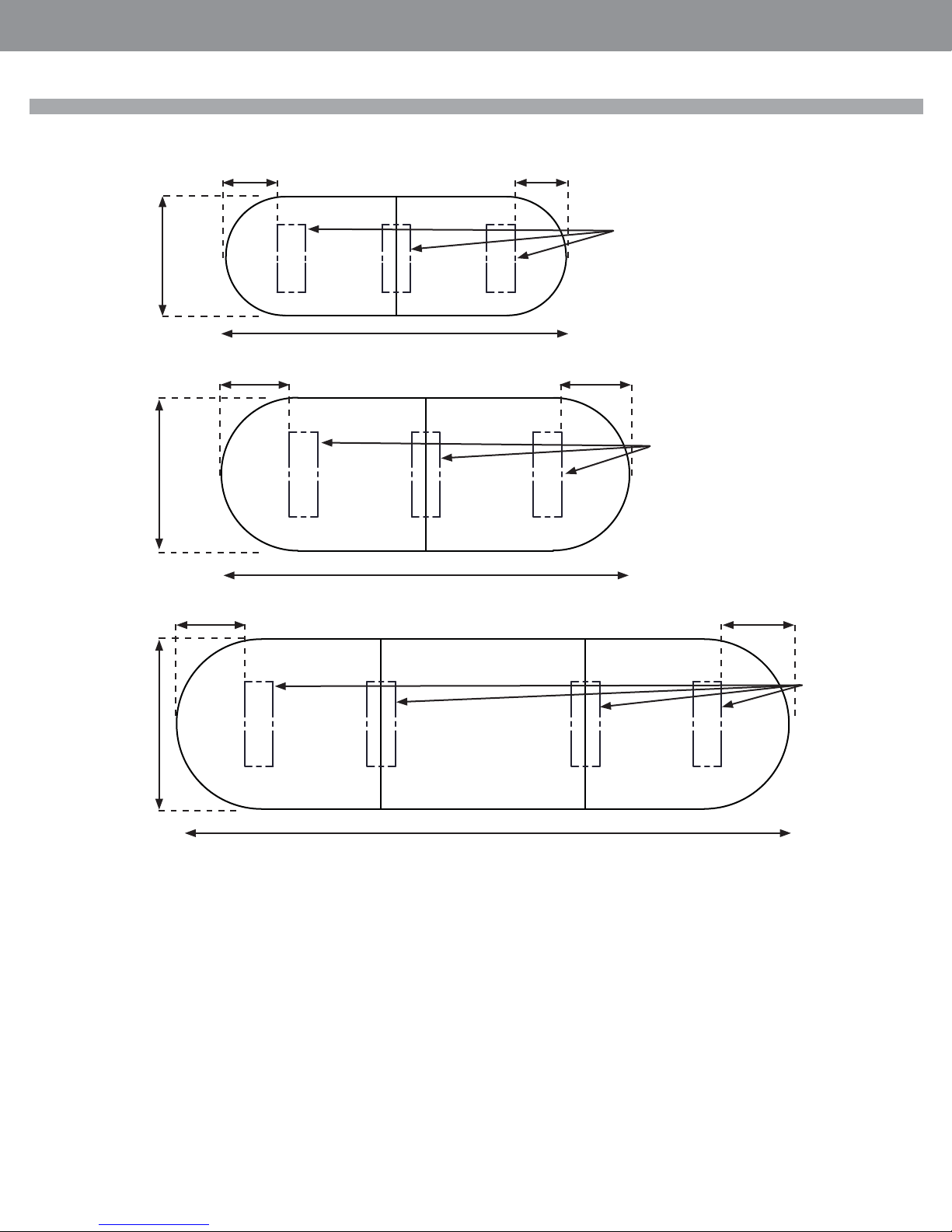
GLOBALContract
Table Dimension Chart
LR - Rectangular Base
• Fall 2017
INSTALLATION GUIDELINES
42” - 48”
54” - 60”
Min 24”
Min 18”
Min 24”
Min 18”
24” Rectangular Base
108” - 192”
Min 24”
30” Rectangular Base
144” - 192”
Min 24”
42” - 48”
30” Rectangular Base
216” 240”
•Pageglobalcontract.com 70
Page 72
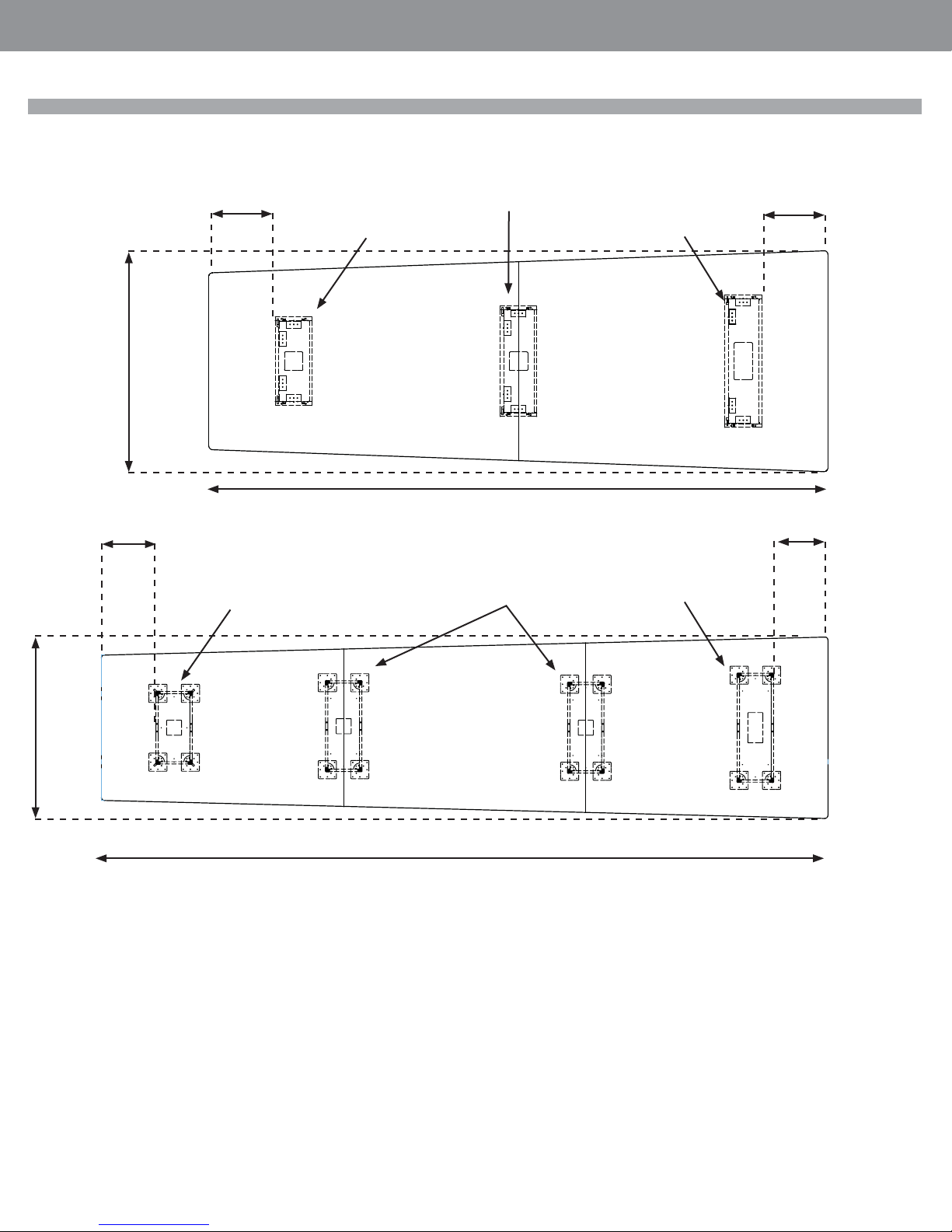
GLOBALContract
INSTALLATION GUIDELINES
Table Dimension Chart
Wedge Table - Rectangular Base
• Fall 2017
LR Base
TELRR or TELLRS Base
60”
168”
Min 24”
24” Rectangular Base
Min 18”
24” Rectangular Base
30” Rectangular Base
30” Rectangular Base
36” Rectangular Base
Min 18”
Min 24”
36” Rectangular Base
60”
240”
Page • globalcontract.com71
Page 73
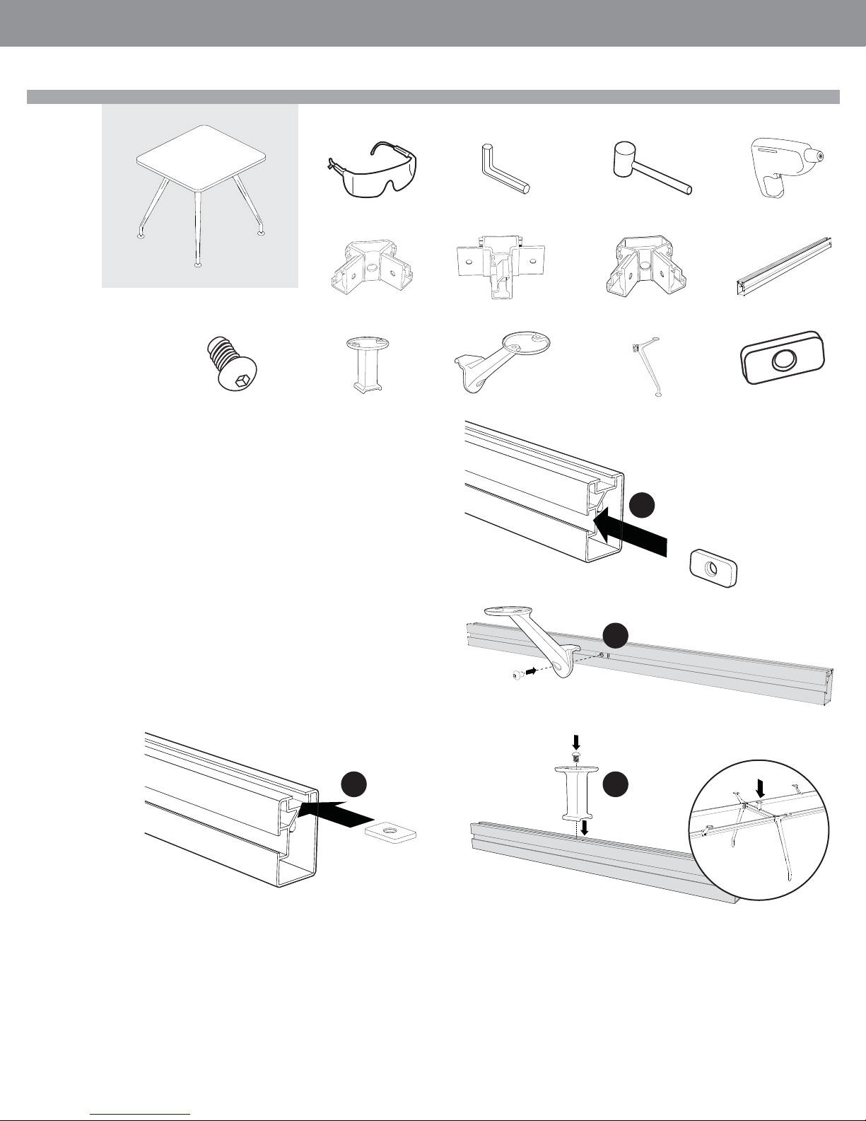
GLOBALContract
Kadin Tables
Note: First assemble the depth, then assemble the width of the table.
INSTALLATION GUIDELINES
Required Tools
Safety Glasses Rubber Mallet Drill
Included Hardware
2 Way Connector 3 Way Connector 2 Way Connector 60 Degree Beam
Plastic Support1/4 -20- 0.5 Screw Diecast Support Leg Slider
Allenkey 3/16”
• Fall 2017
Start at one end of the table and work your way through to the other end
STEP 1: Insert the slider into the groove. Align the slider’s hole with the diecast
support’s hole (Or plastic support’s Hole) and secure them together with the
provided screw.
STEP 1b:Plastic supports are to be used at the seams between two adjoining
table tops.
STEP 2: Attach the legs to either side of the beam with the provided screws.
STEP 3: Once one side is complete, attach the remaining beams to the
assembly and add the provided diecast supports (tables up to 48” will not
include diecast supports).
STEP 4: Each top will include metal inserts - connect the legs and supports to
the top with the provided machine screws.
1
1
1b1b
•Pageglobalcontract.com 72
Page 74
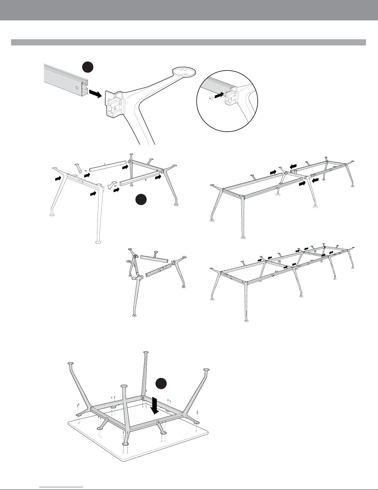
GLOBALContract
INSTALLATION GUIDELINES
Kadin Table
2
1 Piece top
• Fall 2017
2 Piece top
3
3 Piece topRound top
Page • globalcontract.com73
4
Page 75
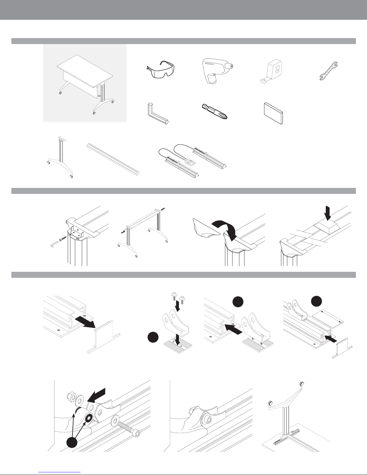
GLOBALContract
Flip Top Tables
Pre Assembled Components
Legs Cable Release/Support BeamsCross Beam
INSTALLATION GUIDELINES
Required Tools
Safety Glasses
Allenkeys Phillips Bit Spacer Block
Drill Measuring Tape Wrench
• Fall 2017
3 9/16” x 1 7/8” (included)
Legs
1. Connect the leg to cross beam.
Pivot Bracket
4. Remove end cap from the end
of the support beam.
2. Snap on black plastic cover to
conceal connection.
5. Ensure pivot bracket is installed 3 9/16” from the end of the extrusion. Replace the end cap.
B
3. Snap support block into channel
on top of cross beam.
C
A
9/16”
3
6. Connect the base to the support beam.
Insure that black nylon washers (A) are installed between the pivot bracket and the assembly.
A
•Pageglobalcontract.com 74
Page 76
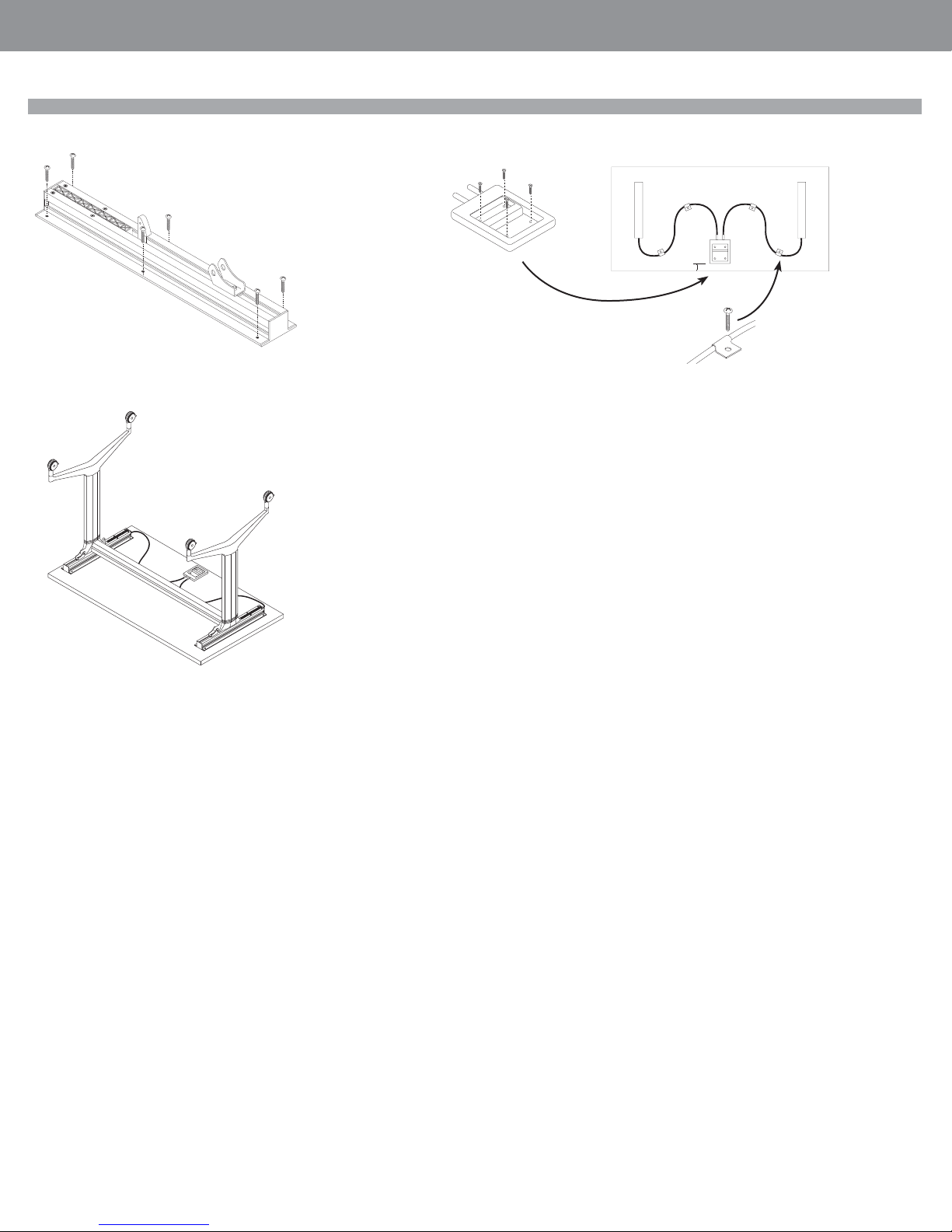
GLOBALContract
INSTALLATION GUIDELINES
Flip top table top
7. Connect the beams to the table top using the pilot
holes provided.
9. Secure the cables to underside of the top with the provided brackets (4).
8. Position cable release mechanism in the center of the table 1” from the user edge
and screw into the underside of the top.
• Fall 2017
1”
Page • globalcontract.com75
Page 77
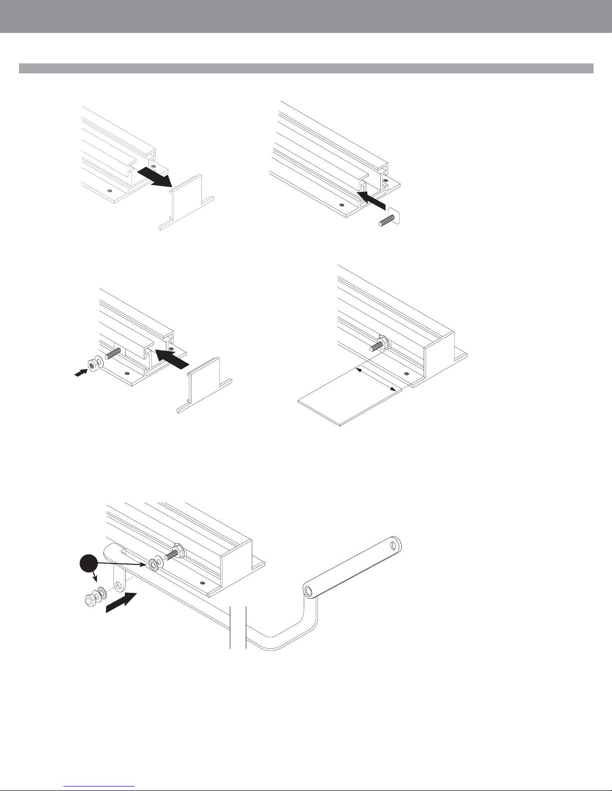
GLOBALContract
Optional Modesty Panel
1. Remove end cap and insert bolt into the inside slot. Use the rubber mallet to
secure the end cap in original position.
2. Use the guide to position the bolt with washer and nut 1 7/8” from the end.
Tighten nut in place.
• Fall 2017
INSTALLATION GUIDELINES
3. Connect the modesty bracket as shown.
Insure that nylon washers (A) are installed on either side of the modesty
bracket.
A
7/8”
1
•Pageglobalcontract.com 76
Page 78
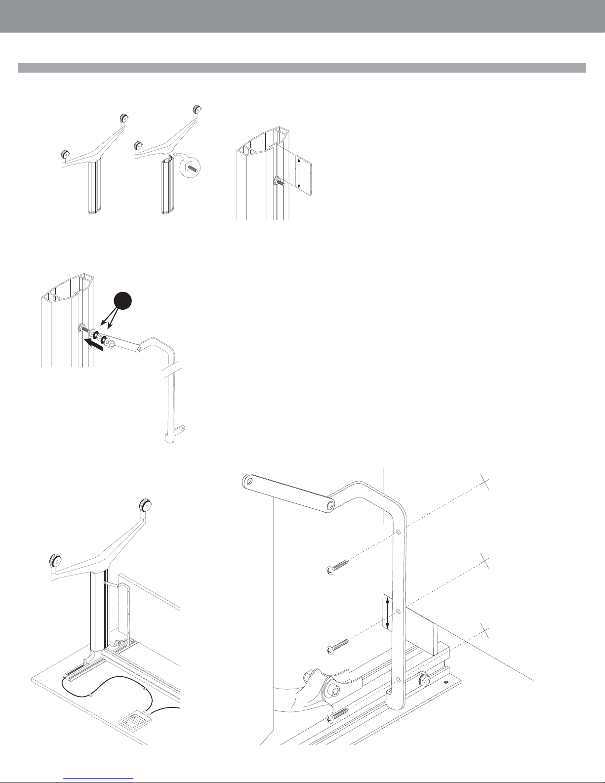
GLOBALContract
INSTALLATION GUIDELINES
Flip top tables
4. Unbolt the pre-installed foot from it’s column. Insert the slotted bolt in the channel.
Reconnect the foot and column. Tighten the bolt with washer and nut 4 7/8”
from the bottom at the foot connection.
4
5. Connect the modesty panel bracket as shown.
Insure that nylon washers (A) are installed on either side
of the modesty bracket.
A
• Fall 2017
7/8”
6. Attach modesty panel. Using guide block position panel 1 7/8”
below support beam and screw in place.
7/8”
1
Page • globalcontract.com77
Page 79
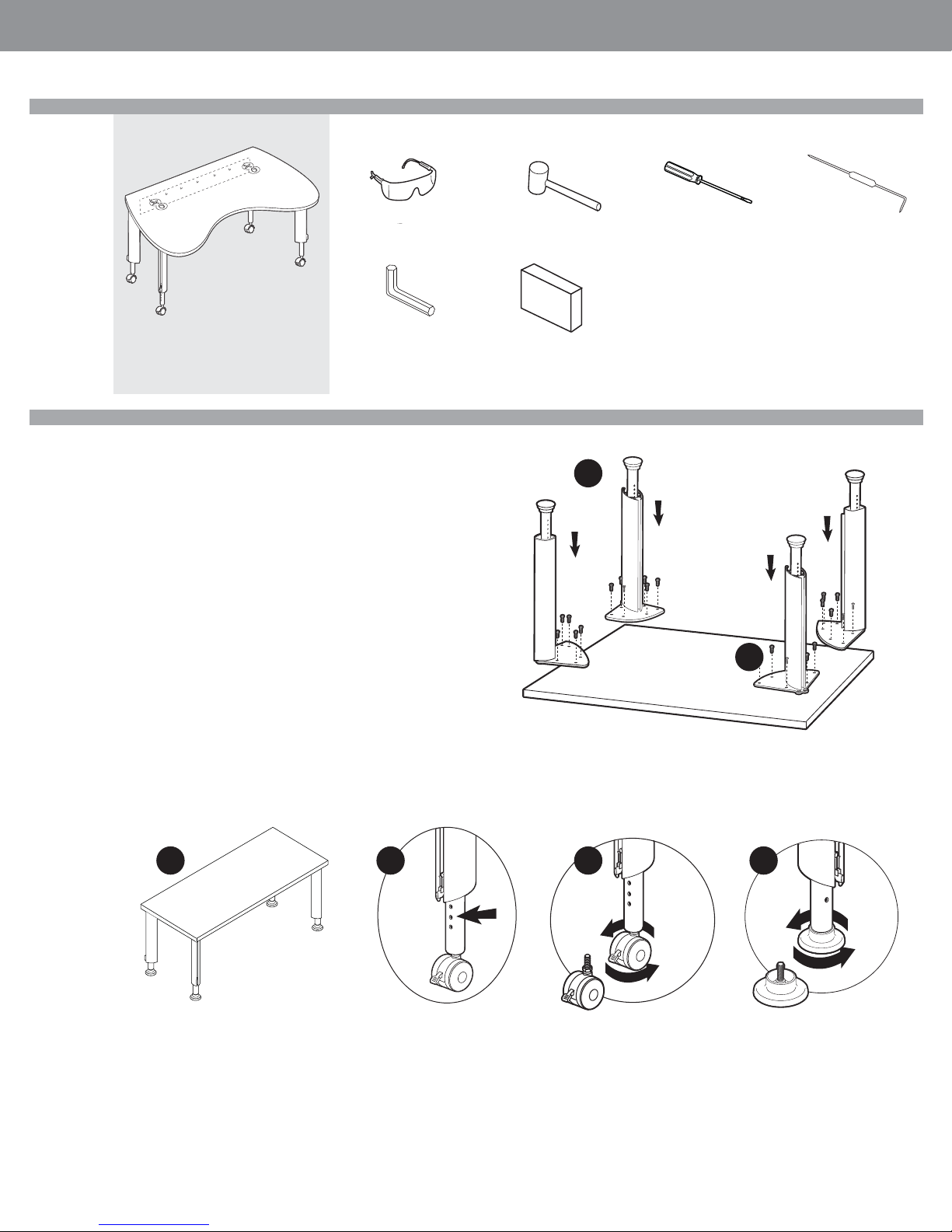
GLOBALContract
viceversa®
Required Tools
Safety Glasses
• Fall 2017
INSTALLATION GUIDELINES
Rubber Mallet
Screwdriver Metal Pick
Allenkeys
Leg attachment to surface
STEP 1: Place the worksurface on the fl oor upside down.
IMPORTANT:
Ensure there are no foreign items on the fl oor that could damage the fi nish of the
surface. It is recommended the installation of the legs be done on either a padded
blanket or cardboard.
STEP 2: Position the appropriate leg(s) over the 4 metal inserts located in the
worksurface, and attach with supplied bolts. Use 2 wood screws (1”x#10) to lock
each leg into position.
STEP 3: Once all legs are attached securely, invert the completed unit, locate it according to the installation plan.
STEP 4: The unit can now be leveled. There are nine holes on each leg for the purpose of adjusting the height of the unit. The holes are located at 1” increments.
Nylon Block
1
2
STEP 5 For fi ne-tuning of leveling, simply turn the leveling glide on the bottom of
the leg, or caster, until level is accomplished.
STEP 6: To change the leveling glide to a caster, or locking caster, remove the existing casting by threading it all the way out of the leg. Screw in the desired product,
and level as above.
3 4 5 6
•Pageglobalcontract.com 78
Page 80
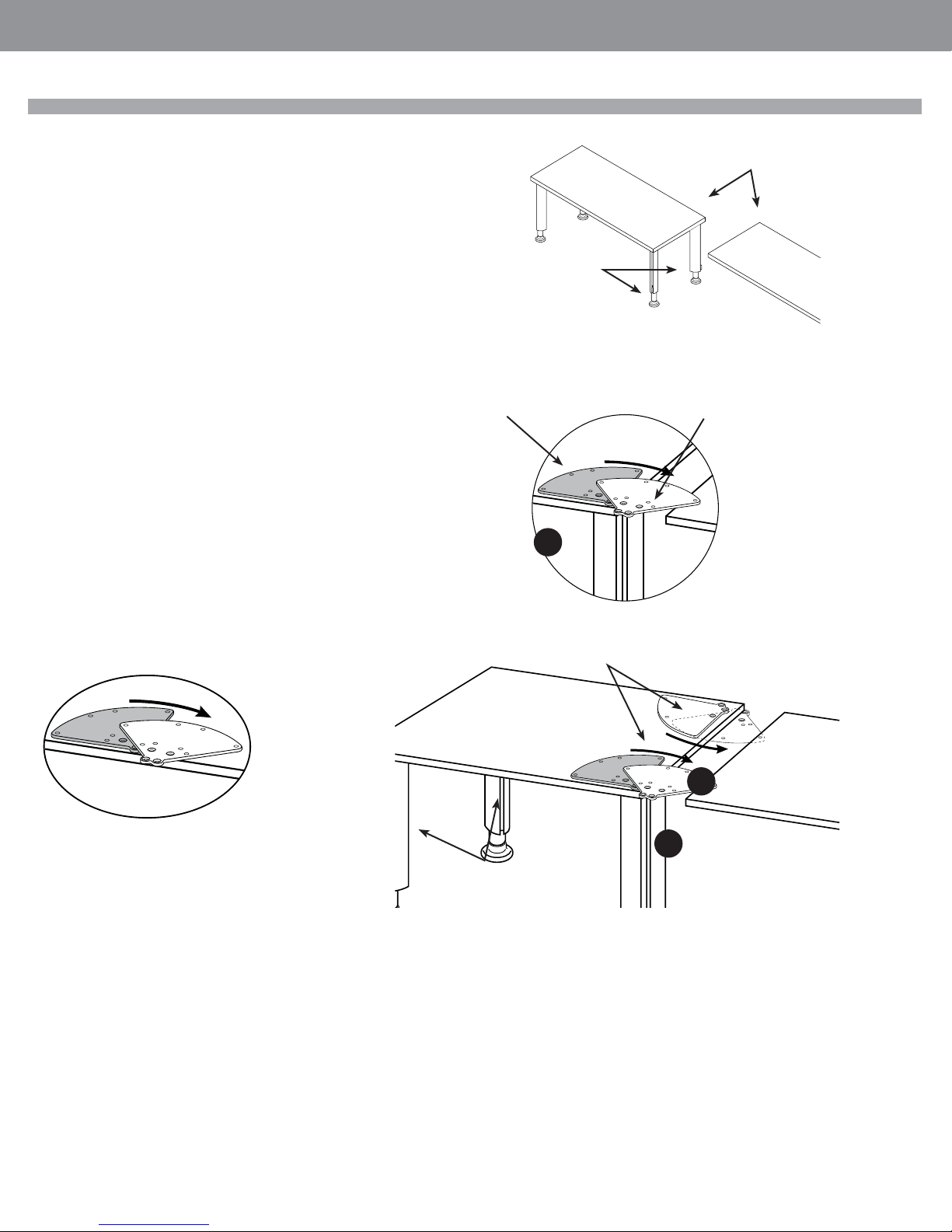
GLOBALContract
INSTALLATION GUIDELINES
Ganging Worksurfaces
Any worksurface with a rectilinear edge may be ganged to another surface with a
rectilinear edge. There are two scenarios involved.
The fi rst involves taking an already existing (installed) table, and ganging it to
another, or several.
The second involves installing from the beginning. In either scenario, it is important
to note, use only leveling glides to create a ganging application.
• Fall 2017
ganging surfaces
Scenario #1
STEP 1: With table in upright position, loosen screws on (2) table legs to be used to
gang to adjacent surface, Rotate table leg around 45 degrees.
STEP 2: Place ganging surface up to existing table and position top above exposed
ganging plate of legs. Align screw positions and secure.
Scenario #2
STEP 1: Assemble primary table by installing (2) fi xed legs and (2) ganging legs rotated at 45 degrees. (as per standard leg installation procedures with worksurfaces
on the fl oor upside down)
Invert table assembly exposing (2) legs with ganging plates
Assemble secondary table(s) by installing (2) remaining legs as per step 1 and
invert, position over primary table.
STEP 2: Place ganging surface up to existing table and position top above exposed
ganging plate of legs. Align screw positions and secure.
Repeat steps 1 through 2 to complete desired confi guration. Level accordingly.
loosen screws on (2) table
legs to be used to gang to
adjacent surface.
old position new position
1
2 ganging legs
Rotate centre legs 45 degrees so that leg base
assembles to both tables.
Page • globalcontract.com79
2 fi xed legs
1
2
Note: Table is shortened
for instructional clarity.
Page 81
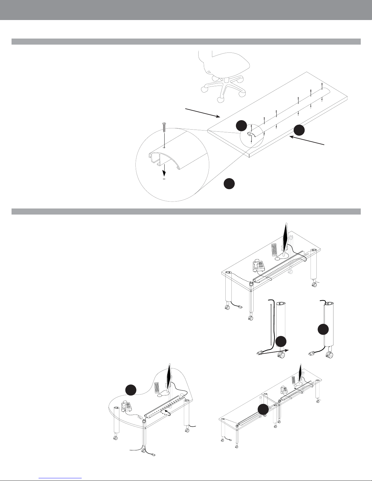
GLOBALContract
Wire Manager
The wire manager can be installed either after the unit has been inverted and in position, or while the worksurface is upside down on the fl oor.
STEP 1: Orient the extruded PVC wire manager so the opening for the wires is facing
the back of the worksurface.
STEP 2: Align the wire manager with the metal inserts located in the worksurface.
Install the six supplied 1/4-20-2” bolts into the holes and secure.
• Fall 2017
INSTALLATION GUIDELINES
worksurface is
upside down
on the fl oor
front of the worksurface
(chair side)
Wire Management
Viceversa® tables have wire management built right into the leg to neatly organize
electrical and communication cables from the worksurface to the fl oor.
Leg
STEP 1: Remove the plastic wire management cover to expose channel.
STEP 2: Lay in power and telephone cable up along leg and secure in place by snapping
back in the plastic cover.
Horizontal wire management
STEP 3: Excess cables can also be neatly stored below the worksurface from any location within the horizontal wire management tray . Wires may also be routed from table
to table along the wire management tray
2
1
back of the
worksurface
2
Combination wire management
STEP 4: The Dogbone tables come standard with (2) grommets in the surface for wire
management. Cables can be routed through the grommets, across the horizontal wire
manager then down the leg into wall, fl oor or electrifi ed panels.
2
1
plastic wire
management
4
3
•Pageglobalcontract.com 80
Page 82
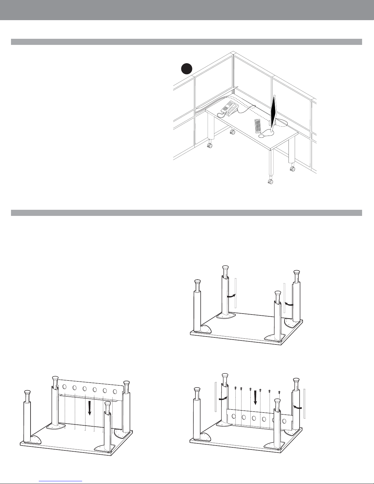
GLOBALContract
INSTALLATION GUIDELINES
WIre Management with Boulevard
Viceversa tables can manage wires externally routed to and from our Boulevard panel
system.
• Fall 2017
STEP 1: With the tables adjacent to boulevard panels, power and communication can
exit the Boulevard raceway directly into the horizontal wire management tray terminating
at any location atop the worksurface.
Modesty Panel
Viceversa tables can manage wires externally routed to and from our Boulevard panel
system.
STEP 1: Place the top on the fl oor upside sown.
1
NOTE: Ensure there are no foreign items on the fl oor that could damage the fi nish of the
surface. It is recommended the top be places on either a padded blanket or cardboard.
STEP 2: Remove the wire management covers from the legs.
STEP 3: Place side fl anges of the modesty panel into the cavity of each leg and slide
the top of the modesty panel to the underside of the worksurface. (The modesty panel
should be oriented so that the screws are on the inside or towards the user.
STEP 4: Drive the supplied screws through the holes in the modesty panel.
STEP 5: Shorten and replace the wire management covers onto the legs.
NOTE: When ganging two tops by sharing the legs, the metal modesty panel can not be
used.
When ganging two tops with metal modesty panel, specify two fl at brackets per join.
Page • globalcontract.com81
Page 83
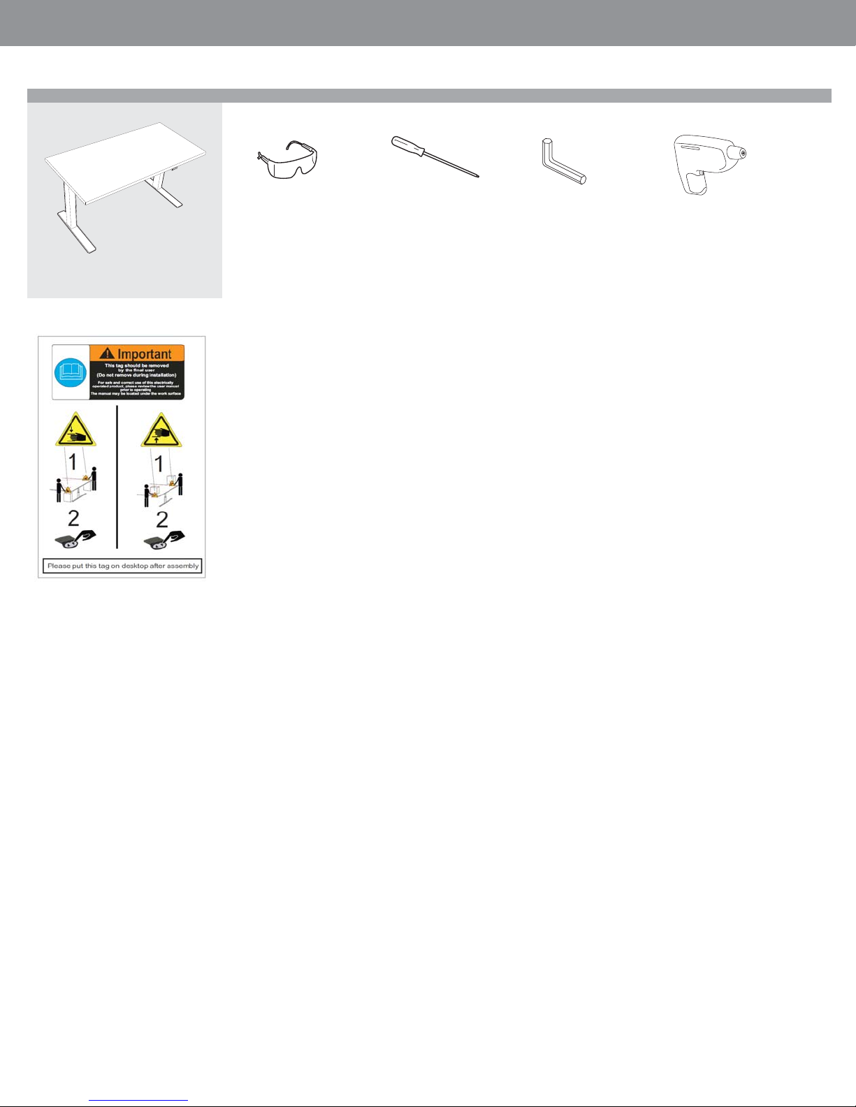
GLOBALContract
FreeFit
Required Tools
Safety Glasses Allenkeys Drill with Roberson BitRobertson Screwdriver
Warning leafl et and user manual should be left on the table after completed installation.
• Fall 2017
INSTALLATION GUIDELINES
•Pageglobalcontract.com 82
Page 84
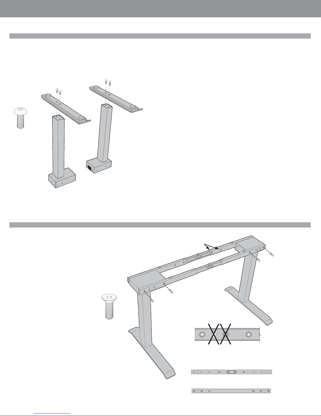
GLOBALContract
INSTALLATION GUIDELINES
Feet
Assemble the feet on the columns. Tighten screws fi rmly.
IMPORTANT: Make sure the correct screws are used. Using too
long screws may destroy internal parts in the column.
Screw Socket Round UNC 5/16- 18x5/8” Zn
• Fall 2017
Crossbars
Loosen screws to adjust crossbar length.
Screw socket CSK UNC
5/16 - 18x1” Zn
Do not use the two middle holes of the crossbars.
Page • globalcontract.com83
Adjustable crossbar
Fixed crossbar
Page 85
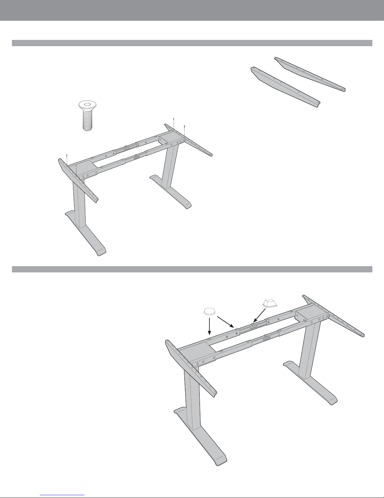
GLOBALContract
Sidebars
Fasten sidebars in threaded holes on top of crossbars with countersunk screws.
Various types of sidebars exist, some of which can be placed in optional positions.
The holes closest to the ends of the sidebar are dedicated for fi xing of work top but
any available hole can be used for this purpose.
Screw socket CSK UNC
1/4-20x5/8” Zn
• Fall 2017
INSTALLATION GUIDELINES
Right Hand / Left Hand
Sidebars
Bumpers
The work top is resting on the sidebars and on self-adhesive
rubber bumpers placed on the crossbars. The bumpers should
be placed as close to the fi xing screws for the work top as possible to keep the work top from bending.
The rubber bumpers come in two thicknesses. The thicker ones
are used on the C-channel. On fi xed crossbars the thick bumpers
are not used.
Bumper ø 1/2”x 1/8”
Transparent
Bumper 1/2”x 1/2”x1/4”
Transparent
Place the thin bumpers on the
tube next to the screw hole
and next to the tube edge.
Place the thick bumpers on
the C-channel next to the
screw hole.
Two sizes of wood screws for the work top are included
in the assembly kit. Wood Screw Round 8x3/4” Zn Wood
screw CSK 10x2-3/8” Zn
The shorter screws through sidebars. The longer screws
through crossbars.
•Pageglobalcontract.com 84
Page 86
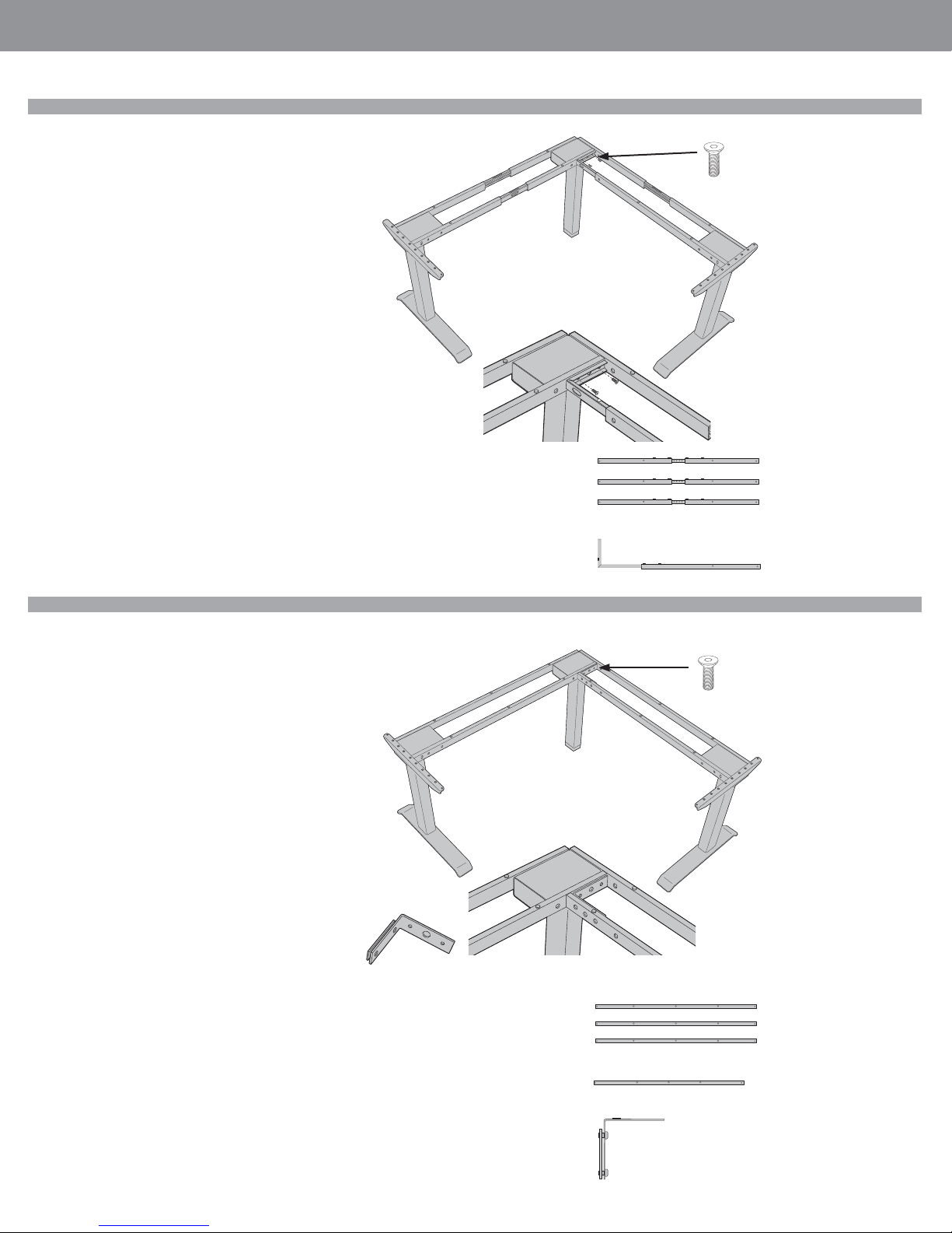
GLOBALContract
INSTALLATION GUIDELINES
3-Column 90° Telescopic Crossbars
Attach the crossbars on the long side of the housings. Tighten
screws fi rmly. IMPORTANT: Do not use the two middle holes of the
crossbars. Do not insert any object in the two middle holes as this
can damage electronic components.
Loosen the round headed screws on the cross-bars and adjust the
frame to desired width.
Fasten the screws on the crossbars.
3 regular telescopic crossbars and 1 special telescopic crossbar
with an angled C-channel are used.
• Fall 2017
Screw socket CSK
UNC 5/16-18x13/8” Zn
3-Column 90° Fixed Crossbars
3-Column 90º Table, Fixed Crossbars 3 regular fi xed crossbars
together with 1 regular fi xed crossbar 6” shorter than the other
three are used.
The assembly procedure is the same as for a 2-column table with
the exception that the angled C-channel mounts to the middle house
with one extra-long screw 1-3/8”.
3 Regular telescopic crossbars.
1 Special Telescopic crossbar.
No additional assembly kit.
Screw socket CSK
UNC 5/16-18x13/8” Zn
Page • globalcontract.com85
3 Regular fi xed crossbar.
Regular fi xed crossbar 6” shorter
than the other three crossbars.
Assembly Kit PR25 90º Angle
Page 87
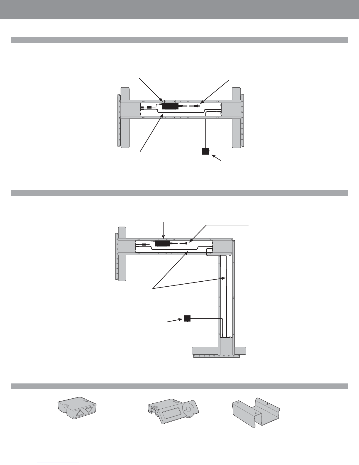
GLOBALContract
Electrical 2-Column
The handset is mounted at the front edge of the work top, screwed
to the underside with screws supplied with the unit.
Connect cables and power supply according to
• Fall 2017
INSTALLATION GUIDELINES
Power Supply D04 35V/2, 12A AC input 110-240V, 50-60Hz
Cable LinBus iDrive
Electrical 3-Column
Cable USA 2-pol IEC C7
ASM Light Handed w/Screws
Power Supply D04 35V/2, 12A AC input 110-240V, 50-60Hz
Cable USA 2-pol IEC C7
Cable LinBus iDrive
ASM Light Handset
ASM Light Handed w/Screws
Handset w Display
Holder for power supply, hooks over crossbar or
screws into worksurface.
•Pageglobalcontract.com 86
Page 88
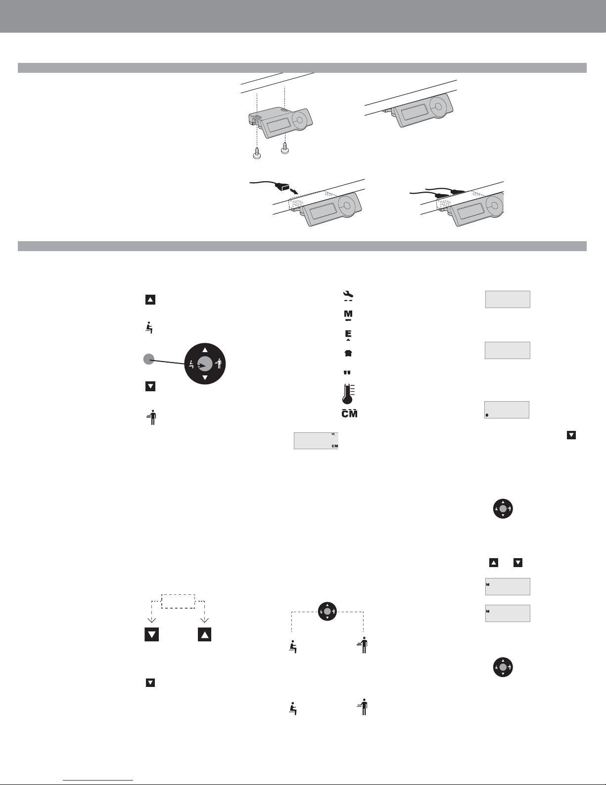
GLOBALContract
INSTALLATION GUIDELINES
Jog Wheel Hadset Manual
Use the 2 attached screws for fi xing to the ta-ble top. If the thickness of the table top is less than 18 mm please use shorter screws.
In situation of sloped edges of the table top there could be need for
a third fi xing point. When screw will be chosen consider that 13mm
will be “lost” due to the hand switch.
Connect the Bus cable to the hand switch.If appropriate, connect
two bus cables to the hand switch.
Wheel Controls
• Fall 2017
Wheel icons:
How to understand the symbols.
-Adjust the table upwards
-Scroll in the menu
-Adjust the table to sitting position
-Scroll to left in the menu
-Menu, press for the menu
-Enter, confirm your selection
-Adjust the table downwards
-Scroll in the menu
-Adjust the table to standing position
-Scroll to right in the menu
Reset:
If some components are changed
(columns, motor, control for motors
etc) there will be need for a “forced”
reset. Please follow the instruction
below.
Forced Reset:
If the reset symbol will be visible,
please press (2 bottoms) min 7 sec,
the reset symbol will show up.
7 sec
Display layout:
Explanation of the symbols.
Tool
Memory
Error codes
Reset
Imperial, inches
Thermometer
Metric, centimeter
40
15 sec –sleep mode
Display backlight will go to sleep
mode after 15 sec of inactivity.
Quick Start:
Run/Drive the table to the position
you will store, sitting or standing.
(Two different processes)
Press the menu button and hold for
more than 2 sec.
Start Up:
Initial display communication.
---
Under normal condition the display automatically went to display layout as right in 2 to 5
sec.
25.2
If the system feel a incomplete homing the
homing icon well be visible.
---
Press the “down” symbol for homing.
How to go to memory:
Press the menu button less than 2 sec.
Use arrow up and down to navigate to
memory setting.
1
5
Hold Menu button to go to the stored position.
Then press and hold “down” symbol
until the columns have gone to lowest
level.
Page • globalcontract.com87
Press “sitting” left
side (memory 1)
Press and hold
Go to memory 1
Press “standing”
right side (memory 2)
Press and hold
Go to memory 2
Page 89
GLOBALContract
Wheel Controls
• Fall 2017
INSTALLATION GUIDELINES
How to set memory:
Run/Drive the table to the position you will store,
sitting or standing.
(This device have 5 memories position memories)
Press menu button + “stand” icon 1 time to come
to set memory menu.
Use arrow up and down to navigate to set memory
setting.
1
5
Press Menu/Enter, and the value are stored.
The display confi rm by fl ashing 3 times and then
returns to normal mode.
Upper limit:
Set the upper limit if there are limited
space in height.
Press menu button + “stand” icon 3
times to come to set memory menu.
UL
Press Menu/Enter to confi rm. Press Menu/Enter to confi rm.
Adjust the fi gures to the chosen level
with the arrows up or down.
Units:
Choose between metric or imperial
system.
Press menu button + “stand” icon 5
times to come to set memory menu.
UN
Adjust the fi gures to the chosen level
with the arrows up or down.
50.0
Press Menu/Enter, and the value are
Press Menu/Enter, and the value are
stored.
stored.
Calibrate:
Measure the distance between the fl oor and the top
of the table sheet.
Press menu button + “stand” icon 2 times to come
to calibrate menu.
CAL
Press Menu/Enter to confi rm
Adjust the fi gures to the selected value with the
arrows up or down.
28.0
Press Menu/Enter, and the value are stored.
Please note that the fi gures count
from the table top surface.
Lower limit:
Set the lower limit if there are device/
equipment which could create a risk
of pinching or risk for table damages.
Press menu button + “stand” icon 4
times to come to set memory menu.
LL
Press Menu/Enter to confi rm
Adjust the fi gures to the chosen level
with the arrows up or down.
27.5
Reset Away:
Press menu button + “stand” icon 6
times to come to set memory menu.
RES
Press Menu/Enter, and the value are
stored.
Press ‘down” and hold until the columns
have gone to the lowest position.
Do reset if any parts have been changed
of if you discover interference between
the columns.
Error codes:
3
1. Hard stop
2. Back off
3. Soft top
4. Waiting for button
5. Waiting for button release.
6. Motor lost
Press Menu/Enter, and the value are
stored.
Please note that the fi gures count from
the table top surface/ calibrated level.
Overheating. Thermometer fl ashing,
wait 10 minutes for motor cooling.
•Pageglobalcontract.com 88
Page 90
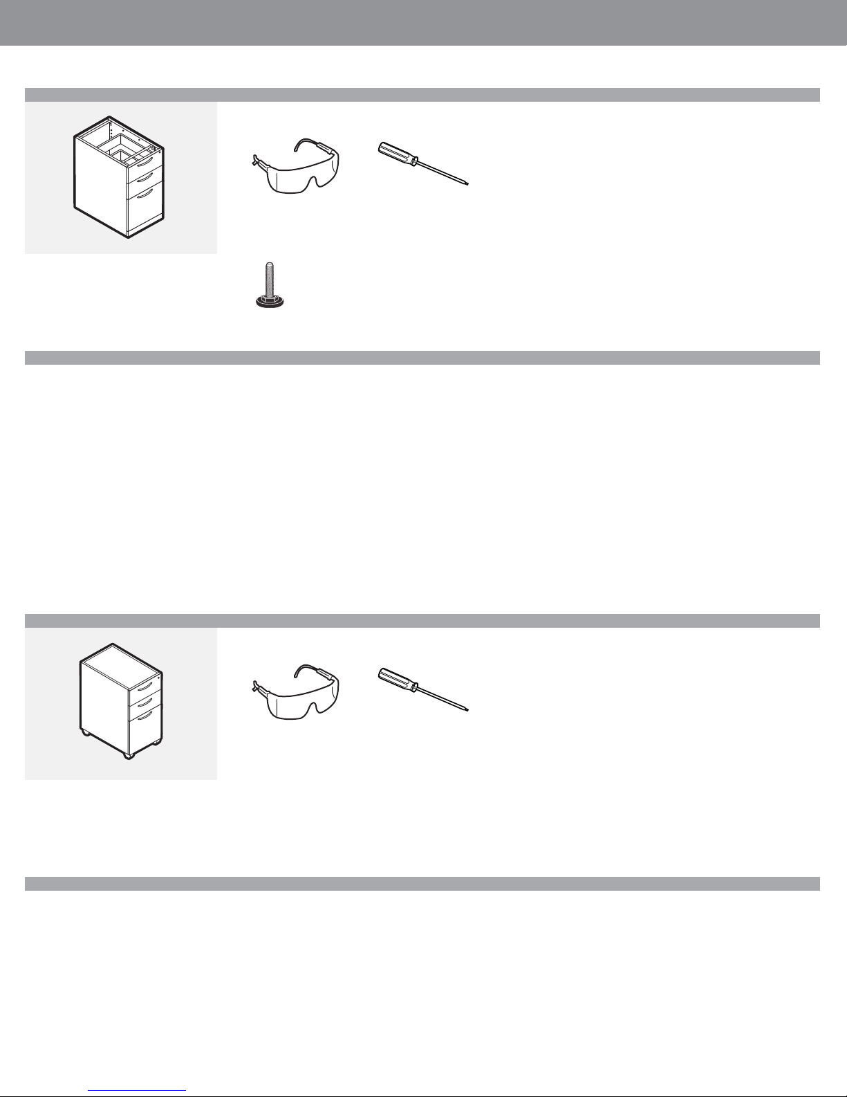
GLOBALContract
INSTALLATION GUIDELINES
L2PBBFxx
Required Tools
Safety Glasses
Included Hardware
Leveler
L007250037
NOTE: Open and assemble only one product
at a time to avoid a potential mix-up of parts
and hardware.
It is adviseable to assemble the unit on a
carpet to avoid scratches.
Assembly
STEP 1: Unpack and inspect individual pieces for damages or missing hardware.
STEP 2: Handles for Pedestals are Shipped Installed on the inside of the cabinet.
Remove handle from the inside of the cabinet and re-install with the same screws
on the front of cabinet.
a. Levellers for pedestals are shipped inside the unit. Install in threaded
brackets on the bottom of the unit and level accordingly.
#2 Screwdriver Roberson
• Fall 2017
Installation For Similar Products
* Freestanding Storage Including
Pedestals, Freestanding and worksurface supporting CPU Units
Laterals, Freestanding and Worksurface supporting One high storage products.
Storage Towers
Storage and Wardrobe cabinates
L2PBBFxxMIT
Required Tools
Safety Glasses
NOTE: Open and assemble only one product
at a time to avoid a potential mix-up of parts
and hardware.
It is adviseable to assemble the unit on a
carpet to avoid scratches.
#2 Screwdriver Roberson
Assembly
STEP 1: Unpack and inspect individual pieces for damages or missing hardware.
STEP 2: Handles for Pedestals are Shipped Installed on the inside of the cabinet.
Remove handle from the inside of the cabinet and re-install with the same screws
on the front of cabinet.
a. Casters are shipped installed.
Page • globalcontract.com89
Page 91
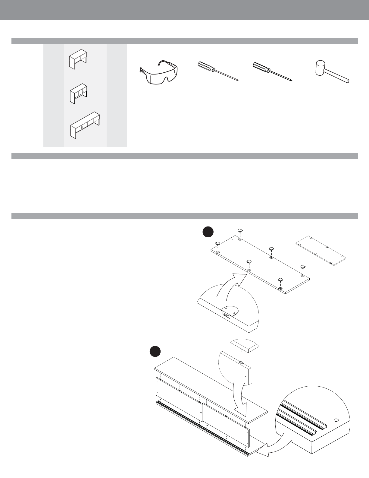
GLOBALContract
L2HHxxHxx • All Storage Hutches
General Assembly
STEP 1: Unpack and inspect individual pieces for damages or missing hardware
STEP 2: Pick a clean unobstructed area to assemble desk.
STEP 3: Installation of Hutch on Base unit. There are pre-installed strips of double
sided Tape on the bottom of the Unit. Peel off protective cover and place unit onto
base as required.
* Placement of the hutch should be such that the side gables of the Hutch
INSTALLATION GUIDELINES
Required Tools
Safety Glasses Screwdriver #2 Phillips Screwdriver #2 Robertson
NOTE: Open and assemble only one product
at a time to avoid a potential mix-up of parts
and hardware.
It is adviseable to assemble the unit on a
carpet to avoid scratches.
storage unit line up with the gables on the base unit. Off module installation
of storage hutches is not recommended.
*Hutches with Sliding doors are shipped assembled with Sliding doors uninstalled
• Fall 2017
Rubber Mallet
Sliding Door Assembly
STEP 4: Layout Sliding Doors an clean unobstructed surface, orient top and
bottom of doors based on handle positions.
STEP 5: Bottom Casters and Top Glides are provided. Place Bottom Caster
pieces in cut-outs along bottom edge of both doors and screw into place with
provided screws. Do the same for the Top Glides.
a. Insure that the top glide is “retracted” using the slide adjustment.
STEP 6: Place the fi rst door in back rear track engaging the bottom caster into
the track, tip door in and line up with upper rear track. Extend the top glide using adjustment slide adjustment for each top glide.
a. Repeat for door on front track.
STEP 7: Install provided handles into pre-drilled hole positions on left and right.
6
5
•Pageglobalcontract.com 90
Page 92
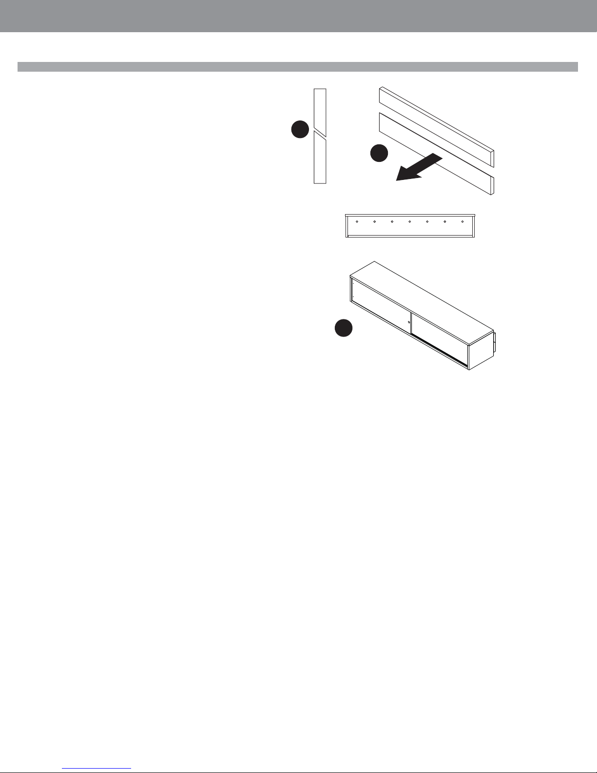
GLOBALContract
INSTALLATION GUIDELINES
Wall Mount Storage
Licence wall mount overheads are shipped fully assembled.
STEP 1: Placement on a wall, insure that the wall has load bearing capability.
Hardware to attach to a wall is not provided as different hardware is required for
different types of walls. In ALL cases, it is important to use fastening hardware
suitable for the load and the type of wall.
STEP 2: Wall mount bracket is 2 laminate boards cut with 45 degree angle at
top so that when placed together they will fully engage. Bottom board will be
mounted to the wall with “high” side facing out from the wall.
1
• Fall 2017
Installed on the overhead
2
STEP 3: Once mounted and secured, the overhead can be placed on the wall engaging wall mount hardware. On the inside of the cabinet, drive a screw though
the back wall of the overhead into the wall mounted laminate strip to full secure.
Front away from wall
3
Page • globalcontract.com91
Page 93
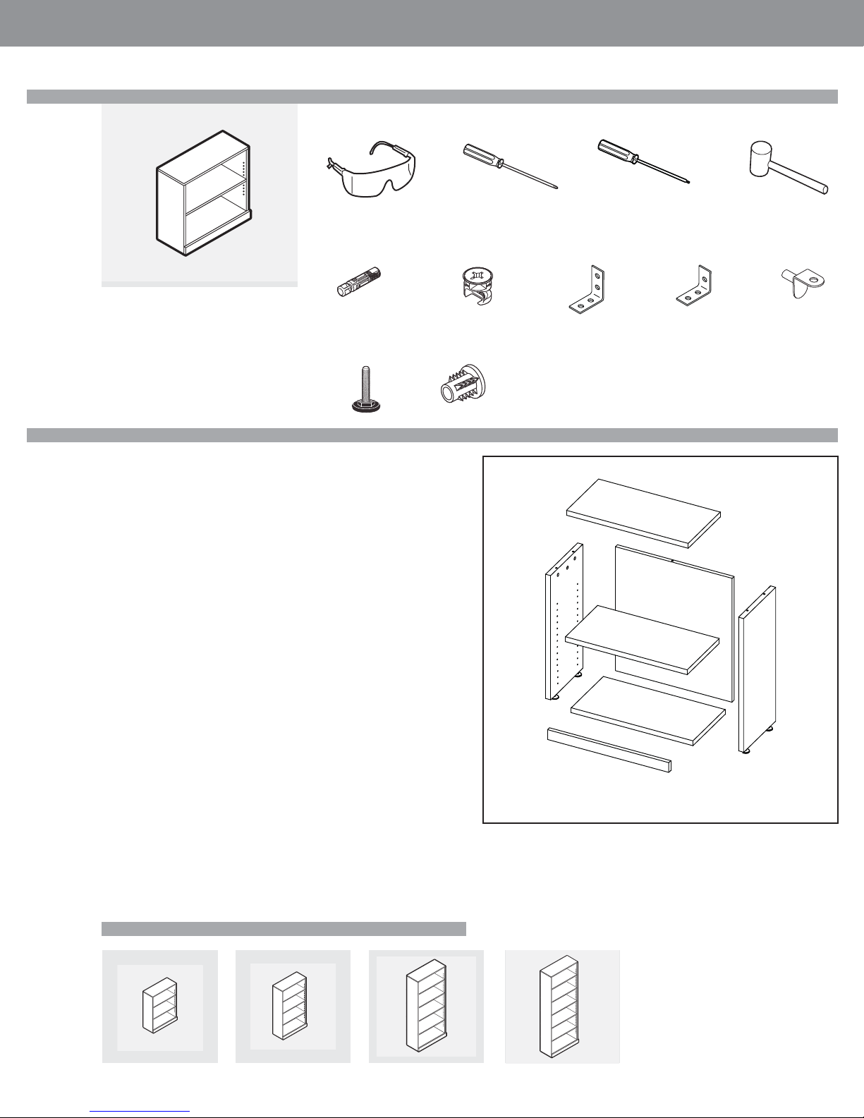
GLOBALContract
L2B2Hxxxx • Bookcase
NOTE: Open and assemble only one product
at a time to avoid a potential mix-up of parts
and hardware.
It is adviseable to assemble the unit on a
carpet to avoid scratches.
INSTALLATION GUIDELINES
Required Tools
Safety Glasses Rubber MalletScrewdriver #2 Phillips Screwdriver #2 Robertson
Included Hardware
Connecting Dowel
L004250004
Leveler
L007250037
Connecting Cam
L007250002
“T” Nut Insert
L007250039
“L” Bracket
L005650065
“L” Bracket
L005650064
• Fall 2017
Shelf Support Pin
L007250013
Assembly
STEP 1: Unpack and inspect individual pieces for damages or missing hardware
STEP 2: Pick a clean unobstructed area to assemble desk. It is advisable to assembly of this product upright.
STEP 3: Lay bottom piece down with connecting cams facing up.
a. Lay baseboard along front edge (edge without quick fi t cam). Space
baseboard with equal overhang on both sides and insure that the top edge
of baseboard and the top of bottom shelf are aligned. Using the Small “L”
bracket and #8 x ¾ wood screws, secure as shown.
STEP 4: Lay back panel on ground face up, insert connecting dowel in bottom
center pre-drilled hole.
a. Connect bottom assembly to the back board by lining up connecting
dowel to connecting cam as shown. Using screwdriver, turn connecting
cam to 2 O’clock position to secure.
STEP 5. Lay either left or right end panel on ground with exposed holes
for shelf adjustment facing up. Insert connecting dowels in pre-drilled
holes on perimeter.
a. Pick up assemble pieces and line up connecting dowels with connecting
cams. Using screwdriver, turn cam to 2 O’clock position to secure.
STEP 6: Repeat for opposite side.
STEP 7: On the bottom, install one large “L” bracket in each corner using #8 x ¾
woods screws provided. Install levellers into T nut inserts, use mallet to install in
pre-drilled holes on left and right end panels
STEP 8: Stand assembly upright.
STEP 9: Install connecting dowels in pre-drilled holes on top edge of the end panels
and the back panel. Place top panel onto assembly lining up the connecting dowels
with the connecting cam. Using screwdriver, turn quick fi t cam to 2 O’clock position
to secure.
STEP 10: Arrange shelf support pins as required and install shelves. Note that you
are able to secure shelves in place by screwing the shelf support pin to the underside of the shelf after fi nal positioning has been done.
TOP
END PANEL
BACK BOARD
SHELF
BOTTOM
END PANEL
BASEBOARD
Installation For Similar Products
L2B3Hxxxx L2B4Hxxxx L2B5Hxxxx L2B6Hxxxx
•Pageglobalcontract.com 92
Page 94
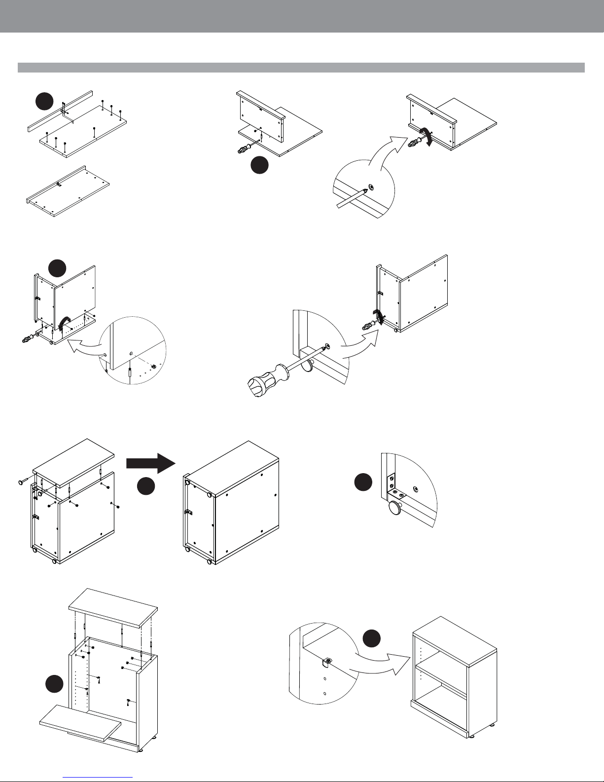
GLOBALContract
INSTALLATION GUIDELINES
3
4
5
• Fall 2017
6
9
Page • globalcontract.com93
7
10
Page 95
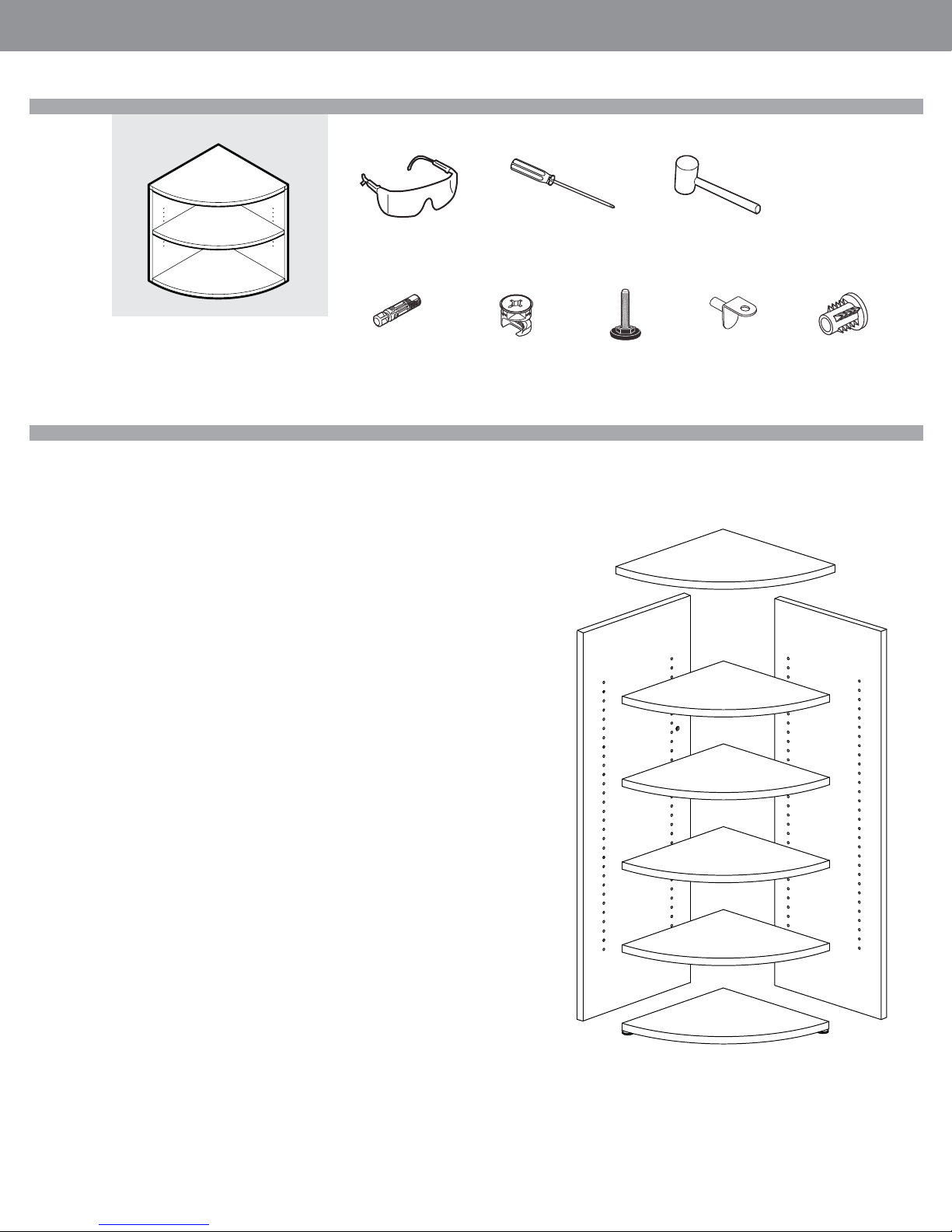
GLOBALContract
L2BC2Hx • Corner Bookcase
NOTE: Open and assemble only one product
at a time to avoid a potential mix-up of parts
and hardware.
It is adviseable to assemble the unit on a
carpet to avoid scratches.
Assembly
STEP 1: Unpack and inspect individual pieces for damages or missing hardware
INSTALLATION GUIDELINES
Required Tools
Safety Glasses Rubber MalletScrewdriver #2 Phillips
Included Hardware
Connecting Dowel Connecting Cam Glide Shelf Support
• Fall 2017
“T” Nut Insert
L007250039
STEP 2: Pick a clean unobstructed area to assemble desk. It is advisable to assembly of this product upright.
STEP 3: Lay short back panel with exposed holes for shelf adjustment facing up.
Insert connecting dowels in pre-drilled holes along bottom.
a. Attach bottom shelf by ling up installed connecting dowels with connecting
cam installed on the bottom of the shelf. Using screwdriver, turn connecting
cam to 2 O’clock position to secure.
STEP 4: Lay long back panel on ground with exposed holes for shelf adjustment
facing up. Install connecting dowels in pre-drilled holes on the back side and along
bottom.
STEP 5: Attach assembled short panel with bottom by lining up the connecting
dowels with the connecting cams. Using screwdriver, turn quick fi t cam to 2 O’clock
position to secure. Install levellers into T nut inserts, install into pre-drilled holes on
the bottom using mallet.
STEP 6: Stand assembly upright.
STEP 7: Install connecting dowels in pre-drilled holes on top edge the end panels.
Place top panel onto assembly lining up the connecting dowels with the connecting
cam. Using screwdriver, turn quick fi t cam to 2 O’clock position to secure.
STEP 8: Arrange shelf support pins as required and install shelves. Note that you
are able to secure shelves in place by screwing the shelf support pin to the underside of the shelf after fi nal positioning has been done.
TOP
SHELF
END PANEL END PANEL
BOTTOM
•Pageglobalcontract.com 94
Page 96
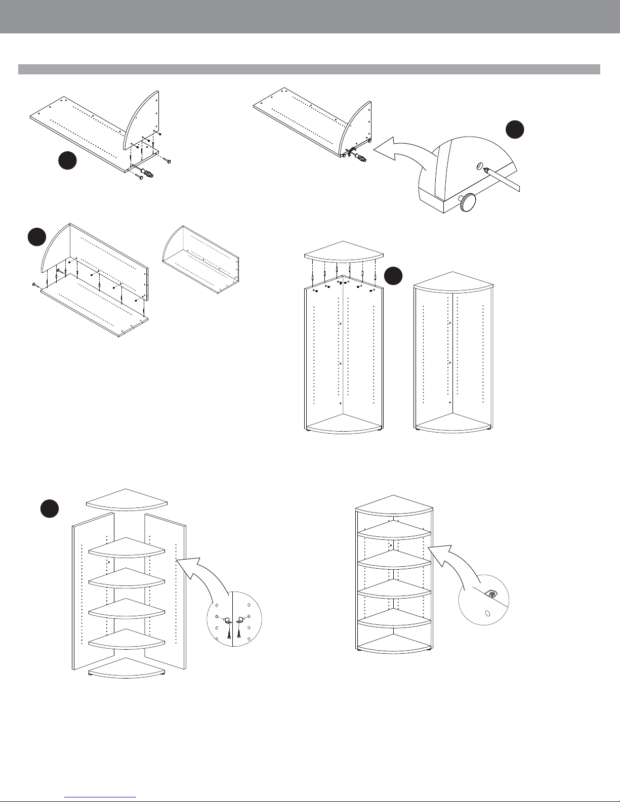
GLOBALContract
INSTALLATION GUIDELINES
3
5
• Fall 2017
2
7
8
Page • globalcontract.com95
Page 97
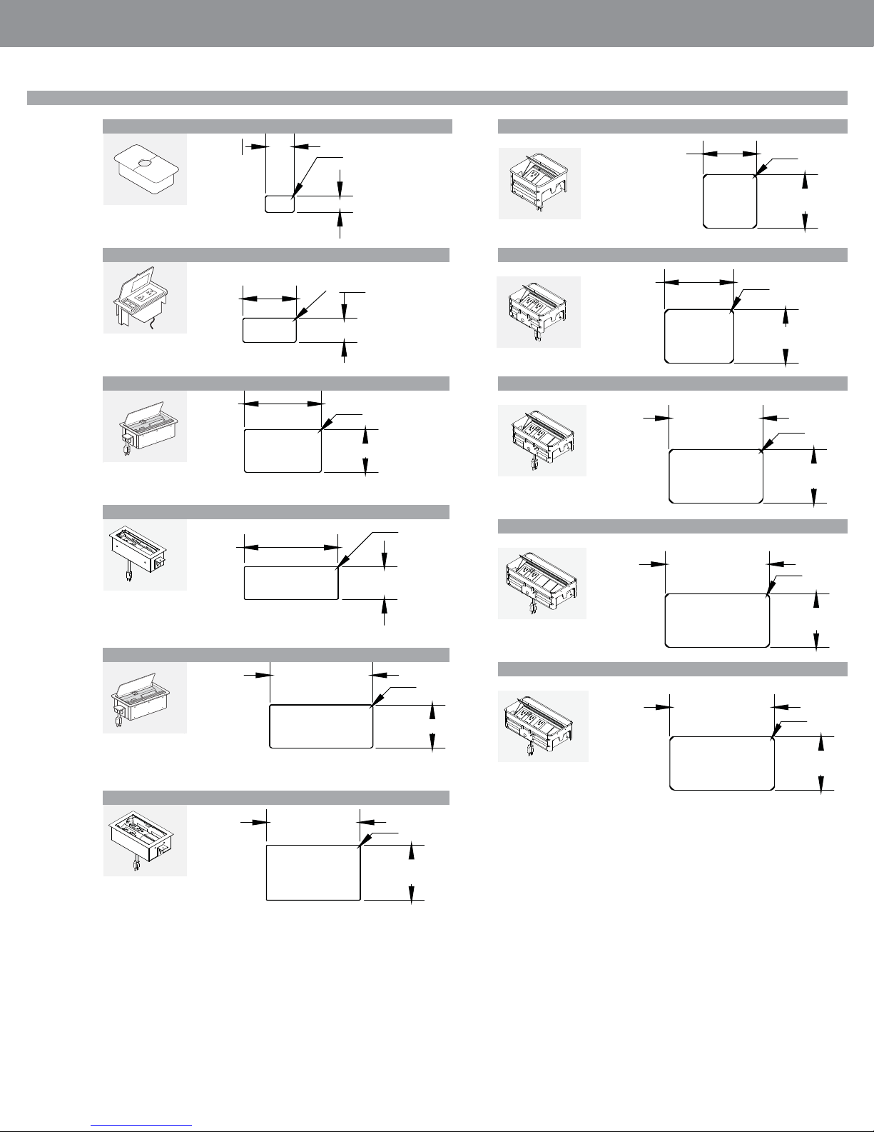
GLOBALContract
Grommet Cut Dimensions (inches)
BG5 ESMR101A
3.23
R0.25
• Fall 2017
INSTALLATION GUIDELINESINSTALLATION GUIDELINES
ESMRH101A
6.00
R0.50
MSPDM
LCTM101
LRTM101
5.95
8.60
10.50
1.85
R0.25
2.72
R0.25
4.80
3.63
R0.10
ESMR201A
ESMRH201A
ESMR202A
ESMRH202A
ESMR203A
ESMRH203A
7.73
10.50
11.71
6.00
R0.50
6.00
R0.50
6.00
R0.50
LCTM102
LRTM202
11.55
10.50
4.80
6.13
R0.25
R0.10
6.00
ESMR302A
ESMRH302A
11.71
R0.50
6.00
•Pageglobalcontract.com 96
Page 98
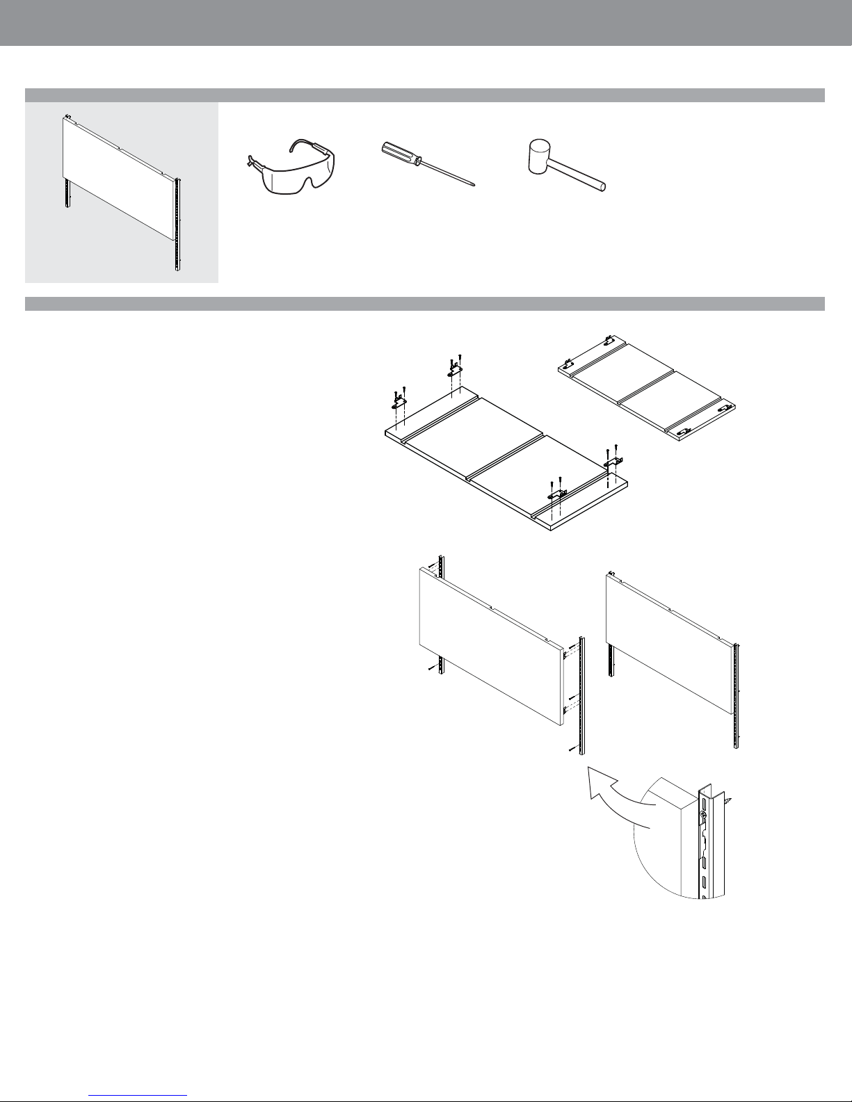
GLOBALContract
INSTALLATION GUIDELINES
LTB20 • Tackboard for wall mounted units
Required Tools
Safety Glasses Rubber MalletScrewdriver #2 Phillips
NOTE: Open and assemble only one product at a time to avoid a potential mix-up of
parts and hardware.
It is adviseable to assemble the unit on a carpet to avoid scratches.
Tackboard Instillation
Provides a tackable surface for notes and memos.
Mounting brackets for installation included.
Wall Rails (BHV01 and BHV02) must be ordered separately. Please see the
Boulevard Systems Pricelist.
Tackboard are to be installed directly to an existing wall
using vertical wall rails.
*Installation instruction is shown using BHV01 & BHV02 vertical wall
rails from the Global Contract Boulevard price list. Equivalent wall
mount brackets may be used as long as it uses standard 1” incremental slots
• Fall 2017
STEP 1: Based on width of the tackboard, see example dimension, vertical
Wall rails are to be attached to the wall.
*Hardware to attach to the wall are not provided and should be selected
Based on the type of wall you are mounting too.
STEP 2: Spacing of the wall rails using the example, measurement
dimension is from slot to slot for placement.
STEP 3: Make sure wall rails are vertical and parallel to each other, insure
that slots are level between rails.
STEP 4: Tackboard is shipped with the hardware installed from the factory.
Install by angling the top into desired slots at appropriate height and
rotate the bottom into position insuring the bottom brackets engage into
the vertical rails.
STEP 5: You may be require to use an mallet to gently tap the top of the
Tackboard to fully engage the brackets.
BHV01
BHV01
Page • globalcontract.com97
Page 99
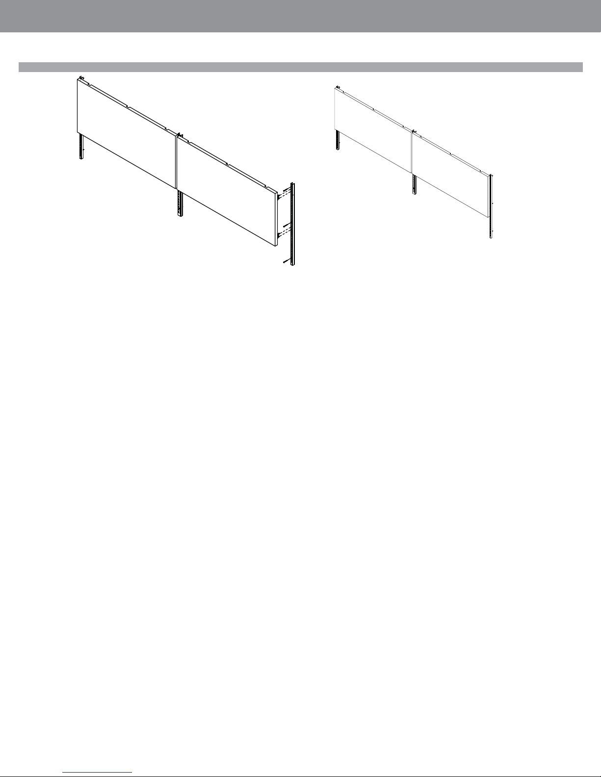
GLOBALContract
LTB20 • Tackboard for wall mounted installation, side by side
LTB20XX
BHV01
• Fall 2017
INSTALLATION GUIDELINES
LTB20XX
BHV02
BHV01
•Pageglobalcontract.com 98
Page 100

GLOBALContract
GLOBALContract
GLOBALContract
THE GLOBAL GROUP SHOWROOM
1350 Flint Road, Toronto, Ontario, M3J 2J7
Sales & Marketing • TEL: 1-877-446-2251 • FAX: 416-667-0338
Customer Service • TEL: 416-739-5000 • FAX: 800-361-3182
VANCOUVER SHOWROOM
3823 Still Creek Avenue Burnaby, BC, V5C 4E2 • TEL: 604-432-1701
EDMONTON SHOWROOM
17716 107 Avenue NW Edmonton, AB, T5S 1G8 • TEL: 780-444-8922
CALGARY SHOWROOM
302 - 237 8 Avenue SE Calgary, AB, T2G 5C3 • TEL: 403-250-7770
WINNIPEG SHOWROOM
1-1080 Waverley Street N Winnipeg, MB, R3T 5S4 • TEL: 204-925-3350
OTTAWA SHOWROOM
251 Laurier Avenue West, 4th Floor, Ottawa, ON, K1P 5T6
• July 2012
• June 2016
• Fall 2017
MONTREAL SHOWROOM
980 St-Antoine rué Ouest Montreal, bureau 200, QC, H3C 1A8 • TEL: 514-866-4331
HALIFAX SHOWROOM
1310 Hollis Street, Suite 150, Halifax, NS, B3J 3P3 • TEL: 902-422-7434
QUEBEC SHOWROOM
Complex Lebourgneuf 2, 815, boul. Lebourgneuf, Suite 502 Quebec, QC, G2JOC1 • TEL: 418-653-6111
Visit us on the Internet at globalcontract.com
Page • globalcontract.comH.16
Page • globalcontract.com99
Page • globalcontract.comH.14
 Loading...