

Global Contract Diet Installation Manual

Installation Manual
2017
ISO 9001:2015OHSAS 18001:2007 ISO 14001:2015
REVISED: FALL 2017
Visit us on the Internet at globalcontract.com • (416) 739-5000
Global Contract Inc. 565 Petrolia Road
North York, Ontario, M3J 2X8

GLOBALContract
TABLE OF CONTENTS
• Summer 2017
Panels
Panel Connector
Off Module panel Connector
Wall Adapter
Diet to Boulevard Slot Connector
Diet to Boulevard Connecting Kit
Diet Freestanding Panel Mobile Kit
Diet Panel Gap Filler Installation
90 Degree Confi gurations
Electrical
Diet Electrical
Diet Electrical Components
Diet Electrical Installation
Diet Communication Installation
Cable management
Worksurfaces
Worksurface Support
Worksurface Universal Flat Bracket
Gable Leg
Pedestal Bracket / Corner Plate
Transaction Bracket
Combining Diet and Boulevard Worksurfaces
Off-Module Cantilever
P.03
3
4
5
6
8
9
10
11
P.12
12
13
14
16
18
P.20
20
21
22
23
24
25
26
Storage
Storage
Open Shelf
Off - Module Shelf
DSADA Easy-Up Diet Overhead
P.27
27
28
29
30
Please contact your Global Contract Service Representative at 416-739-5000 for
any questions or concerns.
NOTE: Any alterations to listed components will void the manufacturer’s warranty.
The manufacturer will not be responsible for any damage or bodily harm caused
by alterations in accordance with national or local electrical codes and manufac-
Page • globalcontract.com2
turer’s specifi cations. In accordance with the manufacturer’s policy of continual
product improvement, the product presented in this document is subject to
change without notice or obligation.24
GLOBALContract
Panel Connector
Every panel ships with a connecting kit comprising hinges, spacers, screws and hinge
pins. Not all pieces included in the connecting kit might get used with every panel (connecting two stand alone panels at 90°, for example, will only require installation of two
hinge / spacer sets at the top and bottom of each panel). The remaining pieces included
in the connecting kit should be stored on site to be available for future reconfi gurations.
Location of connecting hinge / spacer and hinge / hinge set on panels is predetermined
by location of double holes, pre-drilled in panel verticals. There are pairs of holes located
always at the panels’ bottom and top. In addition, a 54” high panel will have a pair at 42”
height (to connect to 42” high adjacent panel) and a 66” high panel will have additional
pairs at 42” and 54” height (to connect to 42” and 54” adjacent panels).
NOTE: When connecting 66” high partly glazed panels, use additional set of connectors
at 42” height.
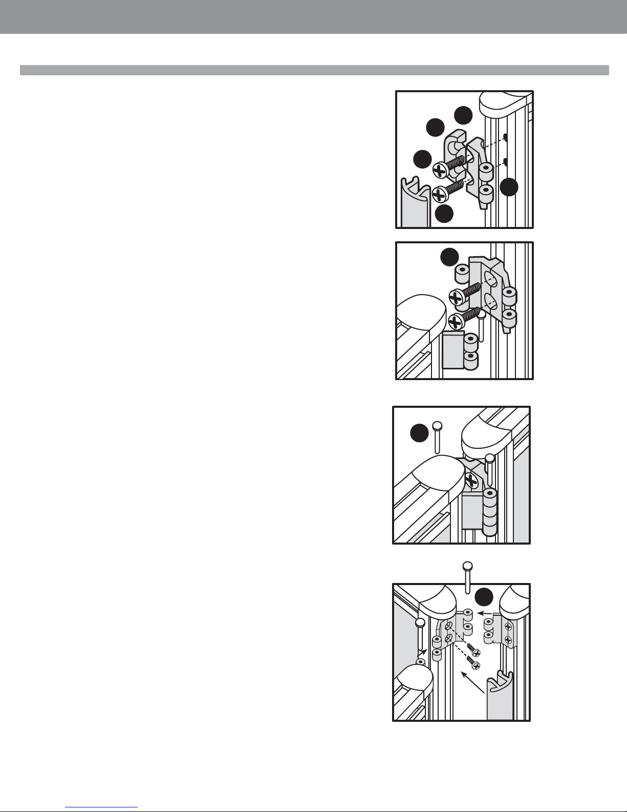
In order to install panel connectors to connect two panels at fl exible angle,
STEP 1: remove vertical edge trim,
STEP 2: position spacer A and hinge B over pre-drilled holes at desired height,
STEP 3: secure with two supplied screws (Do not over tighten!) and snap the
vertical edge trims back in place.
Set the panels to desired angle. Insert top and bottom pins. In order to connect two
straight panels (180°),
• Summer 2017
INSTALLATION GUIDELINES
2
A
3
B
1
4
STEP 4: Remove vertical edge trims, position two hinges over pre-drilled holes at
desired height and secure with two supplied screws on both panels. Do
not over tighten! Snap vertical edge trims back in place.
STEP 5: Level the fi rst panel, position the second panel so that all hinges overlap
and insert four pins (two at the top; two at the bottom).
STEP 6: To connect 3 panels in a 90°, 3 way confi guration, remove panel vertical
edge trims and install two spacer / hinge sets (top and bottom) on both
wing panels.
Install two hinge / hinge sets (top and bottom) on the panel that is going
to be installed between the wing panels.
Replace vertical edge trims, level the fi rst panel, position wing panels so
that all hinges overlap and insert four pins (two at the top; two at the
bottom) as you go along.
STEP 7: To connect three panels in a 120°, three-way confi guration (or four
panels in a 90°, four-way confi guration.
Remove panel vertical edge trims and install two hinge / hinge sets (top and bottom) on all panels.
Replace vertical edge trims, level the fi rst panel, position remaining panels so that
all hinges overlap and insert four pins (two at the top; two at the bottom) as you
go along. Level the whole panel assembly.
5
6
•Pageglobalcontract.com 3

GLOBALContract
INSTALLATION GUIDELINES
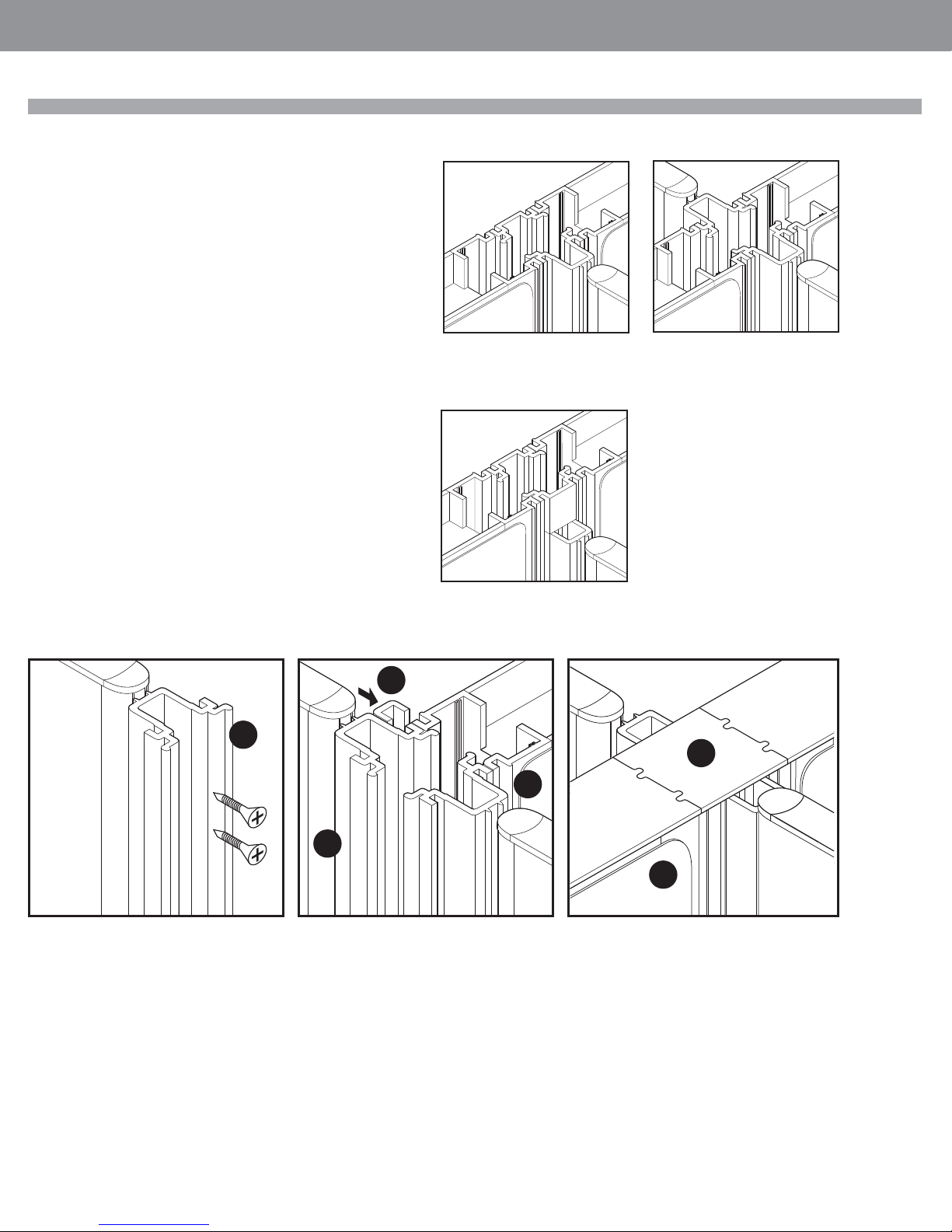
Off-Module Panel Connector
To connect two panels in an off-module, “T” confi guration remove panel vertical edge
trim and remove all connectors and spacers.
STEP 1: Secure top off-module bracket to panel vertical with supplied screws.
STEP 2: Drive levelers on the second panel all the way in and hold the panel in a tilted
position. Slide it carefully over the top bracket as illustrated, while making sure that the
bracket is seated inside of the top horizontal rail.
STEP 3: Bring the panel carefully into a vertical position and adjust its fi nal location.
STEP 4: Engage bottom off-module bracket in bottom horizontal panel rail.
STEP 5: Secure with supplied screws to panel vertical and level the whole assembly.
STEP 6: Install two set screws in the top bracket to prevent the top bracket from sliding
sideways and tighten carefully with supplied allan key. If the off-modularly connected
panel is higher then the perpendicular one, cut a vertical edge trim (removed earlier
from panel) and snap it onto the panel’s vertical, between top corner cap and top of the
upper, off-module bracket. If the perpendicular panel does not have base cable manager
installed, the bottom of the off-module panel will be exposed. In such instances cut 4
5/8” long pieces from the vertical edge trim and snap it onto the panel’s vertical at
the bottom.
• Summer 2017
Page • globalcontract.com4
GLOBALContract
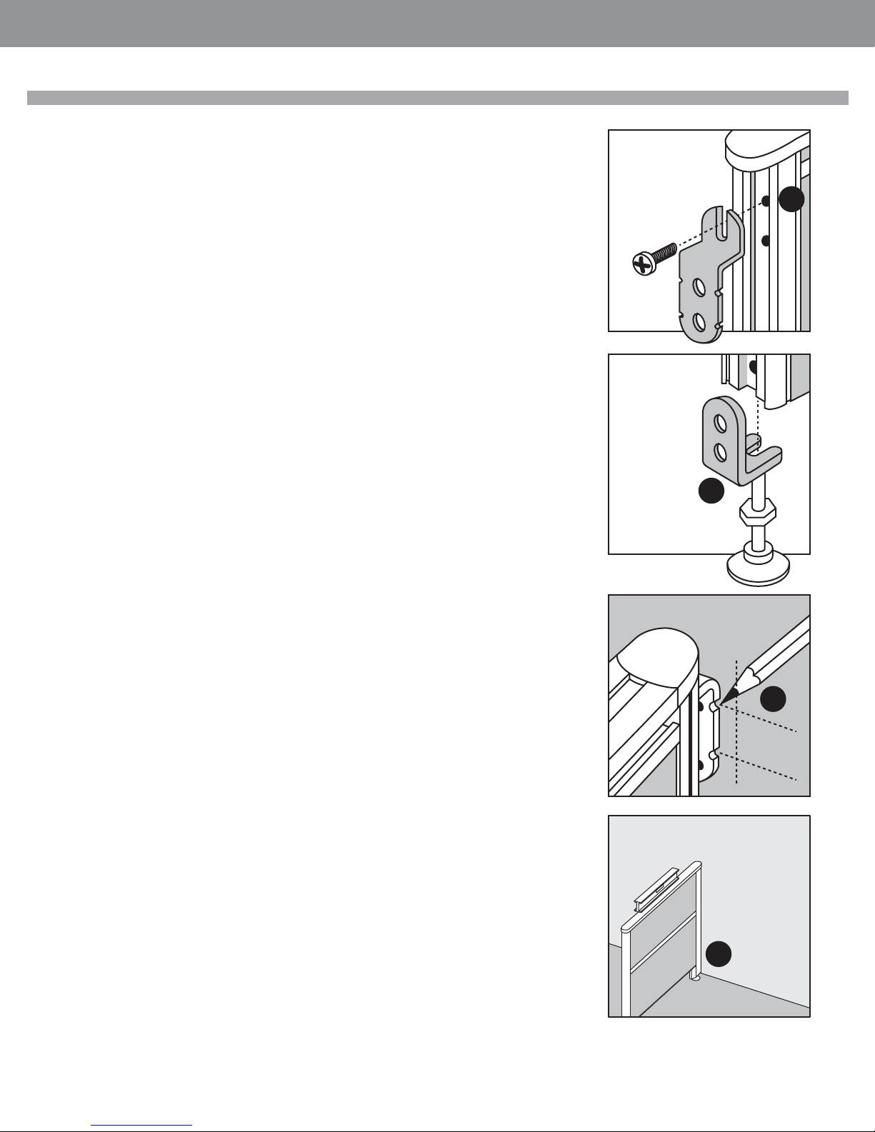
Wall Adapter
Remove panel vertical edge trim on the side facing the wall.
STEP 1: Secure temporarily top bracket to panel vertical member by driving supplied
screw into top hole.
STEP 2: Remove leveler, add supplied nut and lock the bottom bracket between the nut
and the bottom of panels vertical member.
STEP 3: Position levelled panel against the wall and mark the wall (both top and bottom
brackets have notches on either side to indicate anchor location). Use level to mark vertical line on the wall where centre of the panel is going to be, and install wall anchors, not
supplied. The choice of wall anchors depends on the construction and material of the
wall. ( ie. wood, steel, drywall etc..)
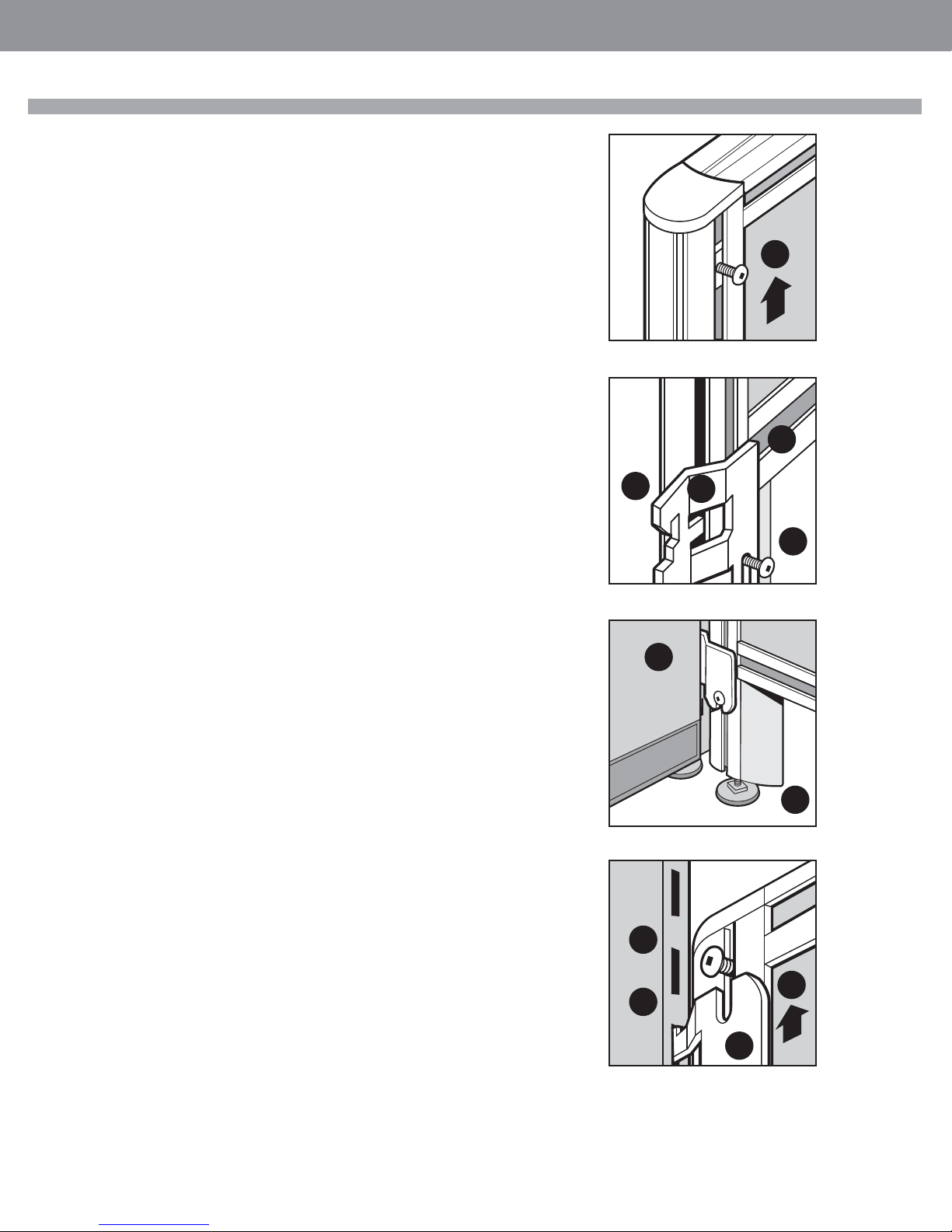
Loosen screw holding top bracket just enough to be able to slide the bracket down.
Drive the leveler with the nut out by 25 mm and slide the bottom bracket out.
Secure both brackets to the wall anchors.
STEP 4: Position panel with the screw over the top bracket while making sure that the
leveler is located within the bottom bracket. Adjust leveler while making sure that the top
bracket is seated behind the top screw head.
• Summer 2017
INSTALLATION GUIDELINES
1
STEP 5: As soon as the top screw is fi rmly seated in the top bracket level the panel (using leveler on the opposite side) and tighten the nut on the leveler to secure the bottom
bracket.
2
3
5
•Pageglobalcontract.com 5
GLOBALContract
INSTALLATION GUIDELINES
Diet to Boulevard Slot Connector
The kit consists of : 2 brackets
2 screw anchors
2 # 10-24x3/8” pan head machine screws
2 # 10 lock washers
Ensure that the complete BOULEVARD panel run is level before proceeding
with connecting perpendicular Diet panels.
• Summer 2017
STEP 1: Slide one screw anchor into panel’s vertical groove and secure it temporarily
below the panel’s top corner cap.
STEP 2: Install the bottom bracket with downward pointing hooks.
STEP 3: Align top of the bottom bracket with the top of the horizontal gap in panel’s bottom rail as illustrated. ensure that both bracket tabs (A) are engaged behind aluminum
lip if panel’s vertical frame member.
STEP 4: Slide one screw with screw anchor up into panel’s vertical groove, into bracket’s
slot and secure by tightening the screw.
STEP 5: Lift the Diet panel and hook it with the secured bottom bracket into slots on
perpendicular Boulevard panel.
STEP 6: Level Diet panel.
STEP 7: Align top bracket’s upward pointing hooks with slots in perpendicular Boulevard
panel while making sure that both bracket’s tabs (B) are engaged behind aluminum lip of
Diet panel’s vertical frame member.
STEP 8: Slide the bracket up until it’s hooks are fully engaged in Boulevard panel slots.
STEP 9: Secure the bracket by tightening the top screw.
1
3
2
A
4
5
Page • globalcontract.com6
6
9
8
7
B
GLOBALContract
Diet to Boulevard Slot Connector
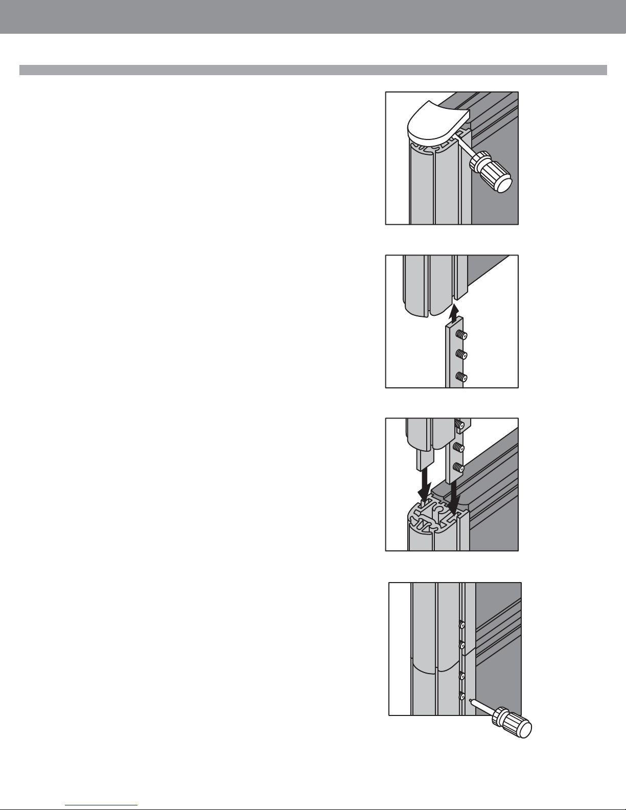
STEP 1: Remove panel’s top corner cap by carefully tapping the underside of the cap
through side vertical grooves.
STEP 2: Slide over panel connecting brackets halfway into over panel’s vertical groove
as illustrated.
Tighten only the top set screws in order to keep the brackets in place while leaving the
remaining set screws loose. (Ensure that the two lower set screws are not protruding
through the bracket as these would interfere with base panel’s vertical frame.
STEP 3: Slide the over panel with connecting brackets into the vertical grooves on the
base panel as illustrated.
STEP 4: Push the over panel down from the top while tightening remaining set screws
in all connecting brackets.
• Summer 2017
INSTALLATION GUIDELINES
•Pageglobalcontract.com 7
GLOBALContract
INSTALLATION GUIDELINES
Diet to Boulevard Connecting Kit
Diet - to - Boulevard connecting kit typically consists of two extruded aluminum
profi les. Boulevard strips, screws to secure connecting extruded profi le to Diet panel
and a cap.
There are three basic confi gurations (please note the position and the use of ‘Connector and Filler profi les):
STEP 1: Begin the actual installation by securing Connector profi le to Diet panel’s vertical with supplied screws. Note the asymmetrical shape of connector extrusion and
ensure that the larger side of the connector detail must be on the left side when facing
panel’s vertical extrusion or it would not engage with Boulevard panel interface.
STEP 2: Place Diet-Connector subassembly next to Boulevard panel. Ensure that
bottom of the Diet-BLVD Connector rests on top of self leveling feature at the bottom
of BLVD panels.
“T” (even height) “X” (even height
• Summer 2017
STEP 3: Install Boulevard capture strips.
STEP 4: Install Boulevard capture strips.
STEP 5: Install the next Boulevard panel or Aluminum vertical end trim.
STEP 6: Finish by installing top cap (injection molded cap for Boulevard 1 and 2;
aluminum cap for Boulevard System 3)
3
1
“T” (uneven height)
“X” uneven height requires one
more fi ller profi le
6
4
Page • globalcontract.com8
2
5
GLOBALContract
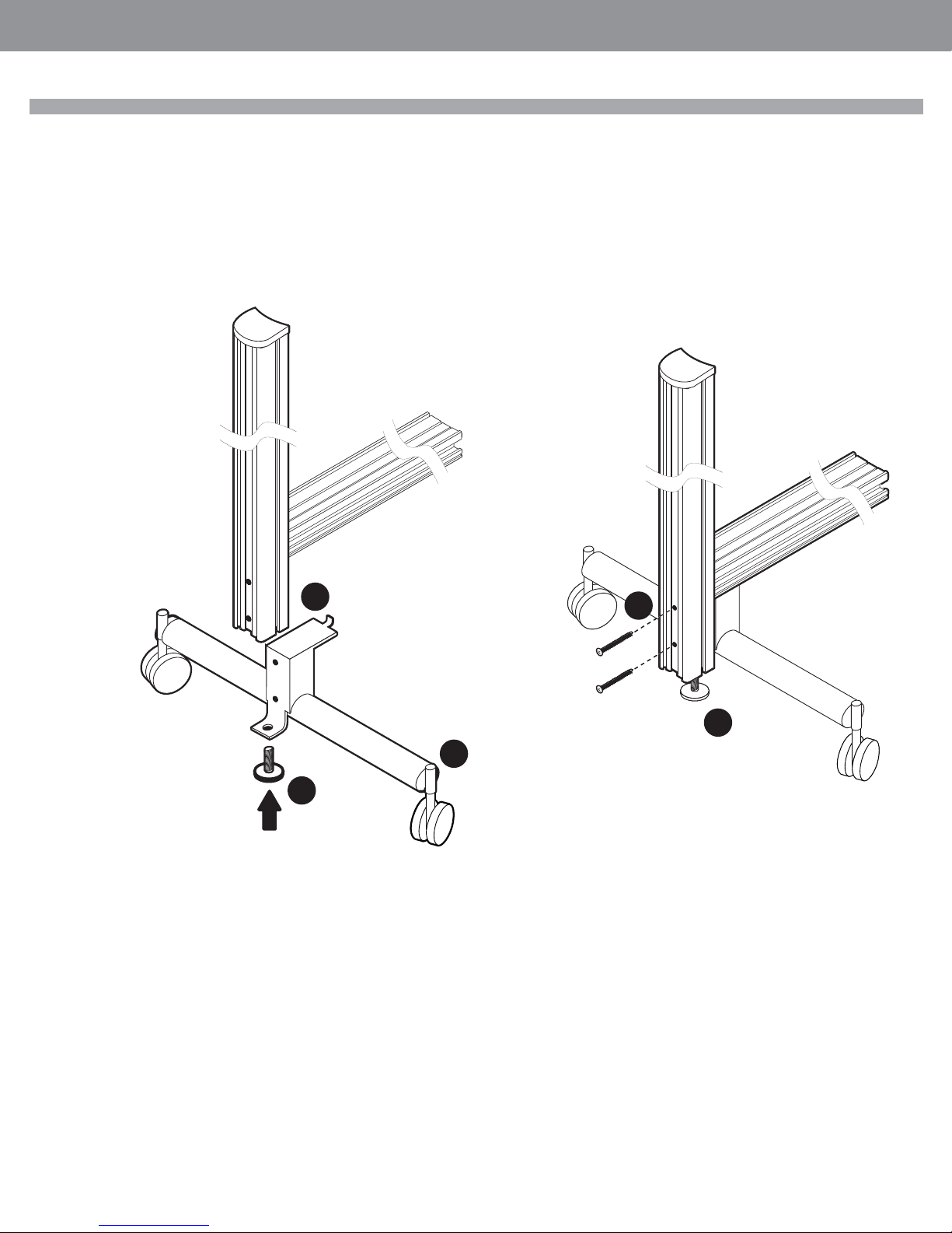
Diet Freestanding Panel Mobile Kit
STEP 1: Remove levelers from the bottom of the panel vertical extrusion.
STEP 2: Align the bracket so the legs with the casters run perpendicular to the length
of the panel.
STEP 3: Slide the bracket up until it fi ts into the horizontal bottom rail.
STEP 4: Remove the PVC cover and screw the bracket to the panel vertical through
the second bottom hole.
STEP 5: Re-attach the levelers.
• Summer 2017
INSTALLATION GUIDELINES
3
4
5
5
2
1
•Pageglobalcontract.com 9
GLOBALContract
INSTALLATION GUIDELINES
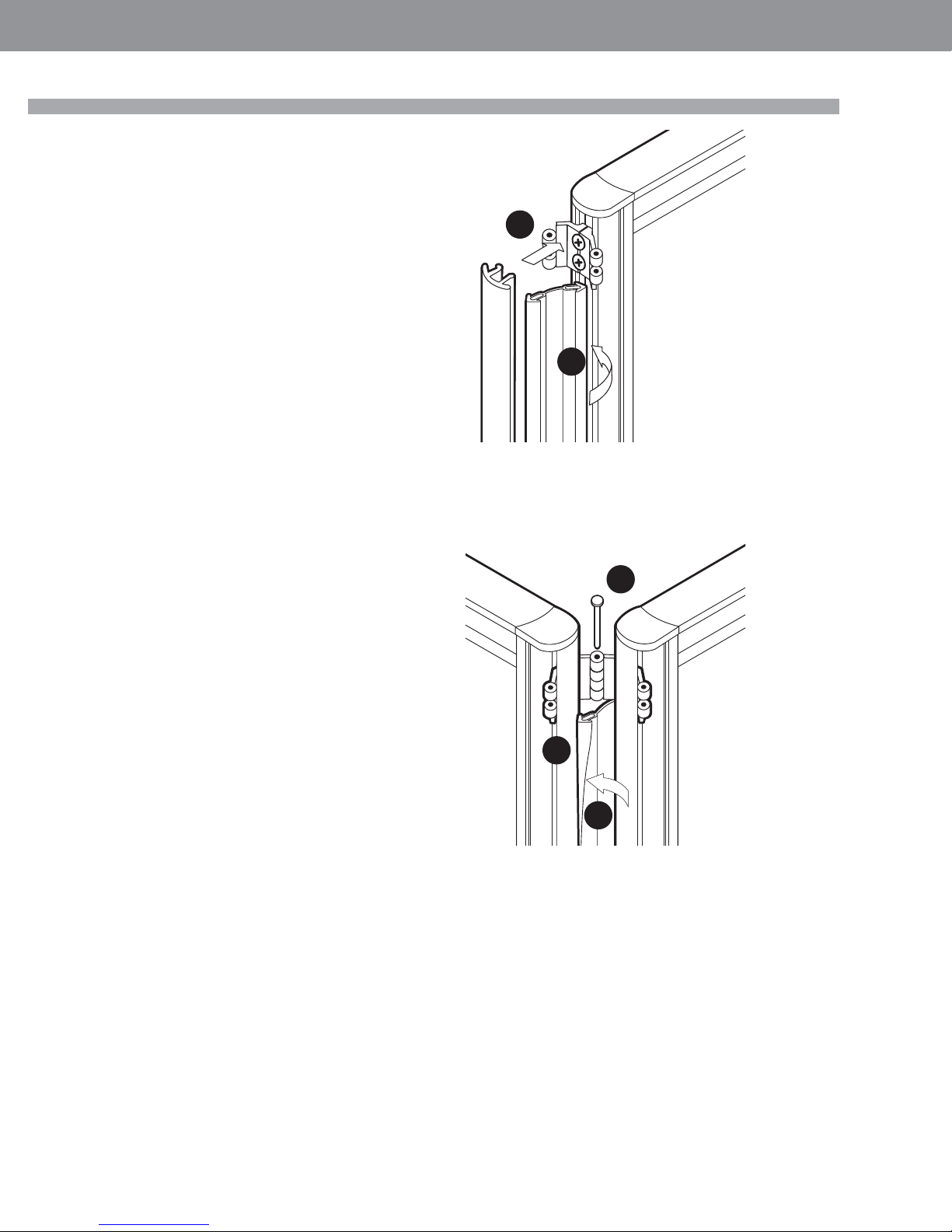
Diet Panel Gap Filler Installation
The Diet gap fi ller is installed into the groove between panel’s aluminum vertical frame
member and extruded PVC end trim. It is the same gap through which panel hinge
connectors protrude. The gap fi ller fi lls the gap between Diet panels, from the bottom
edge of the top hinge connector to the top edge of the bottom connector. If there are
more then two hinges connecting the two adjacent panels then trim the length of the
fi ller so that it fi lls the gaps between top and the middle hinge and, again, between the
middle hinge and the bottom hinge.
STEP 1: Hold the fi ller so that one arm of the ‘arrow’ is engaged behind the front edge
of panel’s aluminum vertical frame member.
STEP 2: Snap the extruded PVC end trim onto the panel’s vertical frame member while
ensuring that the second arm of the ‘arrow’ remains engaged behind the extruded
PVC trim.
• Summer 2017
2
STEP 3: Connect panels with connector pins.
STEP 4: Arrange the opposite end of the fi ller so that one ‘arrow’ is engaged along the
full height between the aluminum vertical frame member and extruded PVC end trim.
STEP 5: Proceed from top of the fi ller and tack the other ‘arrow’ behind the aluminum
frame member and the extruded PVC end trim.
1
3
4
Page • globalcontract.com10
5
 Loading...